
Monogram.
Use & Care Guide and
Installation Instructions
for ZDIB50
ZDIW50
Automatic Icemaker
General Electric Company
Louisville, KY40225
Monogram.":"
Automatic h:emaker
Pub. No. 49-6857
Parl No. 162D7745P002
] 2-95 C(;

Introduction
Your new Monogram icemaker makes an eloquent
statement of style, convenience and kitchen planning
flexibility. Whether you chose it for its purity of
design, practical features or assiduous attention to
detail--or for all of these reasons--you'll find that
your Monogram icemaker's superior blend of form
and function will delight you for years to come.
The Monogram icemaker was designed to provide
the flexibility to blend in with your kitchen cabinetry.
The information on the following pages will help
you operate and maintain your icemaker properly.
For a listing of dealers--or if you have other
questions--please call the GE Answer Center _:
(800.626.2000).
Contents
Appliance Registration ................. 3
Care and Cleaning .................. 7-10
Changing the Light Bulb ...... 10
Condenser .............................. 7
Filtering & Treating Water... 10
Icemaker System .................... 8
Inside Parts of the Icemaker...9
Outside Surfaces .................... 7
Consumer Services ..................... 20
Controls ........................................ 6
Features ......................................... 6
Installation Instructions ........ 16-18
Electrical Requirements ....... 16
Free Standing Installation .... 16
Grounding Instructions ........ 16
Model and Serial Number
Location ............................. 3, 6
Operating Instructions .............. 5, 6
Preparation ............................ 1l- 15
Changing the Bin
Door Panel ........................ 12
Changing the Lower
Access Panel ..................... 13
Leveling ............................... 11
Location ............................... 11
Custom Door
and Access Panels ............. 14
Thermostat Calibrations ....... 11
Unpacking the Icemaker ...... 11
Vacation and Moving ........... 15
Problem Solver ........................... 19
Safety Instructions ........................ 4
Warranty ..................................... 21
Questions?
Call GEAnswer Center
800.626.2000
2

HELP US HELP YOU...
Read this guide carefully.
It is intended to help you operate and maintain your
new icemaker properly.
Keep it handy for answers to your questions.
If you don't understand something or need
more help, call:
GE Answer Center _"_
800.626.2000
24 hours a day, 7 days a week
If you received a damaged icemaker...
Immediately contact the dealer (or builder) that sold
you the icemaker.
Save time and money.
Before you request service...
Check the Problem Solver. It lists minor operating
problems that you can correct yourself.
Write down the model and serial numbers.
You'll see them on a plate on the left side of the ice bin.
These numbers are also on the Consumer
Product Ownership Registration Card that came
with your icemaker.
Before sending in the registration card, please write
these numbers here:
Model Number
Serial Number
Use these model and serial numbers in any correspondence
or service calls concerning your icemaker.
IF YOU NEED SERVICE
To obtain service, see the Consumer Services page in
the back of this guide.
We're proud of our service and want you to be
pleased. If for some reason you are not happy with the
service you receive, here are three steps to follow for
further help.
FIRST, contact the people who serviced your
appliance. Explain why you are not pleased. In most
cases this will solve the problem.
NEXT, if you are still not pleased, write all the
details--including your phone number--to:
Manager, Consumer Relations
GE Appliances
Appliance Park
Louisville, KY 40225
FINALLY, if your problem is still not resolved, write:
Maior Appliance Consumer Action Program
20 North Wacker Drive
Chicago, IL 60606
3

IMPORTANT SAFETY INSTRUCTIONS
Read All Instructions Before Using This Appliance.
_ ARNING--To reduce the risk of fire,
electrical shock, or injury when using
your icemaker, follow basic precautions
including the following:
• Never allow children to operate, play with, or
crawl inside the icemaker.
• Never clean icemaker parts with flammable
fluids. The fumes can create a fire hazard or
explosion•
• For your safety: Do not store or use gasoline
or other flammable vapors and liquids in the
vicinity of this or any other appliance• The
fumes can create a fire hazard or explosion•
• Be sure your icemaker is properly installed and
grounded by a qualified technician in
accordance with the Installation Instructions•
• Do not attempt to repair or replace any part of
vour icemaker unless it is specifically
recommended in this guide• All other servicing
should be referred to a qualified technician•
• It is your responsibility to be sure your
lcemaker:
n has been installed where it is protected from
the elements.
-- is located so that the front is not blocked to
restrict incoming or discharge air flow.
-- is properly leveled.
is located in a well ventilated area with
temperatures above 55 °E (13°C.) and below
110°E (43°C.). Best results are obtained at
temperatures between 70°F. (21°C.) and
90°F. (32°C.).
is properly connected to a water supply
and drain.
is connected only to the proper kind of outlet,
with the correct electric supioly and grounding.
A 120 volt. 60 Hz.. 15 amp fused electrical
supply is required. NOTE: Time delay fuse or
circuit breaker is recommended.
is not used by anyone unable to operate
it properly.
-- is used only to do what icemakers are
designed to do.
-- is properly maintained.
SAVE THESE
INSTRUCTIONS

OPERATING YOUR ICEMAKER
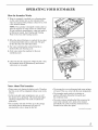
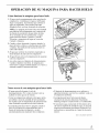
How the Icemaker Works
1. Water is constantly circulated over a freezing plate.
As the water freezes into ice, the minerals in the
water are reiected. This produces a sheet of ice with
a low mineral content.
NOTE: The icemaker is designed to make clear ice
from the maiority of water sources on a daily basis.
If your results are unsatisfactory, water may need to
be filtered or treated. See Filtering and Treating
Water in the Care and Cleaning section.
2. When the desired thickness is reached, the ice sheet
is released and slides onto a cutter grid. The grid
divides the sheet into individual cubes.
3. The water containing the reiected minerals is
drained after each freezing cycle.
4. Fresh water enters the machine for the next
icemaking cycle.
5. Cubes fall into the storage bin. When the bin is full,
the icemaker shuts off automatically and restarts
when more ice is needed.
_:'" J
Notes About This Icemaker
• Water enters only during the defrost cycle. Therefore
the first cycle will be completed without water in the
system.
• As the room and water temperatures vary, so will
the amount of ice produced. This means that higher
operating temperatures will result in reduced ice
production.
• The icemaker will shut off when ice in the storage
bin touches the bin thermostat well and will
automatically cycle to keep the bin full.
• The storage bin is not refrigerated and some meltage
will occur. This, too, varies with the room temperature.
• The icemaker needs good air circulation to
perform efficiently. Keep the front grille and
the condenser clean.
• The water system, including the filter screen in the
water inlet solenoid valve, needs to be cleaned
periodically for good circulation. Instructions are
located on the inner door panel.
(contimted next page)
5

OPERATING YOUR ICEMAKER
(continued)
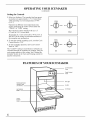
Setting the Controls
1. Select ice thickness. The icemaker has been preset
to produce ice approximately 1/2" (13 mm) thick,
while operating in a room temperature of 70°F.
(21°C.).
Operation in different room temperatures may
require readjusting the control toward either the
"THICK" or "TH1N" setting.
Best operation will be obtained with ice 1/2"
(13 mm) to 5/8" (16 mm) thick.
If operating in a warm room (above 90°F. [32°C.])
DO NOT set the control to maximum thickness or
the icemaker may malfunction.
2. To start the normal icemaking cycle, turn the Cycle
Control Knob to "ON."
3. To stop icemaker operation, turn Cycle Control
Knob to "OFF."
The "CLEAN" setting is used whenever solutions are
circulated through the icemaker for cleaning. Only the
water pump operates at this setting. See Cleaning the
Icemaker System in the Care and Cleaning section for
specific instructions.
THIN
NORMAL
THICK
ON
I
OFF -_- CLEAN
ICE CYCLE
NORMAL
\ I /
O
THIN - - THICK
ON
I
OFF - _ - CLEAN
ICE CYCLE
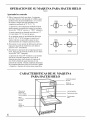
FEATURES OF YOUR ICEMAKER
Model and Serial
Number Plate
(not shown)
Ice Retainer
Baffle
Lower
Access
Panel
I II
III
Ice Thickness
Knob
Cycle Control
Knob
Bin Light
Ice Bin
Ice Scoop
6

CARE AND CLEANING
Periodically inspect and clean the icemaker to keep it
operating at peak efficiency and to prevent premature
failure of system components.
Both the icemaking system and the air-cooled
condenser need to be cleaned regularly.
The minerals reiected from the circulating water
during the freezing cycle will eventually form a hard
scaly deposit in the water system which prevents a
rapid release of the ice from the freezing plate.
Clean the ice and water system periodically to remove
mineral scale build-up. Frequency of cleaning
depends on water hardness. With hard water (15 to 20
grains/gal.), cleaning may be required as frequently as
every six months.
A dirty or clogged condenser:
• prevents proper air flow.
• reduces icemaking capacity.
• causes higher than recommended operating
temperatures which may lead to component failure.
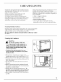
Cleaning Outside Surfaces
Wash the outside enamel surfaces and gaskets with warm water and mild
soap or detergent. Rinse and dry. Regular use of a good household
appliance cleaner and wax will help protect the finish.
Do not use abrasive cleaners on enamel surfaces as they may scratch
the finish.
Cleaning the Condenser
A _VARNING:
• Be sure the icemaker is OFF and
disconnected from the main power
supply. The icemaker could suddenly start if
not disconnected. Condenser fan rotation,
sharp condenser fins and hot tubing could
cause personal injury.
o Condenser fins can bend easily. Use care
when vacuuming the condenser to keep from
bending the fins.
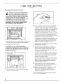
1. Disconnect the electrical power supply to the
icemaker and turn the Cycle Control Knob to "OFF."
2. Remove the screw from the top of the lower access
panel and the two screws from the grille area of the
lower access panel.
3. Pull forward at the bottom, then down to remove
the panel.
4. Remove dirt and lint from the condenser fins and
the icemaker compartment with a brush attachment
attached to a vacuum cleaner.
5. Replace the lower access panel and screws. The
top of the access panel needs to be secured under
the two metal tabs before replacing the screws.
6. Plug icemaker in and turn the Cycle Control Knob
to "ON."
Grill
Area
Screws
(continued next page)
7

CARE AND CLEANING
(continued)
Cleaning the Icemaker System
A WARNING: Most ice machine cleanersare citric or phosphoric acid which can
cause irritation even after dilution. In
case of contact with eyes, flush eyes thoroughly
with fresh water and contact a physician
immediately. In case of contact with skin, rinse
well with water. If swallowed, give large
amounts of water and contact a physician
immediately. Do not induce vomiting. KEEP
OUT OF REACH OF CHILDREN.
THI_- CLEAN
/
.
Turn the Cycle Control Knob to "OFF."
/Harness I.". I.I
"Screws (long) "_
2. Remove the two screws and slide the ice cutter grid
forward, out of the two slots near the water pan.
3. Unplug the electrical harness.
CAUTION:Any ice on the grid should be
melted under running warm water. Attempting
to pick the ice slab off the grid may stretch and
4. Remove all ice from the storage bin and the
freezing plate.
.
h, / JL
?sorews
, ,Water Pan I _:::r,_'"
.. Drain
Plug
Drain the water pan by removing the drain plug
and then replace the plug.
.
.
8.
Pour 1/2 gallon (1.9 L) of hot tap water into the
water pan* and turn the Cycle Control Knob to
"CLEAN." This warms up the system to make the
cleaning solution more effective. Let circulate for
five minutes. While tap water is circulating,
prepare the cleaning solution. Mix: 6 oz. (170 g)
powdered citric or phosphoric acid into 1/2 gallon
(1.9 L) hot water. (Citric and phosphoric acid
crystals are available or can be ordered from many
pharmacies or scientific supply houses.)
Commercial ice machine cleaners (liquid) are also
available from your dealer or refrigeration parts
supply stores. Mix according to instructions on
label (total quantity 1/2 gallon [1.9 L]).
Turn the Cycle Control Knob to "OFF" and drain
the water pan. (See step 5.)
Turn the Cycle Control Knob to "CLEAN"
and slowly pour the hot cleaning solution into
the water pan.* (If the solution foams while
pouring, wait until the foaming stops.) Then add
the balance of the solution.
.
Allow the solution to circulate until the scale has
dissolved (15 to 20 minutes). Severe scale build-
up may require repeated cleaning with a fresh
quantity of cleaning solution.
To clean scale off the side flanges of the freezing
plate, use rubber gloves and scrub with a non-
abrasive plastic scrubbing pad or nylon brush
dipped in cleaning solution.
Keep rubber gloves on to drain the cleaning
solution. Turn the Cycle Control Knob to "OFF"
and drain the water pan. (See step 5.)
10. Replace the plug and add 1/2 gallon (1.9 L) of
fresh water.* Set Cycle Control Knob on
"CLEAN," circulate five minutes and drain.
Repeat rinsing process.
*For easier pouring of water and cleaning solution,
use a 1- or 2-cup container.
8

Cleaning the Inside Parts of the Icemaker
WARNING:
• Do not operate the icemaker with the
lower access panel or control panel
removed. Electrical shock or personal injury
could result.
o Do not wash plastic parts in dishwasher.
They cannot withstand temperatures above
145°E (63°C.).
.
Turn the Cycle Control Knob to "OFF" and
disconnect the electrical power supply to the
machine. Open the storage bin door and remove
any ice that is in the bin.
.
3.
Remove the ice retainer baffle by flexing it and
then slide it off the studs.
Remove the ice cutter grid by unscrewing the two
screws, sliding the grid forward and unplugging
the electrical wire harness.
.
Remove the water pan by unscrewing and
removing the two screws and washers.
Water L__
Pump J/
_Hose
Water Distlributor
.
Remove the water distributor from the freezing
plate. It is held in place by rubber end caps.
Remove the inlet hose and clean all water
distributor holes and the small orifice in the inlet
side of the distributor. When replacing the
distributor, make sure the end caps are located in
the evaporator flange detents and that the water
distributor holes face down.
.
.
9.
Wash the interior components (ice retainer baffle,
cutter grid, water pan, inlet hose and water
distributor) and the storage bin, door gasket and
ice scoop with mild soap or detergent and warm
water. Rinse in clean water. These components
should also be cleaned in a solution of 1 oz.
(29.6 ml) of chlorine bleach in 1 gallon (3.8 L)
warm water. Rinse again thoroughly in clean water.
Replace the interior components: water
distributor, inlet hose and water pan.
Check the following:
• The hose from the water valve is in the water pan.
• The rubber drain plug is in the water pan.
• The water distributor is seated and the holes are
facing down.
• The hose is reconnected to the pump and the
water distributor.
• The hose from the water pan is inserted into the
storage bin drain opening.
10. Reconnect the electrical harness, slide the cutter
grid into place and tighten the screws. Replace
the ice retainer baffle.
11. Turn Cycle Control Knob to "ON."
(continued next page)
5. Remove the hose from the water pump. 9

CARE AND CLEANING
(continued)
Filtering and Treating Water
In most areas it will be beneficial to filter or treat the
water being supplied to the icemaker. It can improve
the reliability of the icemaker, reduce water system
maintenance and produce the best quality of ice.
The installation of apolyphosphate feeder will
generally reduce scale build-up and the icemaker will
require less frequent cleaning.
Municipal water systems are generally treated with
chlorine to maintain a safe drinkable water supply.
Activated carbon filters will sufficiently remove the
residual chlorine from the water to reduce surface
staining of stainless steel materials in the icemaker.
For more information on filtering and treating the
water, see the dealer from whom you purchased
your icemaker.
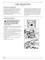
Changing the Light Bulb
A WARNING: Before removing the lightbulb, either unplug the icemaker or
disconnect the electricity leading to
the icemaker at the main power supply.
Shock and injury can occur if electricity
remains connected.
The icemaker has a light bulb in the top of the storage
bin. To replace it, open the bin door and follow these
instructions:
1. Disconnect the icemaker from the power supply.
2. Remove the two screws and slide the ice cutter grid
forward, out of the two slots near the water pan. Set
the ice cutter grid on the bin door.
3. Press the front of the light shield in while pulling
down to remove it from the light bracket.
4. Remove the bulb. Replace it with a 15-watt bayonet
base type bulb.
5. Replace the light shield, ice cutter grid and two
screws.
6. Reconnect the power supply.
/
Light
Switch
€ \
Screws
Shield
10

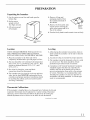
PREPARATION
Unpacking the Icemaker
1. Lay the carton on rear face and break open the
bottom flap.
2. Set the carton
upright with all
four flaps outward.
3. Lift carton up and
off icemaker.
"2
/
/
ttom
Flaps
.
°
Remove all tape and
packaging material from
the outside and inside of
the cabinet.
Remove the front grille; take
out the screws securing the
grille at the bottom and lift it
free of the cabinet.
Remove
Interior
Packing
6. Turn the fan by hand to make certain it moves freely.
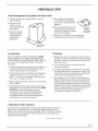
Location
THIS ICEMAKER MUST BE INSTALLED IN AN
AREA PROTECTED FROM THE ELEMENTS,
SUCH AS WIND, RAIN, WATER SPRAY OR DRIP.
1. Place the icemaker so the front side will be
completely unobstructed to provide proper air flow.
2. The area should be well ventilated with temperature
above 55°F. (13°C.) and below ll0°F. (43°C.). Best
results are obtained between 70°F. (21 °C.) and
90°F. (32°C.).
3. Provision for electricity, water and drain
connections should be determined.
4. The icemaker may be closed in on the top and three
sides, but the front MUST BE unobstructed for air
circulation and proper operation. Installation should
be such that the cabinet can be moved forward for
servicing, if necessary.
Leveling
1. After placing the icemaker into position, check to
make certain the icemaker is level side to side and
front to back.
°
3.
°
Accurate leveling is essential for proper operation.
The icemaker should be shimmed so that it is solid
as well as level. The shims should be of hard
permanent type material such as masonite.
Compliance with National Sanitation Foundation
standards requires that this type of product be
sealed to the floor at the bottom rail in order to
prevent contamination from spills or the entrance
of vermin. Therefore, we recommend that when
installing the icemaker you seal it to the floor in
accordance with those standards. A silicone-type
sealer is recommended.
Thermostat Calibrations
If the icemaker is installed above two thousand feet of altitude, the bin and
evaporator thermostats must be adjusted to a warmer setting. Disconnect
electricity, remove thermostat and follow the directions for turning the
altitude adjustment screw as shown in the label on each thermostat.
(continued next page)
11

PREPARATION
(continued)
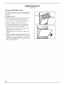
Changing the Bin Door Panel
You can easily change the color of the front panel on
the storage bin door. Two colors are available: black
and white.
To change the panel:
1. Open the storage bin door. Remove the two screws
on the top of the door which hold the handle.
2. Loosen the screws in both of the side trim pieces.
3. Remove the handle and the handle insert.
4. Carefully slide the panel out. You will find the
reverse side is black. For units with black panels
showing, the reverse side will be white.
5. Choose the color you want to show and carefully
slide the panel back into the door.
NOTE: Be careful not to scratch the panel as it is
inserted.
6. Replace the handle insert and tighten the screws in
both side trim pieces. Replace the handle and screws.
NOTE: You can make a decorative wood front to
match existing cabinets. See the section on Custom
Door and Access Panels.
Handle
Insert
1
12

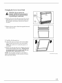
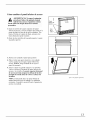
Changing the Lower Access Panel
control panel removed. Electrical shock
1. Remove the screw from the top of the lower access
panel and the two screws in the bottom grille area.
Pull forward at the bottom, then down to remove
the panel.
Grill
Area
Screws
2. Remove the two screws from the top panel trim and
remove the top trim.
/
3. Carefully slide the panel out.
4. Choose the color you want to show and carefully
slide the panel back into the lower access panel.
NOTE: Be careful not to scratch the panel as it
is inserted.
5. Replace the top trim and screws. Replace the lower
access panel assembly and screws. The top of the
access panel needs to be secured under the two
metal tabs before replacing the screws.
NOTE: You can make a decorative wood front to
match existing cabinets. See the section on Custom
Door and Access Panels.
(continued next page)
13

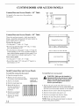
CUSTOM DOOR AND ACCESS PANELS
Custom Door and Access Panels--I/4" Thick
Cut panels to the same size as the production
metal panel.
Door
Bin
11//4"
Lower
Panel
t
11W_o"
Wood Panel
Dimensions
17"
Custom Door and Access Panels--3/4" Thick
These door and access panels--both raised and flat
design--should be constructed in the same manner as
typical cabinet doors or drawers.
Storage bin door panel:
• Cut the panel 17" wide x 111/4"high.
• Rout the top and both sides 5/16" wide, 1/2" deep
for a total thickness of 1/4".
• Rout the bottom of the panel 1" wide, 1/2" deep for
a total thickness of 1/4". This will allow the door to
open without binding against the lower panel. For a
custom appearance, consider tapering this 1" rout.
Lower access panel:
• Cut the panel 17" wide x 1115/I61"high.
• Rout all four sides 5/16" wide and 1/2" deep for a
total thickness of 1/4".
91 17"
II,
-f
Storage Bin Door Panel 11//4"
Rout 1/2" deep, 1" wide across bottom
Rout 1/2" deep, 5/16" wide top and sides
Rout 1/2" deep, 5/16" wide on all sides
__
Lower Access Panel 5/_0"
,_ 17" Im,
3/4" Thick Panels
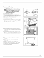
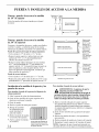
Install Custom Door and Access Panels
To install the storage bin door panel:
1. Open the storage bin door.
2. Remove the two screws on top
of the door which hold the handle.
3. Remove the handle.
4. Slide the metal panel out.
5. Break off the ribs on
the door insulation to
allow for the wood
thickness.
6. Slide the wood panel
into the door frame.
7. Replace the handle
and screws.
Remove all door
insulation ribs to
accept wood
panel thickness
14
To install the lower access panel:
WARNING: Make sure the icemaker is
_ disconnected from the main powe r supply
before removing the lower access panel.
Failure to do so could result in electric
1. Remove the screw at the top of the lower access
panel assembly and the two screws at the bottom that
hold the lower access panel assembly to the icemaker.
2. Remove the two screws from the top panel trim.
3. Slide the metal panels and spacers out.
4. Slide the wood panel into the door frame.
5. Replace the top of the panel assembly.
NOTE: Make sure the galvanized panel is replaced
in back of the panel assembly.

Vacation and Moving
"WARNING: Make sure the icemaker is
disconnected from the main power supply
before removing the lower access panel.
Failure to do so could result in electric
shock or personal injury.
To shut down the icemaker:
1. Disconnect the electrical power supply to the
icemaker and turn the Cycle Control Knob to "OFF."
2. Remove all ice from the storage bin.
3. Shut off the water supply.
4. Remove the screw from the top of the lower access
panel and the two screws from the grille area of the
lower access panel, then remove the panel. Pull
forward at the bottom, then down.
NORMAL
\ I /
0
THIN - - THICK
ICE
OFF - "_
CYCLE
Lower
Access
Panel
Grille
Area --
Screws
5. Disconnect the inlet and outlet lines to the water
valve. Allow these lines to drain and then reconnect
to the valve.
6. Replace the lower access panel and screws. The
top of the access panel needs to be secured under
the two metal tabs before replacing the screws.
Inlet
I
L.
7. Remove water from the drain lines and drain
water pan.
8. Before using again, clean the icemaker and
storage bin.
NOTE: All components of the icemaker are
permanently lubricated at the factory. They should
not require any additional oiling throughout the
normal life of the machine.
Water
Pan
15

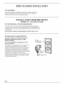
FREE STANDING INSTALLATION
For the Installer
When this icemaker is installed free standing (not under a counter) we
strongly recommend that the bottom rear comers of the icemaker be
fastened to the floor to prevent accidental tipping.
INSTALLATION REQUIREMENTS
IMPORTANT...Please Read Carefully
For the Electrician--Electrical Requirements
A 115 Volt, 60 Hz, AC only, 15 Amp fused electrical supply is required
(time delay fuse or circuit breaker is recommended). It is recommended that
a separate circuit, serving only this appliance, be provided. DO NOT use an
extension cord.
ELECTRICAL GROUND IS REQUIRED ON THIS APPLIANCE.
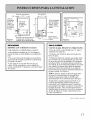
Recommended Grounding Methods
DO NOT, UNDER ANY CIRCUMSTANCES,
REMOVE THE POWER SUPPLY CORD
GROUND PRONG.
For your personal safety, this appliance must be
properly grounded.
This appliance is equipped with a power supply cord
having a 3-prong grounding plug. To minimize
possible shock hazard, the cord must be plugged into
a mating 3-prong grounding type wall receptacle,
grounded in accordance with the National Electrical
Code and local codes and ordinances. If a mating wall
receptacle is not available, it is the personal
responsibility and obligation of the customer to have a
properly grounded 3-prong wall receptacle installed
by a qualified electrician.
3-Prong
Grounding Type
Wall Receptacle
3-Prong
Grounding
Plug
Power Supply
Cord
16

Right end view
3/4" -'_ _ 237/8"
t 1
Water inlet
1/4" O.D. solenoid valve
water line. /
compression \ /
fitting at \ ,,/_ _ ,
water valve _ ._'--------..... r'_?"
_L _" 1,1.'
_, , _J 33/Z' '-_1
/'/2" -i'-. ..... L [.
,,
Bend field supplied water line to
Figure 1 connect to water valve fitting
l
34W="
2V2" -_'_"
4" tong 5/8" I.D.
rubber drain
tube--run to
open drain
[_NJr d --11/4" Min.
["_/4- "_ -- Hole for field
3/4" _ supplied water line
\k
-- /' i
_ ,%,_-
.2,T
_ / 0o-
34I/2" 9" TF_ i
.,
/ 1 41/2"t0 \
y__ center line \
/, 18"-----4
Figure 2
UTILITIES
OBSERVE LOCAL CODES
Each installation is unique but will require:
• A cold water inlet of 1/4" O.D. soft copper
tubing and a shutoff valve.
• Either a gravity drain system or a sump pump
to lift the water to an existing drain.
• An electrical branch circuit of 115 volt, 60 Hz.
1 phase, with a 15 amp delayed action fuse or
circuit breaker.
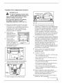
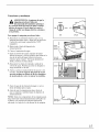
FORTHEPLUMBER
Connect to water. (Observe local codes.)
• Use 1/4" O.D. soft copper tubing for the cold
water supply.
• Provide a convenient manual shutoff valve in the
water line.
• Position the tubing so it can enter the access
hole located in the right-hand rear of the
icemaker cabinet. The tubing should extend
beyond the cabinet front so when the icemaker
is pushed back in position it will reach the water
inlet location in the front. See Figure 1.
NOTE: Always purge the water line before
making the final connection to the inlet of the
water valve to prevent possible water valve
malfunction.
With the icemaker in its permanent location,
bend the tubing to meet the connection at
the water valve. The garden hose threaded
compression fitting is found in the parts bag.
This joint provides a convenient disconnect
for service. Be sure the tubing is clear of
compressor, to prevent rattle.
LEVELING
• After placing the icemaker into position, check
to make certain the icemaker is level side to side
and front to back.
• Accurate leveling is essential for proper
operation.
• The icemaker should be shimmed so that it is
solid as well as level. The shims should be of
hard permanent type material such as masonite.
• Compliance with National Sanitation
Foundation standards requires that this type of
product be sealed to the floor at the bottom rail
in order to prevent contamination from spills or
the entrance of vermin. Therefore, we
recommend that when installing the icemaker
you seal it to the floor in accordance with those
standards. A silicone-type sealer is recommended.
ALTERNATEMETHOD
If a drain connection directly below the
drain tube outlet is not available, install a
UL-listed drain pump in the rear compartment
of the icemaker.
Drain pump specifications:
• UL-listed and have a UL-listed, 120VAC, 3-wire
grounded service cord
• Overall outside dimensions (maximum):
15" wide x 6" deep x 91/2"high
• Pump flow rate (minimum): 24.0 gph (0.4 gpm)
@ 12 feet lift
• Operating temperature range 55°E to 110°E
(13°C. to 43°C.)
(continued next page)
17

DRAIN PUMP
• When the drain connection is below the level of
the icemaker, a drain pump may be used to lift the
water to an available drain. Use only an approved
drain pump kit ZDK50 from your dealer.
• Complete installation instructions are included
with the drain pump kit.
CHECKOPERATION
• Start the icemaker by turning the service
switch to "ON" and opening the line water valve.
• NOTE: Left is "OFF"--Middle is "ON"--Right
is "CLEAN." In "CLEAN" position, only the
pump operates.
• Check the condenser fan to make sure it is
revolving.
• Water will not enter the pump pan until the
freezing plate gets cold and the icemaker goes
into a harvest cycle.
• Check for even water flow over the freezing
plate. The icemaker must be level for proper
operation.
• Check for desired cube thickness and after 24
hours adjust ifnecessary. Maximum ice yield will
be obtained with ice thickness at 1/2" to 5/8".
• Replace the grille.
18

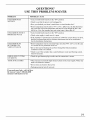
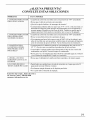
QUESTIONS?
USE THIS PROBLEM SOLVER
PROBLEM
ICEMAKER DOES
NOT RIfN
ICEMAKER RUNS BUT
PRODUCES NO ICE
ICEMAKER RUNS
BUT PRODUCES
VERY LITTLE ICE
GRID IS NOT CUTTING
ICE SHEETS
TASTE 1N ICE CUBES
POSSIBLE CAUSE
• Cycle Control Knob must be in the "ON" position.
• Check to see that the power cord is plugged in.
• Have you checked your home's main fuses or circuit breaker box?
• Room temperature must be above 55°F. (13°C.). Otherwise, the bin thermostat
may sense the cold room temperature and shut off even though the bin is not
full of ice. Also. the icemaker may not restart once it does shut off.
• Cycle Control Knob must be in the "ON" position.
• Check water supply to make sure it is open.
• If the icemaker is operated at an elevation of 2,000 feet or more above sea level,
both the bin thermostat and ice thickness thermostat need to be recalibrated.
See the Installation Instructions.
• Room temperature may be extremely high, more that 90°F. (32°C.). In this case
it is normal for ice production to be low.
• Dirt or lint may be blocking the air flow through the finned condenser.
Condenser needs to be cleaned.
• Check to see if the icemaker has a scale build-up in water and freezing system.
Clean if necessary.
• Check the grid harness plug to make sure the connection is secure.
• There may be an unusually high mineral content in the water supply. Water may
need to be filtered or treated.
• Do not store any foods in the ice bin.
• Packaging material not all removed.
If you need more help...call, toll free:
GE Answer Center <"_,800.626.2000
consumer information service
19

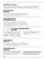
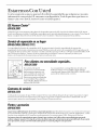
We'll Be There
With the purchase of your new GE appliance, receive the assurance that if you ever need
information or assistance from GE, we'll be there. All you have to do iscall-toll-free!
GEAnswerCenter®
800.626.2000
®
Whatever your question about any GE major appliance, GE Answer Center
information setsTice is m_ailable to help. Your call-and your question- will be
answered promptly and courteously. And you can call any time. GE Answer
Center ®sets_ice is open 24 hours a day, 7 days a week.
In-HomeRepairService
800-GE-CARES(80&432-2737)
AGE consumer sms_ice professional will provide expert repair sets,ice,
scheduled at a time that's convenient for you. Many GE Consumer Sets,ice
company-operated locations of*er you sets,ice today or tomorrow, or at your
convenience (7:00 a.ln. to 7:00 p.m. weekdays, 9:00 a.m. to 2:00 p.m. Saturdays).
Our f)tctoxy-trained technicians know your appliance inside and out-so most
repairs can be handled in just one visit.
_o
I
SECTIONA-A
ForCustomersWithSpecialNeeds...
800.626.2000
Upon request, GE will provide
Braille controls for a variety, of
GE appliances, and a brochure to
assist in planning a barrier4i'ee
kitchen for persons with limited
lnobility. To obtain these items,
fl'ee of charge, call 800.626.2000.
Consumers with impaired hearing or speech who have
access to a TDD or a conventional teletype_Titer may
call 800-TDD-GEAC (800-833-4322) to request
information or sets_ice.
ServiceContracts
800-626-2224
You can have the secure feeling that GE Consumer Sets,ice will still be there
after your warranty, expires. Purchase a GE contract while your warranty, is still
in effect and you'll receive a substantial discount. With a lnultiple-year contract,
you're assured of flmlre sets,ice at todw's prices.
PartsandAccessories
800-626-2002
Individuals qualified to service their own appliances can
have parts or accessories sent directly to their home. The
GE parts system provides access to over 47,000 parts...and
all GE Genuine Renewal Parts are flflly warranted. VISA,
MasterCard and Discover cards are accepted.
User maintenance instructions contained in this booklet
cover procedures intended to be performed by any user.
Other servicing generally should be referred to qualified
service personnel. Caution must be exercised, since
improper servicing may cause unsafe operation.
20
Page is loading ...
Page is loading ...
Page is loading ...
Page is loading ...
Page is loading ...
Page is loading ...
Page is loading ...
Page is loading ...
Page is loading ...
Page is loading ...
Page is loading ...
Page is loading ...
Page is loading ...
Page is loading ...
Page is loading ...
Page is loading ...
Page is loading ...
Page is loading ...
Page is loading ...
Page is loading ...
Page is loading ...
Page is loading ...
Page is loading ...
Page is loading ...
-
 1
1
-
 2
2
-
 3
3
-
 4
4
-
 5
5
-
 6
6
-
 7
7
-
 8
8
-
 9
9
-
 10
10
-
 11
11
-
 12
12
-
 13
13
-
 14
14
-
 15
15
-
 16
16
-
 17
17
-
 18
18
-
 19
19
-
 20
20
-
 21
21
-
 22
22
-
 23
23
-
 24
24
-
 25
25
-
 26
26
-
 27
27
-
 28
28
-
 29
29
-
 30
30
-
 31
31
-
 32
32
-
 33
33
-
 34
34
-
 35
35
-
 36
36
-
 37
37
-
 38
38
-
 39
39
-
 40
40
-
 41
41
-
 42
42
-
 43
43
-
 44
44


Sharp R-341Z Owner's manual
- Category
- Ovens
- Type
- Owner's manual
Ask a question and I''ll find the answer in the document
Finding information in a document is now easier with AI