Page is loading ...
31-481
Lijadora de Tambor Doble de 26 in.
Ponceuse à double tambour de 66 cm
Operating Instructions and Parts Manual
Manuel d’utilisation
Manual de instrucciones
Français (18)
Español (34)
INSTRUCTIVO DE OPERACIÓN, CENTROS
DE SERVICIO Y PÓLIZA DE GARANTÍA.
LÉASE ESTE INSTRUCTIVO
ANTES DE USAR EL PRODUCTO.
www.DeltaMachinery.com
26 IN. Dual Drum SaNDer

2
TABLE OF CONTENTS
IMPORTANT SAFETY INSTRUCTIONS ...................................2
SAFETY GUIDELINES - DEFINITIONS .................................... 3
GENERAL SAFETY RULES ...................................................... 3
POWER CONNECTIONS .......................................................... 5
MOTOR SPECIFICATIONS ....................................................... 5
GROUNDING INSTRUCTIONS ................................................ 5
EXTENSION CORDS ................................................................ 6
FEATURES AND COMPONENTS ............................................. 6
FUNCTIONAL DESCRIPTION .................................................. 7
PRODUCT SPECIFICATIONS ................................................... 7
UNPACKING .............................................................................. 7
ASSEMBLY ................................................................................ 8
Securing Switch to Frame ................................................... 8
Table Elevation Crank Handle .............................................8
Dust Collect ......................................................................... 8
ADJUSTMENTS ......................................................................... 9
Replacing the Sanding Belt ................................................. 9
Feed Belt Tracking ............................................................... 9
Drive Belt Tension ..............................................................10
Replacing Feed belt .......................................................... 11
Parallelism of Sanding Drums ........................................... 12
Roller Pressure .................................................................. 12
Drum Height ...................................................................... 13
OPERATION ............................................................................. 13
OPERATING TIPS .................................................................... 13
Depth of Wood Removal ................................................... 13
Sanding Imperfect Stock................................................... 13
Stock Feeding Angle ......................................................... 14
Multi-Piece Sanding .......................................................... 14
Face Frames and Raised Panel Doors ............................. 14
Edge Sanding .................................................................... 14
SELECTING ABRASIVES ........................................................ 14
MAINTENANCE PROCEDURES ............................................ 15
Routine Inspection.............................................................15
Lubrication ......................................................................... 15
Cleaning the Sanding Belts ............................................... 15
TROUBLESHOOTING ............................................................. 15
ACCESSORIES ........................................................................ 16
WARRANTY .............................................................................16
FRANÇAIS ................................................................................ 18
ESPAÑOL ................................................................................. 34
IMPORTANT SAFETY INSTRUCTIONS
READ AND UNDERSTAND ALL WARNINGS AND OPERATING INSTRUCTIONS BEFORE USING THIS
EQUIPMENT. Failure to follow all instructions listed below, may result in electric shock, fire, and/or
serious personal injury or property damage.
Woodworking can be dangerous if safe and proper operating procedures are not followed. As with all
machinery, there are certain hazards involved with the operation of the product. Using the machine with
respect and caution will considerably lessen the possibility of personal injury. However, if normal safety
precautions are overlooked or ignored, personal injury to the operator may result. Safety equipment such
as guards, push sticks, hold-downs, featherboards, goggles, dust masks and hearing protection can reduce your
potential for injury. But even the best guard won’t make up for poor judgment, carelessness or inattention. Always
use common sense and exercise caution in the workshop. If a procedure feels dangerous, don’t try it. Figure out
an alternative procedure that feels safer. REMEMBER: Your personal safety is your responsibility. For additional
information please visit our website www.DeltaMachinery.com.
This machine was designed for certain applications only. DELTA
®
Power Equipment Corporation
strongly recommends that this machine not be modified and/or used for any application other than
that for which it was designed. If you have any questions relative to a particular application, DO NOT use the
machine until you have first contacted DELTA
®
to determine if it can or should be performed on the product.
If you have any questions relative to its application DO NOT use the product until you have written DELTA
®
Power
Equipment Corporation and we have advised you. Contact us online at www.DeltaMachinery.com or by mail at
Technical Service Manager, DELTA
®
Power Equipment Corporation, 4825 Highway 45 North, Jackson, TN 38305.
Information regarding the safe and proper operation of this tool is available from the following sources:
• Power Tool Institute, 1300 Sumner Avenue, Cleveland, OH 44115-2851or online at www.powertoolinstitute.com
• National Safety Council, 1121 Spring Lake Drive, Itasca, IL 60143-3201
• American National Standards Institute, 25 West 43rd Street, 4 floor, New York, NY 10036 www.ansi.org - ANSI 01.1
Safety Requirements for Woodworking Machines
• U.S. Department of Labor regulations www.osha.gov

3
SAFETY GUIDELINES - DEFINITIONS
This manual contains information that is important for you to know and understand. This information relates to
protecting YOUR SAFETY and PREVENTING EQUIPMENT PROBLEMS. To help you recognize this information, we
use the symbols below. Please read the manual and pay attention to these sections.
Indicates an imminently hazardous situation which, if not avoided, will result in death or serious
injury.
Indicates a potentially hazardous situation which, if not avoided, could result in death or serious
injury.
Indicates a potentially hazardous situation which, if not avoided, may result in minor or moderate
injury.
Used without the safety alert symbol indicates potentially hazardous situation which, if not avoided,
may result in property damage.
GENERAL SAFETY RULES
WARNING FAILURE TO FOLLOW THESE RULES MAY RESULT IN SERIOUS PERSONAL INJURY.
•
FOR YOUR OWN SAFETY, READ AND UNDERSTAND THE INSTRUCTION MANUAL BEFORE OPERATING THE
UNIT.
Learn the unit’s application and limitations as well as the specific hazards peculiar to it.
•
KEEP WORK AREA CLEAN.
Cluttered areas and benches invite accidents.
•
DON’T USE IN DANGEROUS ENVIRONMENT.
Don’t use this unit in damp or wet locations, or expose it to rain.
Keep work area well-lighted.
•
KEEP CHILDREN AND VISITORS AWAY.
All children and visitors should be kept a safe distance from work area.
•
DISCONNECT UNIT
before servicing.
•
CHECK DAMAGED PARTS.
Before further use of the unit, properly repair or replace any part that is damaged.
1. Read and understand the warnings posted on the
machine and in this manual. Failure to comply with
all of these warnings may cause serious injury.
2. Replace the warning labels if they become
obscured or removed.
3. This Dual Drum Sander is designed and intended
for use by properly trained and experienced
personnel only. If you are not familiar with the
proper and safe operation of a drum sander, do not
use until proper training and knowledge have been
obtained.
4. Do not use this machine for other than its intended
use. If used for other purposes, Delta Power
Equipment Company, Inc. disclaims any real or
implied warranty and holds itself harmless from any
injury that may result from that use.
5. Always wear approved safety glasses/face shields
while using this Dual Drum Sander.
6. Before operating this drum sander, remove tie,
rings, watches and other jewelry, and roll sleeves
up past the elbows. Remove all loose clothing and
confine long hair. Non-slip footwear or anti-skid
floor strips are recommended. Do not wear gloves.
7. Wear ear protectors (plugs or muffs) during
extended periods of operation.
FAILURE TO FOLLOW THESE RULES MAY RESULT IN SERIOUS INJURY.
8. Some dust created by power sanding, sawing,
grinding, drilling and other construction activities
contain chemicals known to cause cancer,
birth defects or other reproductive harm. Some
examples of these chemicals are:
• Lead from lead based paint.
• Crystalline silica from bricks, cement and other
masonry products.
• Arsenic and chromium from chemically treated
lumber.
Your risk of exposure varies, depending on how often
you do this type of work. To reduce your exposure to
these chemicals, work in a well-ventilated area and
work with approved safety equipment, such as face or
dust masks that are specifically designed to filter out
microscopic particles.
1. Do not operate this machine while tired or under
the influence of drugs, alcohol or any medication.
2. Make certain the switch is in the OFF position
before connecting the machine to the power
source.
3. Make certain the machine is properly grounded.
4. Make all machine adjustments or maintenance with
the machine unplugged from the power source.
continued on page 4

4
5. Form a habit of checking to see that all extra
equipment such as adjusting keys, wrenches,
scrap, stock, and cleaning rags are removed away
from the machine before turning on.
6. Keep safety guards in place at all times when the
machine is in use. If removed for maintenance
purposes, use extreme caution and replace the
guards immediately when maintenance is complete.
7. Make sure the drum sander is firmly secured to the
floor before use.
8. Check damaged parts. Before further use of the
machine, a guard or other part that is damaged
should be carefully checked to determine that it will
operate properly and perform its intended function.
Check for alignment of moving parts, binding of
moving parts, breakage of parts, mounting and
any other conditions that may affect its operation.
A guard or other part that is damaged should be
properly repaired or replaced.
9. Provide for adequate space surrounding work area
and non-glare, overhead lighting.
10. Keep the floor around the machine clean and free of
scrap material, oil and grease.
11. Keep visitors a safe distance from the work area.
Keep children away.
12. Make your workshop child proof with padlocks,
master switches or by removing starter keys.
13. Give your work undivided attention. Looking
around, carrying on a conversation and “horse-
play” are careless acts that can result in serious
injury.
14. Maintain a balanced stance at all times so that you
do not fall or lean against the sanding belt or other
moving parts. Do not overreach or use excessive
force to perform any machine operation.
15. Use the right tool at the correct speed and feed
rate. Do not force a tool or attachment to do a job
for which it was not designed. The right tool will do
the job better and safer.
16. Use recommended accessories; improper
accessories may be hazardous.
17. Maintain machinery with care. Follow instructions
for lubricating and changing accessories.
18. Turn off the machine before cleaning. Use a brush
or compressed air to remove dust or debris — do
not use your hands.
19. Do not stand on the machine. Serious injury could
occur if the machine tips over.
20. Never leave the machine running unattended. Turn
the power off and do not leave the machine until it
comes to a complete stop.
21. At all times hold the stock firmly.
22. Do not use this sander for other than it intended
use. If used for other purposes, Delta Power
Equipment Company Inc., disclaims any real or
implied warranty and holds itself harmless for any
injury or damage which may result from that use.
SAVE THESE INSTRUCTIONS.
Refer to them often and use them to instruct others.
5
FIG. A FIG. B
A separate electrical circuit should be used for your machines. This circuit should not be less than #12 wire and
should be protected with a 20 Amp time lag fuse. If an extension cord is used, use only 3-wire extension cords
which have 3-prong grounding type plugs and matching receptacle which will accept the machine’s plug. Before
connecting the machine to the power line, make sure the switch (s) is in the “OFF” position and be sure that the
electric current is of the same characteristics as indicated on the machine. All line connections should make good
contact. Running on low voltage will damage the machine.
DO NOT EXPOSE THE MACHINE TO RAIN OR OPERATE THE MACHINE IN DAMP LOCATIONS.
Your machine is wired for 230 volts, 60 HZ alternating current. Before connecting the machine to the power source,
make sure the switch is in the “OFF” position.
THIS MACHINE MUST BE GROUNDED WHILE IN USE TO PROTECT THE OPERATOR FROM
ELECTRIC SHOCK.
1. All grounded, cord-connected machines:
In the event of a malfunction or breakdown, grounding provides a path of least resistance for electric current to
reduce the risk of electric shock. This machine is equipped with an electric cord having an equipment-grounding
conductor and a grounding plug. The plug must be plugged into a matching outlet that is properly installed and
grounded in accordance with all local codes and ordinances.
Do not modify the plug provided - if it will not fit the outlet, have the proper outlet installed by a qualified electrician.
Improper connection of the equipment-grounding conductor can result in risk of electric shock. The conductor with
insulation having an outer surface that is green with or without yellow stripes is the equipment-grounding conductor.
If repair or replacement of the electric cord or plug is necessary, do not connect the equipment-grounding conductor
to a live terminal.
Check with a qualified electrician or service personnel if the grounding instructions are not completely understood,
or if in doubt as to whether the machine is properly grounded.
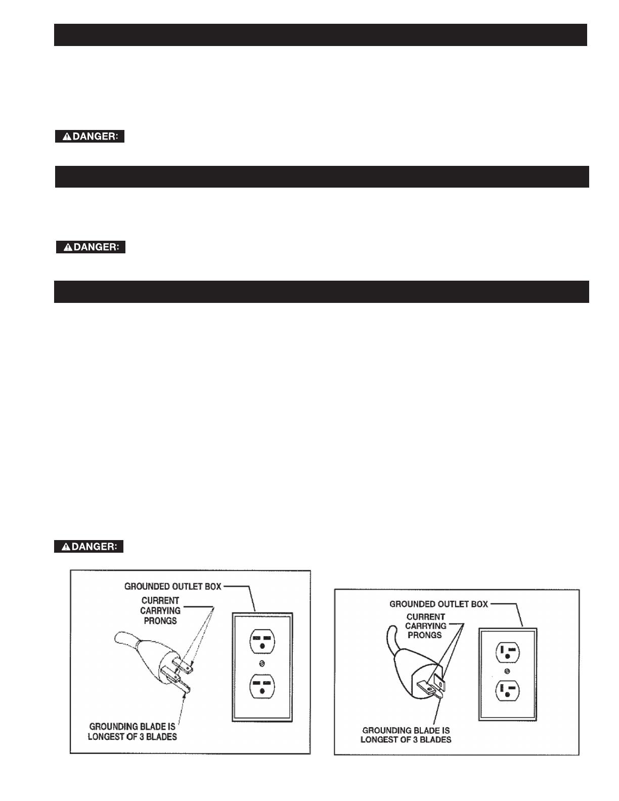
Use only 3-wire extension cords that have 3-prong grounding type plugs and matching 3-conductor receptacles that
accept the machine’s plug, as shown in Fig. A.
Repair or replace damaged or worn cord immediately.
IN ALL CASES, MAKE CERTAIN THE RECEPTACLE IN QUESTION IS PROPERLY GROUNDED.
IF YOU ARE NOT SURE, HAVE A QUALIFIED ELECTRICIAN CHECK THE RECEPTACLE.
POWER CONNECTIONS
MOTOR SPECIFICATIONS
GROUNDING INSTRUCTIONS

6
KEY FEATURES AND COMPONENTS
EXTENSION CORDS
Use proper extension cords. Make
sure your extension cord is in good
condition and is a 3-wire extension cord which has a
3-prong grounding type plug and matching
receptacle which will accept the machine’s plug.
When using an extension cord, be sure to use one
heavy enough to carry the current of the machine.
An undersized cord will cause a drop in line voltage,
resulting in loss of power and overheating. The table
on the right shows the correct gauge to use
depending on the cord length. If in doubt, use the
next heavier gauge. The smaller the gauge number,
the heavier the cord.
MINIMUM GAUGE EXTENSION CORD
RECOMMENDED SIZES FOR USE WITH STATIONARY ELECTRIC MACHINES
Ampere
Rating
Volts Total Length
of Cord in
Feet
Gauge of Extension
Cord
0-6
0-6
0-6
0-6
120
120
120
120
up to 25
25-50
50-100
100-150
18 AWG
16 AWG
16 AWG
14 AWG
6-10
6-10
6-10
6-10
120
120
120
120
up to 25
25-50
50-100
100-150
18 AWG
16 AWG
14 AWG
12 AWG
10-12
10-12
10-12
10-12
120
120
120
120
up to 25
25-50
50-100
100-150
16 AWG
16 AWG
14 AWG
12 AWG
12-16
12-16
12-16
120
120
120
up to 25
25-50
14 AWG
12 AWG
GREATER THAN 50 FEET NOT RECOMMENDED
FIG. C
FIG. 1
1. Variable speed feed belt
2. 3HP continuous duty motor
3. Dual 26” drums
4. Sanding elevation cursor
5. Elevation crank handle
6. Switch assembly
7
PRODUCT SPECIFICATIONS
FUNCTIONAL DESCRIPTION
Model 31-481 DELTA
®
26” Dual Drum Sander is specifically designed to handle both rough and final sanding
processes in a single pass. This machine features an adjustable height automatic feed table and comes with 80-grit
and 120-grit pre-cut sanding belts already installed. This dual drum sander is powered by a 3HP continuous duty
sealed motor with a variable speed feed that enables you work at 3-20 S.F.P.M. The wide feed belt accepts stock as
big as 25 ½” and allows you to sand pieces up to 12 ¼” thick.
UNPACKING
The machine is heavy, be careful when removing it from the shipping container! Failure to comply
may cause serious injury and/or damage to the sander and/or property!
Your DELTA
®
Dual Drum Sander comes packed in a single container. Use a safety strap to avoid tip over when lifting
machine. Check shipping carton and machine for damage before unpacking.
Open the shipping container. Carefully remove packaging materials, parts and machine from shipping carton.
Always check for and remove protective shipping materials around motors and moving parts. Lay out all parts on a
clean work surface and check that all parts are present and in good condition:
DESCRIPTION (QUANTITY)
Delta 26” Dual Drum Sander (1)
12mm Open End Wrench (1)
Elevation Handle (1)
5mm Hex Wrench (1)
6mm T-Handle Wrench (1)
2mm T-Handle Wrench (1)
Elevation Bracket (1)
DRUM MOTOR SPECIFICATIONS
Type Induction Ball bearing/
Continuous Duty
Horsepower 3HP
Amps 16A
Voltage 230V
Phase Single
Hertz 60Hz
RPM 3,450
BELT FEED MOTOR SPECIFICATIONS
Type Universal
Horsepower 1/6
PRODUCT SPECIFICATIONS
Maximum sanding width 25-1/2”
Maximum board thickness 12-1/4”
Minimum board thickness ¼”
Minimum board length 6”
Feed Speed 3-20 FPM (variable)
Compare the items to inventory figures; verify that all items are accounted
for before discarding the shipping box. Report any missing or damaged
parts to your distributor or dealer. Prior to tool assembly and use, read
this manual thoroughly to familiarize yourself with proper assembly,
maintenance and safety procedures.
Remove any protective materials and coatings from all of the parts and the
drum sander. The protective coatings can be removed by spraying WD-40
on them and wiping it off with a soft cloth. This may need to be redone
several times before all of the protective coatings are removed completely.
If any parts are missing, do not attempt to plug in the power
cord and turn “ON” the machine. The machine should
only be turned “ON” after all the parts have been obtained and installed
correctly.
Number of Sanding Drums 2
Drum Size 5” x 26”
Drum Speed 1,550 RPM
Dust Ports 2-4”
PRODUCT DIMENSIONS
Footprint 17-3/4” x 43”
Length 31”
Width 46”
Height 53”
Weight 485 lbs.
SHIPPING DIMENSIONS
Carton Type Wooden Crate
Length 33”
Width 48”
Height 55”
Gross Weight 535 lbs.
8
FIG. 2
ASSEMBLY
TOOLS REQUIRED
• Flat head screw driver
• 10mm open-end wrench
FIG. 3
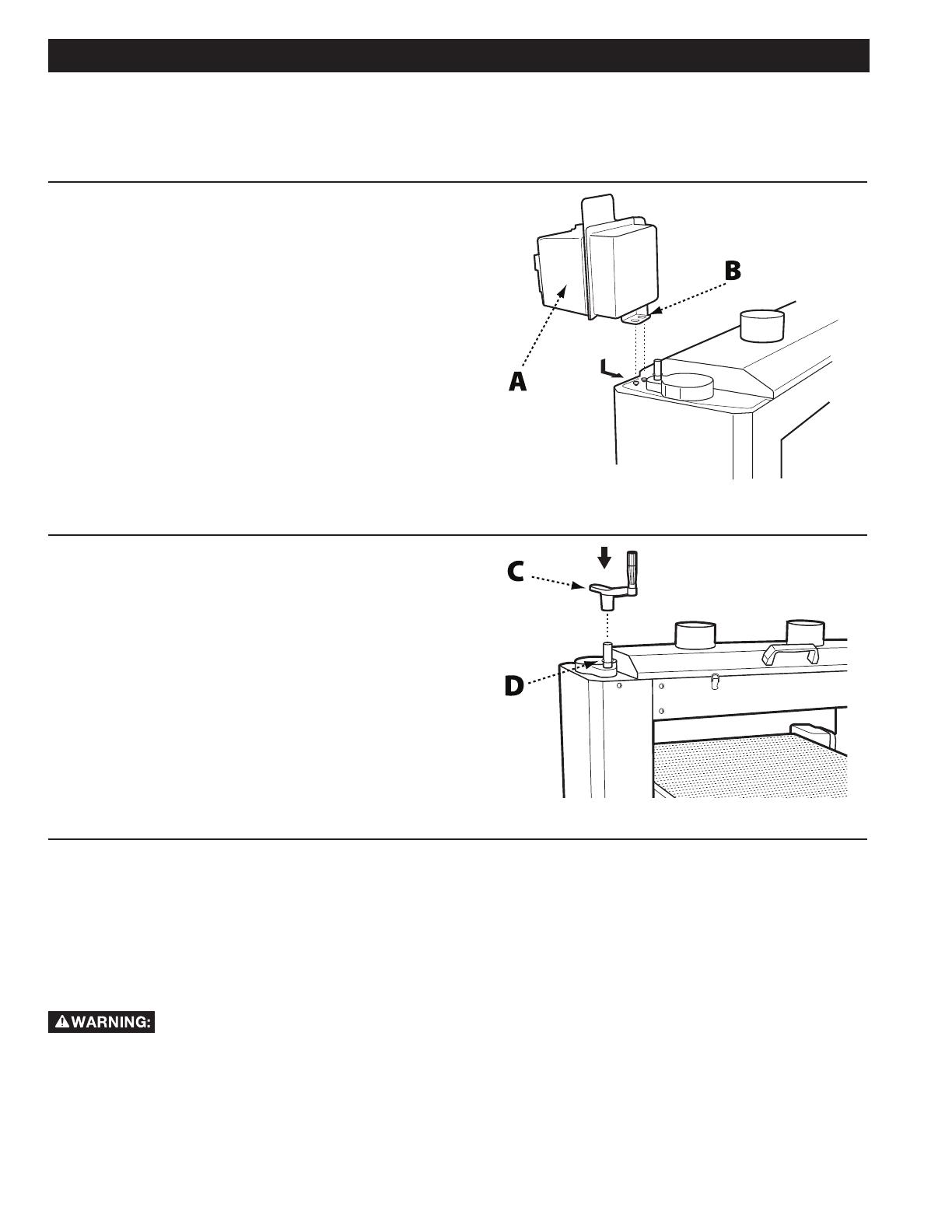
SECURE SWITCH BOX TO FRAME
Tools Required: 10mm open-end wrench
Parts: None
Hardware Needed: Two 10mm hex head screws
1. Locate the two threaded holes on the upper right side of
the machine as shown in Fig. 2.
2. Attach the two 10mm hex head screws to the mounting
plate, leaving about 1/8” between the screw head and
mounting plate.
3. Mount switch assembly (A) to the machine frame by
aligning the keyholes (B) in the switch assembly over the
screw heads and pushing the assembly back and into
position.
4. Tighten screws using 10mm open-end wrench.
ASSEMBLE TABLE ELEVATION
CRANK AND HANDLE
Tools Required: None
Parts: Table Elevation Crank
Table Elevation Handle
Hardware Needed: None
1. Install the table elevation crank (C) by aligning the
groove in the bottom of the crank with the pin located on
the shaft (D). See Fig. 3.
2. Screw the table elevation handle into the threaded hole
in the table elevation crank.
CONNECT DUST COLLECTOR TO DUST COLLECTION PORT
Tools Required: Flat head screwdriver
Parts: None
Hardware Needed: Two 4” Ring Clamps (not provided)
Your DELTA
®
Dual Drum Sander is equipped with two 4-inch dust collection ports. These must be connected to dust
collector hoses to ensure safe operation.
Do not attempt to operate this tool without first connecting it to an adequate dust collection system.
1. Fit a 4” ring clamp over the end of each dust collection hose.
2. Place a dust collection hose over each dust collection port and tighten ring clamp with the flat head screwdriver.

9
ADJUSTMENTS
FIG. 4
FIG. 5
TO REPLACE THE SANDING
BELT
1. Lift the upper guard up and tilt it toward the rear of
the machine to expose the drums.
2. Locate the spring-loaded locking clamp (A) on the
right end of the drum. Squeeze the clamp open
and remove the end of the sanding belt (B) from the
drum slot. See Fig. 4.
3. Slowly pull the old sanding belt off the drum.
4. Squeeze the spring-loaded locking clamp on the left
end of the drum and remove the old sanding belt.
5. Squeeze the spring-loaded locking clamp on the
left end of the drum and insert the end of the new
sanding belt approximately 2 inches into the drum
slot.
6. Release the clamp to lock the belt end in place.
7. Rolling the roller by hand, carefully wind the
sanding belt around the drum, making sure to keep
it snug. The edges of the belt should meet without
overlapping.
NOTE: The Dual Drum Sander is designed to achieve coarse and fine sanding in a single pass. Therefore, the
coarser sanding belt should always be installed on the front roller with the finer belt on the rear roller.
8. Squeeze the locking clamp on the right end of the
drum and insert as much of the end of the sanding
belt into the slot as possible.
9. Release the clamp to lock the belt in place.
10. Roll the roller by hand to ensure the belt is snug
and the edges meet without overlapping.
TO ADJUST THE FEED BELT
TRACKING
For proper stock feed, both sides of the feed belt must
travel at exactly the same rate. If the feed belt tracks to
the right or left during operation, you will need to adjust
the tension.
NOTE: If the belt tracks to the left, tighten the left
tensioning bolt. If it tracks to the right, tighten the right
tensioning bolt.
1. Locate the feed belt tensioning bolts as shown in
Fig. 5.
2. Turn the sander on and, depending on which
direction the feed belt is tracking, use a 6mm Allen
wrench to tighten either the left or right adjustment
bolt in 1/4-turn increments until the feed belt tracks
evenly.

10
ADJUSTMENTS
FIG. 6
TO ADJUST DRIVE BELT
TENSION
1. Remove the elevation cursor by unscrewing the
retaining screw.
2. Remove the eight Phillips head bolts and washers
securing the left and right side guards (A) to the
machine and remove the guards. See Fig. 6.
3. Use a 6mm Allen wrench to remove the four hex
cap bolts and washers securing the bottom guard
(B) to the machine. See Fig. 7.
4. Raise the telescoping panels (C) high enough to
expose the motor mount (D). See Fig. 7. Prop up
using a scrap block of wood.
5. Locate the two M12 nuts (E) that raise and lower the
motor. See Fig. 7.
6. To increase tension on the drive belts, loosen the
bottom nuts then tighten the top nuts.
7. Drop the telescoping panels back into place and
re-secure to the bottom guard.
8. Re-attach the side guards and elevation cursor.
FIG. 7
11
FIG. 9
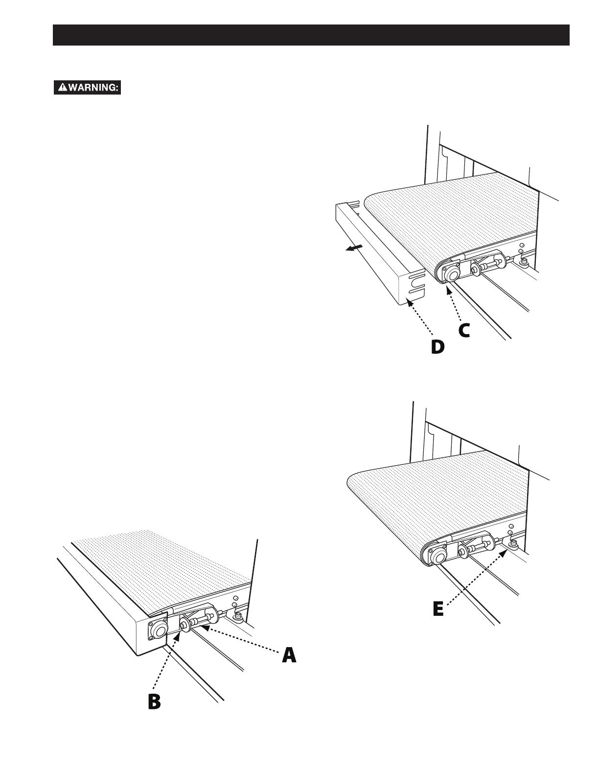
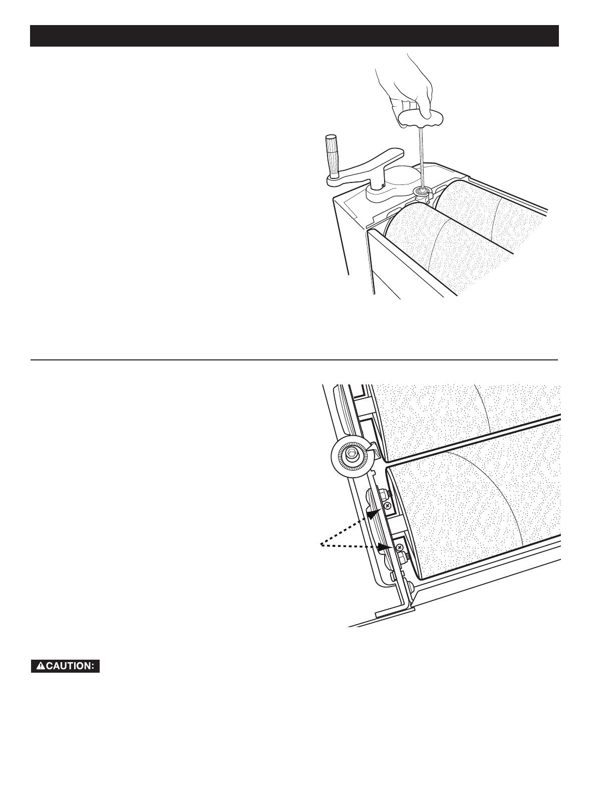
TO REPLACE THE FEED BELT
This step requires two adults. The feed table is heavy, be careful when disconnecting and
removing it from the machine. Failure to comply may cause serious injury and/or damage to the
sander and/or property!
ADJUSTMENTS
1. Using the table elevation crank and handle, lower
the table as far as it will go.
2. Release tension on the feed belt by backing off
the locking nuts (A) on the feed belt adjustment
bolts (Fig. 8) and then tightening the feed belt
adjustment bolts (B) until they are loose enough to
remove the feed belt assembly.
3. Loosen but do not remove the eight Philips head
screws (C) holding the bearings to either side of the
front of the feed table. See Fig. 9.
4. Remove the front guard (D) by sliding it forward.
5. Locate and remove the four 6mm hex head screws
(E) securing the feed table to the base. See Fig. 10.
6. With the aid of a second adult, carefully remove the
feed table through the rear of the machine being
careful to angle it away from the motor housing.
7. Position the feed table on its side and remove the
worn feed belt.
8. Carefully slide the new feed belt into place.
9. Slide feed belt assembly back onto machine base
through the rear, being careful not to damage motor
housing.
10. Replace and tighten the four 6mm hex cap head
screws to secure the feed table to the machine
base.
11. Replace the front guard and retighten the Phillips
head screws on each bearing.
12. Re-tension the feed belt.
13. Adjust the tracking as described on page 9.
FIG. 10
FIG. 8
12
ADJUSTMENTS
FIG.12
TO ADJUST PARALLELISM OF
SANDING DRUMS
The front sanding drum has been factory adjusted and
needs no further adjustment. The rear sanding drum
must be adjusted for parallelism.
1. Lift the upper guard up and tilt it toward the rear of
the machine to expose the sanding drums.
2. Using the 6mm wrench provided, rotate the cap
screws, indicated in Fig. 11, on either end of the
rear drum.
3. Turning the cap screws clockwise will raise the
drum while turning it counterclockwise will lower
the drum.
4. Repeat this dial setting on the opposite end of the
drum.
5. Replace the upper guard to its original position over
the drums.
NOTE: For proper operation of the machine, the dial
settings at both ends of the drum must be identical.
FIG. 11
TO ADJUST ROLLER PRESSURE
The pressure rollers maintain tension upon the
workpiece as it passes through the machine. If the
stock refuses to pass through the machine, or the
finished surface is uneven, the tension on the pressure
rollers may need adjusting.
1. Lift the upper guard up and tilt it toward the rear of
the machine to expose the sanding drums.
2. Locate the roller pressure adjustment screws as
indicated in Fig. 12.
3. Using a Phillips head screw driver, turn the screws
clockwise to increase the roller pressure on the
workpiece; or counterclockwise to decrease the
pressure.
4. Adjust both sides of the pressure rollers to ensure
parallelism with the drums.
5. Replace the upper guard to its original position over
the drums.
Do not overtighten the adjustment screw. Too much roller pressure will prevent the workpiece from
passing through the machine, and may cause the feed belt to stop.

13
Front Grit / Rear Grit Setting (mm)
80/100, 120/150, 120/180, 150/220 .15
80/120, 100/150, 100/180 .30
60/100, 36/38 .40
36/120 .56
36/60 .76
36/80 .9
ADJUSTMENTS
TO ADJUST DRUM HEIGHT
In order to accommodate different abrasive grits on
the drums, the height of the drums from the workpiece
must vary. The height of the front drum has been
factory set and should not be adjusted. The back drum
is designed for easy adjustment.
1. Lift the upper guard up and tilt it toward the rear of
the machine to expose the sanding drums.
2. Locate the drum height adjustment screw as shown
in Fig. 13.
3. Rotate the adjustment screw to the desired
measurement.
4. Repeat this same adjustment at the opposite end of
the roller to maintain parallel orientation to the front
drum.
5. Replace the upper guard to its original position over
the drums.
NOTE: For proper operation of the machine, the dial
settings at both ends of the drum must be identical.
IMPORTANT: The chart at the right shows the proper
settings based upon sanding grits.
FIG. 13
OPERATION
The basic operating procedure for the Dual Drum Sander is as follows:
1. Establish the depth of wood removal and set table height.
2. Start drums.
3. Start feed belt and select proper feed rate.
4. Ensure dust collection system is running.
5. Feed stock through machine.
OPERATING TIPS
DETERMINING DEPTH OF
WOOD REMOVAL
Given the variables of grit abrasion, wood type, and
feed rate, determining proper depth of removal may
take some experimentation. For best results, use
scrap wood to practice sanding and to develop skill
and familiarity with the machine before doing finish
work. Also consider any cups and/or crowns in the
workpiece.
A good rule of thumb when sanding with grits finer than
80 is to lower the drum so it contacts the workpiece
but drum can still be rotated by hand. For grits coarser
than 80, lower the drum slightly more.
SANDING IMPERFECT STOCK
When sanding stock with a cup or crown, place the
crown up. This will stabilize the stock to help prevent
tipping or rocking during sanding. After the crown has
been removed and the top is flat, turn the stock over
and sand the opposite side. To avoid personal injury,
take special care when sanding stock that is twisted,
bowed, or otherwise varies in thickness from end to
end.
If possible, support such stock as it is being sanded
to keep it from slipping or tipping. Use an extra roller
stand, help from another person, or hand pressure on
the stock to minimize potentially hazardous situations.

14
OPERATING TIPS
STOCK FEEDING ANGLE
Some pieces, because of their dimensions, will need
to be fed into the machine at a 90-degree angle
(perpendicular to the drums). However, even a slight
offset angle of the stock will provide for more effective
stock removal. The optimum feeding angle is about
60-degrees. Angling the workpiece for stock removal
provides other advantages, such as less loading of
certain areas of the drums due to glue lines or mineral
streaks in the stock, more even wear of abrasive strips,
potentially faster feed rates, and lighter loads on the
motor. For the best final finish, however, the stock
should be fed with the grain on the final one or two
passes.
MULTIPLE-PIECE SANDING
When sanding multiple pieces simultaneously, make
sure to stagger (step) the pieces across the width of
the feed belt. Multiple pieces should also be of similar
thickness and this helps to ensure consistent contact
with the pressure rollers.
SANDING FACE FRAMES AND
RAISED PANEL DOORS
It is important to have the proper abrasive contact
when doing this type of sanding. If the machine is set
to take an excessive depth of cut, the result can be a
gouge or dip as the drum goes from sanding the rails
at full width to sanding just a few inches of width of the
stiles.
EDGE SANDING
When edge sanding, the sander will mimic the opposite
edge of the stock which is lying on the feed belt.
Because of this, it is important for the stock edge to
have been ripped at the proper angle to the face before
the sanding process. When edge sanding small stock,
clamp several pieces together to prevent them from
slipping on the feed belt.
The abrasive material you choose will have a
substantial effect on the performance of your sander.
Variations in paper type, weight, coating and durability
all contribute to achieving your desired finish.
As with any sanding operation, first begin sanding
with a coarser grit, depending on the roughness of
the stock or the amount of stock to be removed. Then
progressively work toward finer grits. This means if you
are using two different grits on your 31-481 Dual Drum
Sander, the coarser grit should always be placed on
the front drum.
The amount of stock to be removed is a major
consideration when initially choosing the grit grade.
Grits 36 and 60 are primarily designed for stock
removal; grits over 100 are primarily finishing grits
designed to remove the scratch pattern from the
previous grit used.
For best results, never skip more than one grit grade
when progressing through a sanding sequence.
For fine work, such as furniture, try not to skip any
grit grades during the sanding process. In general,
premium quality abrasives will produce a better finish
with a less noticeable scratch pattern.
CAUTION: Grits that are too fine can sometimes
burnish the wood and leave a glossy surface which will
not accept stains evenly. This will vary by type of wood.
Oak, for example, is susceptible to burnishing because
of its open pores.
SELECTING THE PROPER ABRASIVES
READY-TO-CUT ABRASIVE
STRIPS
DESCRIPTION NORMAL USE
60 Grit Sandpaper surfacing and dimensioning
boards, trueing warped
boards
80 Grit Sandpaper surfacing, light dimensioning,
removing planer ripples
120 Grit Sandpaper light surfacing, minimal stock
removal
150 Grit Sandpaper finish sanding, minimal stock
removal
180 Grit Sandpaper finish sanding only, not for
stock removal
220 Grit Sandpaper finish sanding only, not for
stock removal.

15
RECOMMENDED MAINTENANCE PROCEDURES
ROUTINE INSPECTION
It is recommended that you periodically inspect your
DELTA
®
Dual Drum Sander as a precautionary action.
During this time, check all hardware such as bolts,
nuts and screws to ensure they are properly tightened.
Also verify that the sanding belts and drive belts are
mounted properly and have not become loose or torn.
Also take this opportunity to inspect for dust and/or
wood particles that may have accumulated on or in the
machine.
LUBRICATION
The table height adjustment screw shafts, located at
either end of the machine must be well lubricated with
grease at all times. In order to access, inspect and
lubricate the screw shafts, it is necessary to remove
the two side guards located on either end of the
machine.
To remove the side guards:
1. Remove the elevation cursor by unscrewing the
retaining screw.
2. Remove the eight Phillips head bolts and washers
securing the left and right side guards to the
machine and remove the guards. See Fig. 14.
3. Re-attach side guards and elevation cursor.
CLEANING THE SANDING BELTS
Regularly clean the sanding belts on the drums with
commercially available cleaning sticks, following the
manufacturer’s directions. When cleaning, also brush
the stick crumbs from the sanding drum while it is still
rotating.
FIG. 14
TROUBLESHOOTING GUIDE
PROBLEM POTENTIAL CAUSE SOLUTION
Sanding surface clogs too
quickly.
Sanding grit too fine.
Too much material being removed at once.
Dirty board surface.
Insufficient dust collection.
Board contains too much moisture.
Worn sanding belt.
Change to a coarser grit.
Adjust table height.
Ensure board is free of debris prior to sanding.
Inspect dust collection system.
Properly dry stock before sanding.
Replace sanding belt (Page 9)
Sanding belt tears.
Drums not parallel to feed table.
Sandpaper edges overlapped.
Tape is slipping.
Too much material is removed at once.
Re-align drums (Page 11)
Re-install sanding belt.
Rewind the loose belt on the drum.
Lower the table height.
Rounding on the edges.
Too much material is removed at once. Lower the table height.
Uneven thickness on right
and left side of the board.
Drums are not parallel to feed table.
Uneven wear of sanding paper.
Re-align drums (Page 11)
Replace sanding belt.
Stock slips on the feed
belt.
Too much material is removed at once.
Too much dust on the feed belt surface.
Worn feed belt.
Lower the table height.
Clean surface with air hose.
Replace feed belt (Page 9)
Shiny spots on sanded
surface.
Sanding paper too old.
Drums too high.
Replace sanding belt (Page 9)
Lower table height.
Marks on sanded surface
Partial damage to sanding paper.
Paper overlapped on edges.
Replace sanding belt (Page 9)
Re-align sanding belt on drum
Feed belt does not
run smoothly or stops
completely.
Feed belt tension is incorrect.
Belt tracking is incorrect.
Adjust feed belt tension (Page 9)
Adjust feed tracking (Page 9)
Consistently noticeable
“snipe”
No out-feed support.
Pressure roller spring tension incorrect.
Drum height incorrect in relation to pressure rollers.
Use supplementary support in rear of
machine.
Check and adjust.
Adjust pressure rollers (Page 12)

16
ACCESSORIES
A complete line of accessories is available from your DELTA
®
Supplier, DELTA
®
Factory Service Centers, and
DELTA
®
Factory Service Centers, and DELTA® Authorized Service Centers. Please visit our Web Site www.
DeltaMachinery.com for an online catalog or for the name or your nearest supplier.
Since accessories other than those offered by DELTA
®
have not been tested with this product,
use of such accessories could be hazardous. For safest operation, only DELTA
®
recommended
accessories should be used with this product.
Five Year Limited New Product Warranty
DELTA
®
will repair or replace, at its expense and at its option, any new DELTA
®
machine, machine part, or machine accessory which in normal
use has proven to be defective in workmanship or material, provided that the customer returns the product prepaid to a DELTA
®
factory service
center or authorized service station with proof of purchase of the product within five years and provides DELTA
®
with reasonable opportunity
to verify the alleged defect by inspection. For all refurbished DELTA
®
product, the warranty period is 180 days. DELTA
®
will not be responsible
for any asserted defect which has resulted from normal wear, misuse, abuse or repair or alteration made or specifically authorized by anyone
other than an authorized DELTA
®
service facility or representative. Under no circumstances will DELTA
®
be liable for incidental or consequential
damages resulting from defective products. Some states do not allow the exclusion or limitation of incidental or consequential damages, so
the above limitation or exclusion may not apply to you. This warranty is DELTA
®
’s sole warranty and sets forth the customer’s exclusive remedy,
with respect to defective products; all other warranties, express or implied, whether of merchantability, fitness for purpose, or otherwise, are
expressly disclaimed by DELTA
®
. For further detail of warranty coverage and warranty repair information, visit www.DeltaMachinery.com or call
1-800-223-7278. This warranty gives you specific legal rights and you may have other rights which vary in certain states or provinces.
WARRANTY
To register your tool for warranty service visit our website at www.DeltaMachinery.com.
LATIN AMERICA: This warranty does not apply to products sold in Latin America. For products sold in Latin America,
see country specific warranty information contained in the packaging, call the local company or see website for warranty
information.
PARTS, SERVICE OR WARRANTY ASSISTANCE
All DELTA
®
machines and accessories are manufactured to high quality standards and are serviced by a network of
DELTA
®
Factory Service Centers and DELTA
®
Authorized Service Centers. To obtain additional information regarding
your DELTA
®
quality product or to obtain parts, service, warranty assistance, or the location of the nearest service
center, please call 1-800-223-7278.

17
REPLACEMENT PARTS
Use only identical replacement parts. For a parts list or to order parts, visit our website at www.DeltaMachinery.com/service. You can
also order parts from your nearest factory-owned branch, Authorized Warranty Service Center or by calling Technical Service Manager at
1-800-223-7278 to receive personalized support from one of our highly-trained representatives.
FREE WARNING LABEL REPLACEMENT
If your warning labels become illegible or are missing, call
1-800-223-7278
for a free replacement.
SERVICE AND REPAIRS
All quality tools will eventually require servicing and/or replacement of parts. For information
about DELTA
®
Power Equipment Corporation, its factory-owned branches, or to locate an
Authorized Warranty Service Center, visit our website at www.DeltaMachinery.com/service
or call our Customer Care Center at 1-800-223-7278. All repairs made by our service centers are fully
guaranteed against defective material and workmanship. We cannot guarantee repairs made or attempted by
others. By calling this number you can also find answers to most frequently asked questions 24 hours/day.
You can also write to us for information at DELTA
®
Power Equipment Corporation, 4825 Highway 45 North,
Jackson, TN 38305 - Attention: Technical Service Manager. Be sure to include all of the information shown on the
nameplate of your tool (model number, type, serial number, date code, etc.)

5530 Airport Road
Anderson, SC 29626
(800) 223-7278
www.DeltaMachinery.com
Copyright © 2011 DELTA
®
PowerEquipmentCorporation•DPEC000264-12-2-11
/