Page is loading ...

Operator’s Manual
IMPORTANT: Read this manual carefully. It contains information about your
safety and the safety of others. Also become familiar with the controls and
their proper use before you operate the product.
FORM NO. 3322–270
ProLine
13 HP – 36”
Mid-Size Mower
Model No. 30184 – 990001 & Up

The Toro Company – 1998
All Rights Reserved
Introduction
Thank you for purchasing a Toro product.
All of us at Toro want you to be completely satisfied
with your new product, so feel free to contact your
local Authorized Service Dealer for help with service,
genuine replacement parts, or other information you
may require.
Whenever you contact your Authorized Service
Dealer or the factory, always know the model and
serial numbers of your product. These numbers will
help the Service Dealer or Service Representative
provide exact information about your specific
product. You will find the model and serial number
plate located in a unique place on the product as
shown below
.
1
m–3775
1. Model
and Serial Number Plate
For your convenience, write the product model and
serial numbers in the space below.
Model No:
Serial No.
Read this manual carefully to learn how to operate
and maintain your product correctly. Reading this
manual will help you and others avoid personal injury
and damage to the product. Although we design,
produce and market safe, state-of-the-art products,
you are responsible for using the product properly
and safely. You are also responsible for training
persons, who you allow to use the product, about safe
operation.
The warning system in this manual identifies
potential hazards and has special safety messages that
help you and others avoid personal injury, even death.
DANGER, WARNING and CAUTION are signal
words used to identify the level of hazard. However,
regardless of the hazard, be extremely careful.
DANGER signals an extreme hazard that will cause
serious injury or death if the recommended
precautions are not followed.
WARNING signals a hazard that may cause serious
injury or death if the recommended precautions are
not followed.
CAUTION signals a hazard that may cause minor or
moderate injury if the recommended precautions are
not followed.
Two other words are also used to highlight
information. “Important” calls attention to special
mechanical information and “Note” emphasizes
general information worthy of special attention.
The left and right side of the machine is determined
from the normal operator’s position.
The engine exhaust from this product
contains chemicals known to the State of
California to cause cancer, birth defects,
or other reproductive harm.
IMPORTANT: This engine is not equipped
with a spark arrester muffler. It is a violation
of California Public Resource Code Section
4442 to use or operate this engine on any
forest–covered, brush–covered or
grass–covered land. Other states or federal
areas may have similar laws.

1
Contents
Page
Safety 2.
. . . . . . . . . . . . . . . . . . . . . . . . . . . . . . . .
Slope Chart 4
. . . . . . . . . . . . . . . . . . . . . . . . .
Symbols Glossary
5
. . . . . . . . . . . . . . . . . . .
Symbols Glossary
6
. . . . . . . . . . . . . . . . . . .
Symbols Glossary
7
. . . . . . . . . . . . . . . . . . .
Gasoline and Oil 8
. . . . . . . . . . . . . . . . . . . . . . . .
Recommended Gasoline
8
. . . . . . . . . . . . . .
Stabilizer/Conditioner 9
. . . . . . . . . . . . . . . .
Filling the Fuel Tank 9
. . . . . . . . . . . . . . . . .
Check Engine Oil Level 9
. . . . . . . . . . . . . . .
Assembly 10
. . . . . . . . . . . . . . . . . . . . . . . . . . . . . .
Loose Parts 10
. . . . . . . . . . . . . . . . . . . . . . . . .
Install Front Castors 11
. . . . . . . . . . . . . . . . . .
Install Upper Handle 11
. . . . . . . . . . . . . . . . .
Connect Throttle Cable 13
. . . . . . . . . . . . . . .
Install Blade Control (PTO) Rod 14
. . . . . . . .
Install Shift Lever 14
. . . . . . . . . . . . . . . . . . .
Mount Fuel Tank 15
. . . . . . . . . . . . . . . . . . . .
Operation 16
. . . . . . . . . . . . . . . . . . . . . . . . . . . . . .
Think Safety First 16
. . . . . . . . . . . . . . . . . . .
Controls 16
. . . . . . . . . . . . . . . . . . . . . . . . . . .
Parking Brake 17
. . . . . . . . . . . . . . . . . . . . . . .
Starting and Stopping
the Engine 18
. . . . . . . . . . . . . . . . . . . . . . . .
Operating Blade Control (PTO) 19
. . . . . . . . .
The Safety Interlock System 19
. . . . . . . . . . .
Page
Driving Forward or Backward 20
. . . . . . . . . .
Lower Control Bar Operation 21
. . . . . . . . . .
Stopping the Machine 21
. . . . . . . . . . . . . . . .
Adjusting Height-of-Cut 22
. . . . . . . . . . . . . .
Height-of-Cut Chart 23
. . . . . . . . . . . . . . . . . .
Maintenance 24
. . . . . . . . . . . . . . . . . . . . . . . . . . . .
Service Interval Chart 24
. . . . . . . . . . . . . . . .
Air Cleaner 25
. . . . . . . . . . . . . . . . . . . . . . . . .
Engine Oil 26
. . . . . . . . . . . . . . . . . . . . . . . . .
Tire Pressure 28
. . . . . . . . . . . . . . . . . . . . . . . .
Cleaning the Cooling System 28
. . . . . . . . . . .
Spark Plug 29
. . . . . . . . . . . . . . . . . . . . . . . . .
Cutting Blades
30
. . . . . . . . . . . . . . . . . . . . . .
Adjusting Blade Brake
32
. . . . . . . . . . . . . . . .
Greasing and Lubrication 33
. . . . . . . . . . . . . .
Brake 34
. . . . . . . . . . . . . . . . . . . . . . . . . . . . .
Fuel Tank 35
. . . . . . . . . . . . . . . . . . . . . . . . . .
Fuel Filter 36
. . . . . . . . . . . . . . . . . . . . . . . . . .
Replacing the Wheel Belt
36
. . . . . . . . . . . . .
Replacing the Traction Belt 37
. . . . . . . . . . . .
Replacing the Mower Belts
37
. . . . . . . . . . . .
Adjusting Grass\Mud Scraper
38
. . . . . . . . . .
Replacing the Grass Deflector 38
. . . . . . . . . .
Wiring Diagram 39
. . . . . . . . . . . . . . . . . . . . .
Cleaning and Storage 40
. . . . . . . . . . . . . . . . .
Troubleshooting 41
. . . . . . . . . . . . . . . . . . . . . . . . .
! % ! # ! !# "
$ " "" &
" !! " #" !! !&!"!
" % "&
"! % ! # %" &# #" # "!
% ! #
"& "! & " # "
#"#

2
Safety
Training
1. Read the instructions carefully. Be familiar with
the controls and the proper use of the equipment.
2. Never allow children or people unfamiliar with
these instructions to use the lawnmower. Local
regulations may restrict the age of the operator.
3. Never mow while people, especially children, or
pets are nearby.
4. Keep in mind that the operator or user is
responsible for accidents or hazards occurring to
other people or their property.
Preparation
1. While mowing, always wear substantial
footwear and long trousers. Do not operate the
equipment when barefoot or wearing open
sandals.
2. Thoroughly inspect the area where the
equipment is to be used and remove all objects
which may be thrown by the machine.
3. WARNING – Petrol is highly flammable.
• Store fuel in containers specifically
designed for this purpose.
• Refuel outdoors only and do not smoke
while refuelling.
• Add fuel before starting the engine. Never
remove the cap of the fuel tank or add
petrol while the engine is running or when
the engine is hot.
• If petrol is spilled, do not attempt to start
the engine but move the machine away
from the are of spillage and avoid creating
any source of ignition until petrol vapors
have dissipated.
• Replace all fuel tanks and container caps
securely.
4.
Replace faulty silencers.
5. Before using, always visually inspect to see that
the blades, blade bolts and cutter assembly are
not worn or damaged. Replace worn or damaged
blades and bolts in sets to preserve balance.
6. On multi–bladed machines, take care as rotating
one blade can cause other blades to rotate.
Operation
1. Do not operate the engine in a confined space
where dangerous carbon monoxide fumes can
collect.
2. Mow only in daylight or in good artificial light.
3. Avoid operating the equipment in wet grass,
where feasible.
4. Always be sure of your footing on slopes.
5. Walk, never run.
6. For wheeled rotary machines, mow across the
face of slopes, never up and down.
7. Exercise extreme caution when changing
direction on slopes.
8.
Do not mow excessively steep slopes.
9. Use extreme caution when reversing or pulling
the lawnmower towards you.
10. Stop the blade(s) if the lawnmower has to be
tilted for transportation when crossing surfaces
other than grass, and when transporting the
lawnmower to and from the area to be mowed.
11. Never operate the lawnmower with defective
guards, shields or without safety protective
devices in place.
12. Do not change the engine governor settings or
overspeed the engine.

Safety
3
13. Disengage all blade and drive clutches before
starting the engine.
14. Start the engine or switch on the motor carefully
according to instructions and with feet well away
from the blade(s).
15. Do not tilt the lawnmower when starting the
engine or switching on the motor, except if the
lawnmower has to be tilted for starting. In this
case, do not tilt it more than absolutely necessary
and lift only the part which is away from the
operator.
16. Do not start the engine when standing in front of
the discharge chute.
17. Do not put hands or feet near or under rotating
parts. Keep clear of the discharge opening at all
times.
18. Never pick up or carry a lawnmower while the
engine is running.
19. Stop the engine and disconnect the spark plug
wire.
• before clearing blockages or unclogging
chute;
• before checking, cleaning or working on the
lawnmower;
• after striking a foreign object. Inspect the
lawnmower for damage and make repairs
before restarting and operating the
lawnmower;
• if lawnmower starts to vibrate abnormally
(check immediately).
20. Stop the engine
• whenever you leave the lawnmower;
• before refuelling;
21. Reduce the throttle setting during engine shut
down and, if the engine is provided with a
shut-off valve, turn the fuel off at the conclusion
of mowing.
22. Go slow when using a trailing seat.
Maintenance and storage
1. Keep all nuts, bolts and screws tight to be sure
the equipment is in safe working condition.
2. Never store the equipment with petrol in the tank
inside a building where fumes may reach an
open flame or spark.
3. Allow the engine to cool before storing in any
enclosure.
4. To reduce the fire hazard, keep the engine,
silencer, battery compartment and petrol storage
area free of grass, leaves, or excessive grease.
5. Check the grass catcher frequently for wear or
deterioration.
6. Replace worn or damaged parts for safety.
7. If the fuel tank has to be drained, this should be
done outdoors.
Sound Pressure
This unit has an equivalent continuous A-weighted
sound pressure at the operator ear of: 100 dB(A),
based on measurements of identical machines per
81/1051/EEC
Sound Power
This unit has a power level of: 100 LWA, based on
measurements of identical machines per procedures
outlined in Directive 84/538/EEC and amendments.
Vibration Level
This unit has a maximum hand-arm vibration level of
3.86 m/s
2
, based on measurements of identical
machines per EN 1033.

Safety
4
Slope
Chart
Read all safety instructions on pages 2–7.

Safety
5
Symbols
Glossary
Safety alert triangle–
Read operator
’
s manual
Caustic liquids, chemical
burns to fingers or hand
First aid, flush with water
Fire, open light & smoking
prohibited
Eye protection must
be worn
Caution, toxic risk
Safety alert symbol
symbol within triangle
indicates a hazard
Fire or open flame
Explosion
Do not dispose of lead
battery in garbage
Stay a safe distance
from the machine
Stay safe distance
from machine
Stay safe distance
from machine
Keep children away
from battery

Safety
6
Symbols Glossary
Cutting of foot
Severing of toes & fingers,
Thrown or flying objects,
Do not open or
remove safety shields
while engine is running
Blade retaining bolts must be
T
orqued to 101–108 N.m
Cutting of fingers or hand
Severing of toes or foot,
mower blade
Machine being transported
rotary mower blade
whole body exposure
mower blade
Severing of fingers or hand,
Thrown or flying objects,
whole body exposure
Keep guards and safety
sheilds in place
Fuel shut off
control operation
Hot surface, burns to
fingers or hands
Blade cutting element-
height adjustment
(mm)
Stop engine before
leaving operator position
101–108 N.m

Safety
7
Symbols Glossary
Fast
Slow
Decreasing/Increasing
Engine
Choke
Neutral
First gear
Second gear
Third gear
Reverse
Fuel
Power take off (PT
O)
Fourth gear
Fifth gear
Engage
Disengage
Parking brake
Battery
T
raction drive

8
Gasoline and Oil
Recommended
Gasoline
Use UNLEADED Regular Gasoline suitable for
automotive use (85 pump octane minimum). Leaded
regular gasoline may be used if unleaded regular is
not available.
IMPORTANT: Never use methanol, gasoline
containing methanol, or gasohol containing
more than 10% ethanol because the fuel
system could be damaged. Do not mix oil with
gasoline.
POTENTIAL HAZARD
• In certain conditions gasoline is extremely
flammable and highly explosive.
WHAT CAN HAPPEN
• A fire or explosion from gasoline can burn
you, others, and cause property damage.
HOW TO AV
OID THE HAZARD
• Use a funnel and fill the fuel tank outdoors,
in an open area, when the engine is cold.
Wipe up any gasoline that spills.
• Do not fill the fuel tank completely full.
Add gasoline to the fuel tank until the level
is 6 mm to 13 mm (1/4” to 1/2”) below the
bottom of the filler neck. This empty space
in the tank allows gasoline to expand.
• Never smoke when handling gasoline, and
stay away from an open flame or where
gasoline fumes may be ignited by a spark.
• Store gasoline in an approved container
and keep it out of the reach of children.
Never buy more than a 30-day supply of
gasoline.
POTENTIAL HAZARD
• When fueling, under certain circumstances,
a static charge can develop, igniting the
gasoline.
WHAT CAN HAPPEN
• A fire or explosion from gasoline can burn
you and others and cause property damage.
HOW TO AV
OID THE HAZARD
• Always place gasoline containers on the
ground away from your vehicle before
filling.
• Do not fill gasoline containers inside a
vehicle or on a truck or trailer bed because
interior carpets or plastic truck bed liners
may insulate the container and slow the
loss of any static charge.
• When practical, r
emove gas–power
ed
equipment from the truck or trailer and
refuel the equipment with its wheels on the
round.
• If this is not possible, then refuel such
equipment on a truck or trailer from a
portable container, rather than from a
gasoline dispenser nozzle.
• If a gasoline dispenser nozzle must be used,
keep the nozzle in contact with the rim of
the fuel tank or container opening at all
times until fueling is complete.

Gasoline and Oil
9
Stabilizer/Conditioner
Adding the correct amount of gas
stabilizer/conditioner to the gas:
• Keeps gasoline fresh during storage of 90 days
or less. For longer storage it is recommended
that the fuel tank be drained.
• Cleans the engine while it runs
• Eliminates gum-like buildup in the fuel system,
which causes hard starting
IMPORTANT: Never use fuel additives
containing methanol or ethanol.
Filling
the Fuel T
ank
1. Shut the engine off.
2. Clean around the fuel tank cap and remove the
cap. Use a funnel and add unleaded regular
gasoline to the fuel tank, until the level is 6 mm
to 13 mm (1/4 to 1/2 inch) below the bottom of
the filler neck. This space in the tank allows
gasoline to expand. Do not fill the fuel tank
completely full.
3. Install the fuel tank cap securely. Wipe up any
gasoline that may have spilled.
Check
Engine Oil Level
Before you start the engine and use the machine,
check the oil level in the engine crankcase; refer to
Checking Oil Level, page 28.

10
Assembly
Loose
Parts
Note: Use the chart below to verify all parts have been shipped.
DESCRIPTION QTY. USE
Castor assemblies
Bolt 3/8–16 x 3/4” (19 mm)
Flange nut 3/8–16
2
8
8
Install front castors to mower
Upper handle
Bolt 3/8–16 x 1” (26 mm)
Locknut 3/8–16
Plastic terminal
Wire tie
1
4
4
1
1
Install upper handle to frame
Install wire harness to handle
Rod fitting
Clevis pin
W
asher 1/4”
Hairpin cotter
2
2
2
4
Install traction control rods
PT
O rod
Hairpin cotter
1
2
Install PT
O rod
Shift lever
Rubber seal
Square hole washer
Spring washer
Locknut
1
1
1
1
1
Install shift lever to transmission

Assembly
11
DESCRIPTION USEQTY.
Fuel tank
Bolt 5/16–1/ x (22.5 mm) 7/8”
Lock washer 5/16”
W
asher 5/16”
Stud
Spring
Hose clamp
1
2
2
4
2
2
1
Install fuel tank
Operator’
s Manual
Engine Operator
’
s Manual
Parts Catalog
Registration card
1
1
1
1
Read before operating machine
Fill out and return to T
oro
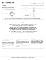
Install
Front Castors
1. Align castors with holes on top and front of
mower and insert (8) 3/8–16 x 19 mm (3/4”)
bolts through mower. Secure with (8) 3/8–16
flange nuts below mower (Fig. 1).
Note: Tighten lower bolts first to pull castor
against front, then top bolts last.
2. Torque bolts to 40–47 Nm (30–35 ft. lb.).
m–3777
Figure 1
1. Front
castor
2. Bolt
3/8–16 x
3/4” (19 mm)
3. Flange
nut 3/8–16
Install
Upper Handle
1. Position handle outside frame and align
mounting holes. Select desired lower mounting
holes for high, medium or low position
according to operators height (Fig. 2).
2. Secure each side with (2) 3/8–16 x 26mm (1”)
bolts and (2) 3/8–16 locknuts (Fig. 2).
3. Torque bolts to 34 Nm (25 ft. lbs.).
m–4213
Figure 2
1. Upper
handle
2.
Rear frame
3.
Bolt 3/8–16 x 1” (26mm)
4.
Locknut 3/8
5. Low
6. High

Assembly
12
Connect Wire Harness
1. Route wire harness inside of frame, along left
handle and over throttle cable. Compress wire
harness covering and press into lower and upper
holes in rear of control panel (Fig. 3).
2. Thread harness up through rear tube of traction
handle (Fig. 3).
Figure 3
1. Wire
harness
2.
Control panel
3. Tube
4.
Wire tie
3. Insert terminals into plastic plug until the clips
snap into position (Fig. 4). If they do not snap
turn around.
4. Push plug onto switch to latch interlock (Fig. 4).
5. Secure wire harness and throttle cable to left
handle, away from PTO lever, with wire tie
(Fig. 3).
m–3782
Figure 4
1. Terminal
2. Clip
3. Plastic
plug
4. Switch
Install Traction Control Rods
1. Thread trunnions equal distance onto each
control rod. For a starting point thread on
approximately 51 mm (2 in.) (Fig. 5).
2. With trunnion rod up, slide clevis pins through
rod fittings and mounting holes in idler brackets
(from outside) (Fig. 5). Secure with 6 mm (1/4”)
washers and hairpin cotters (Fig. 5).
m–3785
Figure 5
1. Control
rod
2. Trunnion
3.
Idler bracket
4.
Clevis pin
5. W
asher 6 mm (1/4” )
6.
Hairpin cotter

Assembly
13
3. Check the gap between upper control bar and
fixed bar with wheel drive fully engaged. Gap
should be approximately 25–32 mm (1 to 1-1/4
in.) (Fig. 6).
Note: The upper control bar and fixed bar
must be parallel in the engaged,
relaxed and brake positions.
4. After completing assembly check operation. If
adjustment is required, remove hairpin cotter
securing rod to upper control bar. Thread rod in
or out of fitting for proper position and install
into upper control bar with hairpin cotter.
5. After adjusting control rods, check parking brake
adjustment, refer to: Brake page 35 for
instructions.
m-4194
Figure 6
1. Control
rod
2.
Fixed control bar
3.
Parking brake lever
4.
Upper control bar
Connect
Throttle Cable
1. Place throttle control lever in FAST detent
position.(Fig. 7).
2. Route cable along left handle, under fuel tank
mount and up to engine throttle base plate.
3. Hook wire Z–bend into hole of speed control
lever (Fig. 7).
4. Loosen cable clamp screw allowing cable
installation, but do not tighten (Fig. 7).
5. Move control cable casing and wire until hole in
speed control lever is aligned with hole in base
plate. Insert a 6.35 mm (1/4 in.) diameter pin or
bolt into aligned holes to hold adjustment.
6. Pull throttle cable slightly to remove any slack
and tighten cable clamp screw to lock
adjustment in place.
7. Remove alignment pin and check control
operation.
m–3787
Figure 7
1. Wire
Z-bend
2.
Speed control lever
3.
Base plate
4.
Alignment holes 6.35mm
(1/4 in.)
5.
Cable clamp

Assembly
14
Install
Blade Control (PT
O)
Rod
1. Rotate blade control lever (PTO) away from left
handle so rod drops down.
2. Remove hairpin cotter from bottom end of blade
control rod (PTO) (Fig. 8).
3. Slide blade control (PTO) rod through hole in
bellcrank and secure with hairpin cotter (Fig. 8).
m–3783
Figure 8
1. Blade
control lever
2.
Blade control rod
3. Bellcrank
4.
Hairpin cotter
Install
Shift Lever
1. Remove the 3/8” locknut and spring disk washer
from the stud on top of the transmission.
Note: Do not remove rubber seal washer and
square hole washer from transmission
shaft.
2. Slide shift lever through control panel and align
mounting hole in lever with square on
transmission shaft. Secure lever to transmission
with previously removed spring washer and
locknut (Fig. 9).
3.
Replace the spring washer
,dish down, and
locknut (Fig. 8).
4. Torque nut to 47 Nm (35 ft. lbs.).
5. Shift lever to second gear and check alignment
of lever in slot of shifter plate. Clearance
between top of lever and the top of the slot
should be about equal to the clearance between
bottom of the lever and the bottom of the slot.
6. If clearance is not correct, remove lever and bend
it slightly to adjust.
Note: Do not bend lever while attached to
transmission shaft or damage may
occur.
7. Shift lever to neutral and check alignment of
lever in slot of shifter plate. Clearance between
left and right of slot should be about equal. If not
move control panel to adjust (Fig. 9).
m–3772
Figure 9
1. Shift
lever
2.
Control panel
3.
Rubber seal washer
4.
Square hole washer
5.
Spring washer
6.
Locknut 3/8

Assembly
15
Mount
Fuel T
ank
1. Align fuel tank to top of rear frame and secure
fuel tank right side with (2) 5/16–18 x 22.5 mm
(7/8 in.) bolts, (2) 5/16 lock washers and (2)
5/16 washers (Fig. 10).
2. Torque bolts to 13 Nm (10 ft. lbs.).
3. Secure fuel tank left side to frame with (2)
5/16–18 x 22.5 mm (7/8 in.) studs, (2) 5/16
washers and (2) 5/16 locknuts (Fig. 10).
4. Tighten nuts until stud threads appear just below
nut.
m–37711
2
3
5
4
6
3
Figure 10
1. Bolt
5/8–18 x 7/8”
(22.5 mm)
2.
Lock washer 5/16
3. W
asher 5/16
4. Stud
5. Spring
6. Locknut
5. Push fuel line onto fuel tank fitting and secure
with hose clamp (Fig. 11).
m–3778
1
23
Figure 1
1
1. Fuel
line
2.
Hose clamp
3.
Fuel fitting

16
Operation
Think
Safety First
Please carefully read all the safety instructions and
symbols in the safety section. Knowing this
information could help you, pets or bystanders avoid
injury.
Controls
Become familiar with all the controls (Fig. 12) before
you start the engine and operate the machine.
Throttle Control – The throttle control has CHOKE,
FAST, SLOW and STOP positions.
Bail – The bail, in conjunction with the PTO switch,
allows the engine to be started with the PTO
disengaged. W
ith the bail compressed the blade
control (PTO) can be engaged. Release the bail with
the PTO engaged and the engine stops.
Blade Control (PTO) – The blade control lever
(PTO) engages and disengages power to the mower
blades. Move the PTO lever forward to engage the
blades. Pull rearward,all the way, to stop driving
mower blades
Gear Shift Lever – Transmission has five forward
speeds, neutral and reverse, and has an in-line shift
pattern. Do not shift while unit is moving, as
transmission damage may occur.
Upper Control Bar – Shift to desired gear and push
forward on control bar to engage forward traction
operation and pull back to brake. Pull right side of
control bar to turn right and left side to turn left.
Lower Contr
ol Bar – Shift transmission to reverse
and pull rearward on lower control bar to engage
rearward traction operation.
Parking Brake Lever – Pull back on upper control
bar and swing brake lever up against the upper handle
to keep brake engaged.
Recoil Starter – Pull recoil starter handle to start
engine.
Fuel Shut–off Valve – (In fuel line) Close fuel
shut–off valve when transporting or storing mower.
2
4
m–4194
1
6
5
7
3
Figure 12
1. Throttle
control
2. Bail
3.
Blade control (PT
O)
4.
Gear shift lever
5.
Upper control bar
6.
Lower control bar
7.
Parking brake lever

Operation
17
Parking Brake
Always set the parking brake when you stop the
machine or leave it unattended.
Setting the Parking Brake
1. Pull the upper control bar rearward and hold it in
this position (Fig. 13).
2. Lift the parking brake lock up and gradually
release the upper control bar (Fig. 13). The brake
lock should stay in the set (locked) position.
Releasing the Parking Brake
1. Pull rearward on the upper control bar (Fig. 13).
Lower the parking brake lock to the released
position.
2. Gradually release the upper control bar.
1
2
m–4212
Figure 13
1. Upper
control bar
2.
Parking brake lock

Operation
18
Starting
and Stopping
the Engine
Starting
1. Make sure spark plug wire(s) are installed on
spark plug(s) and fuel valve is open.
2. Move the blade control to off, the shift lever to
neutral and set the parking brake.
3. Move the throttle control to CHOKE position
before starting a cold engine.
Note: A warm or hot engine usually does not
require any choking. To start a warm
engine, move throttle control to FAST
position.
4. Grasp recoil starter handle firmly and pull out
until positive engagement results; then pull
handle vigorously to start engine. Allow rope to
recoil slowly.
IMPORTANT: Do not pull recoil rope to its
limit or let go of the starter handle when rope
is pulled out because rope may break or recoil
assembly may be damaged.
Stopping
1. Move the throttle lever to “SLOW” (Fig. 14).
Note: If the engine has been working hard or
is hot, let it idle for a minute before
stopping. This helps cool the engine.
In an emergency, the engine may be
stopped by pulling the throttle all the
way back, past SLOW.
2. To stop the engine pull the throttle all the way
back, past SLOW(Fig. 14).
1
2
m–4194
Figure 14
1. Blade
control (PT
O) 2.
Throttle lever
3. Set the parking brake.
4. Pull wire off spark plug(s) to prevent possibility
of accidental starting before storing machine.
5. Close fuel shut off valve before storing machine.
IMPORTANT: Make sure fuel shut off valve
is closed before transporting or storing
machine, or fuel leakage may occur.
/