Page is loading ...

POWER TOWER
IMPORTANT: Read all instructions carefully before using this
product. Retain this owner’s manual for future reference.
The specifications of this product may vary from this photo and, subject
to change without notice.
1720.4-121818


SERVICE ------------------------------------------------------------------------ 2
LABEL PLACEMENT --------------------------------------------------------- 3
PRODUCT SAFETY ---------------------------------------------------------- 4
OVERVIEW DRAWING ------------------------------------------------------ 5
PART LIST ----------------------------------------------------------------------- 6
HARDWARE PACKING LIST & TOOLS --------------------------------- 7
ASSEMBLY --------------------------------------------------------------------- 8
ADJUSTMENT & MAINTENANCE ---------------------------------------- 16
WORKOUT INSTRUCTIONS ---------------------------------------------- 17
WARRANTY --------------------------------------------------------------------- 18
PARTS REQUEST FORM ----------------------------------------------------19
TABLE OF CONTENTS
1

IMPORTANT: FOR NORTH AMERICA ONLY
For damaged or defective products, questions, replacement parts or any
other service support, please contact our customer service department
(Open 8:00 AM - 5:00 PM Pacific Standard Time, Monday thru Friday) by
the below methods:
For Best Service, please Email:
Service@paradigmhw.com
Response Time: 1-2 Business Days
Website:
www.paradigmhw.com
Toll-Free:
1-844-641-7920
Response time may vary.
Please have the following information ready when requesting service:
Your name
Phone number
Model number
Serial number
Part number
Proof of Purchase
Paradigm Health & Wellness, Inc.
1189 Jellick Ave.
City of Industry, CA 91748 USA
SERVICE
2
For damaged or defective products please contact our
customer service before returning to the store.

LABEL PLACEMENT
3

Basic precautions should always be followed, including the following safety
instructions when using this Power Tower. Read all instructions before using
this Power Tower.
1. Read the warning label posted on the Power Tower.
2. Read all the instructions in this manual and do warm up exercises before
using the Power Tower.
3. We recommend that two people be available for assembly of this Power Tower.
4. Keep children away from the Power Tower. Do not allow children to use or
play on the Power Tower. Keep children and pets away from the Power
Tower when it is in use.
5. The Power Tower should be placed on a flat surface when using. Using a
mat or other covering material on the ground is recommended.
6. Set up and operate the Power Tower on a solid level surface. Do not
position the Power Tower on loose rugs or uneven surfaces.
7. This Power Tower is designed for adults only. This product requires a
minimum of 6² feet of space for safe operation.
8. Before using the Power Tower, inspect it for worn or loose components,
and securely tighten or replace any worn or loose components prior to use.
9. If you feel any chest pains, nausea, dizziness, or short of breath, you
should stop exercising immediately and consult your physician before
continuing use.
10. Wear proper clothes and shoes when using this Power Tower; do not wear
clothes that might catch any part of the equipment.
11. Never exercise in bare feet or socks; always wear proper shoes.
12. Be careful to maintain your balance while using, mounting, dismounting, or
assembling the Power Tower, loss of balance may result in a fall and
serious bodily injury.
13. The Power Tower should be used by only one person at a time.
14. Do not use the Power Tower outdoors.
15. This Power Tower is for household use only.
16. WARNING: CANCER AND REPRODUCTIVE
HARM--WWW.P65WARNINGS.CA.GOV.
17. The maximum weight capacity for this product is 275 lbs/125 kgs.
WARNING: Before beginning any exercise program consult your
physician. This is especially important for the people who are over 35 years old
or who have pre-existing health problems. Read all instructions before using any
fitness equipment.
CAUTION: Read all instructions carefully before operating this
product. Retain this Owner’s Manual for future reference.
PRODUCT SAFETY
4

OVERVIEW DRAWING
5

No.
Description
Qty
No.
Description
Qty
01
Left Base Frame
1
17
Washer Ø10.5xØ20x1.5t
19
02
Right Base Frame
1
18
Nylon Lock Nut M10
9
03
Cross Bar
1
19
Round Cap Ø50
2
04
Cross Bar Support Plate
2
20
Bolt M10x25
10
05
Lower Upright Frame
1
21
Curve Washer Ø10.5xØ20x1.5t
2
06
Upright Support Frame
1
22
Curve Washer Ø8.5xØ16x1.5t
6
07
Upper Upright Frame
1
23
Bolt M8x42
2
08
Extend Arm Frame
1
24
Top Frame Round End Cap
2
09
Top Frame
1
25
Bolt M10x174
1
10
Left Pull-up Handle
1
26
Bolt M8x62
6
11
Right Pull-up Handle
1
27
Washer Ø8.5xØ16x1.5t
2
12
Arm Cushion
2
28
Round Plug Ø25
8
13
Back Cushion
1
29
Screw ST4.2x19
1
14
Pin
1
30
Foam Grip Ø23xØ30x120
2
15
Base Frame End Cap
2
31
Foam Grip Ø23xØ30x180
2
16
Bolt M10x70
10
32
Foam Grip Ø23xØ30x145
4
PART LIST
6

HARDWARE PACKING LIST & TOOLS
7

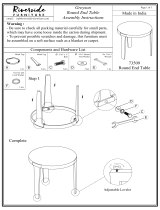
Step1
Position the Cross Bar (3) between the Left and Right Base Frames (1, 2) and align the
bolt holes. Attach the Cross Bar (3) onto both Frames (1, 2) with two Cross Bar Support
Plates (4), four Bolts (16), four Washers (17), and four Nylon Lock Nuts (18). Tighten
bolts and nylon lock nuts with the two 13, 17mm Wrenches
provided.
Hardware:
ASSEMBLY
8
(18) Nylon Lock Nut
4 PCS
(16) Bolt 4 PCS
(4) Cross Bar Support Plate
2 PCS
(17) Washer
4 PCS
13, 17mm Wrench
2 PCS
Tool:

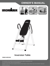
Step 2
Attach the Lower Upright Frame (5) onto the Cross Bar (3) with two Bolts (16), two
Washers (17), and two Nylon Lock Nuts (18). Tighten bolts and nylon lock
nuts with two 13, 17mm Wrenches provided.
Hardware:
.
ASSEMBLY
9
(17) Washer
2 PCS
(18) Nylon Lock Nut
2 PCS
(16) Bolt 2 PCS
13, 17mm Wrench
2 PCS
Tool:

Step 3
Insert the Upper Upright Frame (7) into the Lower Upright Frame (5).
Attach the bottom end of the Upright Support Frame (6) onto the Left/Right Base
Frames (1, 2) with two Bolts (16), two Washers (17), and two Nylon Lock
Nuts (18). Hand tighten only.
Attach the top end of the Upright Support Frame (6) onto the Lower Upright Frame (5)
with six Washers (17) and six Bolts (20). Tighten all bolts and nylon
lock nuts with the two 13, 17mm Wrenches provided.
Hardware:
.
ASSEMBLY
10
(17) Washer
8 PCS
(18) Nylon Lock Nut
2 PCS
(16) Bolt 2 PCS
20) Bolt 6 PCS
13, 17mm Wrench
2 PCS
Tool:

Step 4
Attach both Left/Right Pull-up Handles (10, 11) onto the Top Frame (9) using two Bolts
(16), two Curve Washers (21), two Curve Washers (22), and two Bolts (23). Tighten the
bolts with the two 13, 17mm Wrench and 6mm Allen Wrench provided.
Cover both ends of the Top Frame (9) with two Top Frame Round End Caps (24).
Hardware:
11
ASSEMBLY
(23) Bolt
2 PCS
(21) Curve Washer
2 PCS
(22) Curve Washer
2 PCS
(24) Top Frame Round End Cap
2 PCS
(16) Bolt 2 PCS
6mm Allen Wrench
1 PC
13, 17mm Wrench
2 PCS
Tool:

Step 5
Insert the Top Frame (9) into the Upper Upright Frame (7) and secure using four
Washers (17) and four Bolts (20). Tighten the bolts using the two 13, 17mm Wrenches
provided.
Hardware:
12
ASSEMBLY
(20) Bolt 4 PCS
(17) Washer
1 PC
13, 17mm Wrench
2 PCS
Tool:

Step 6
Position the Extend Arm Frame (8) onto the Upper Upright Frame (7) and align bolt
Holes. Attach the Extend Arm Frame (8) onto the Upper Upright Frame (7) with one Bolt
(25), one Washer (17), and one Nylon Lock Nut (18). Tighten the bolt and nylon lock nut
with the two 13, 17mm Wrenches provided.
Hardware:
13
ASSEMBLY
(17) Washer
1 PC
(18) Nylon Lock Nut
1 PC
(25) Bolt 1 PC
13, 17mm Wrench
2 PCS
Tool:

Step 7
Attach two Arm Cushions (12) onto the Extend Arm Frame (8) with four Bolts (26) and
four Curve Washers (22). Tighten the bolts with the two 13, 17mm Wrenches provided.
Hardware:
14
ASSEMBLY
(22) Curve Washer
4 PCS
(26) Bolt 4 PCS
13, 17mm Wrench
2 PCS
Tool:

Step 8
Pull the Extend Arm Frame (8) up, and insert the Pin (14) into the holes on the Extend
Arm Frame (8) and Upper Upright Frame (7) to lock the Extend Arm Frame (8) in place.
Attach the Back Cushion (13) onto the Upright Frame (7) with two Bolts (26) and two
Washers (27). Tighten bolts with two 13, 17mm Wrenches provided.
Hardware:
15
ASSEMBLY
(26) Bolt 2 PCS
(27) Washer
2 PCS
13, 17mm Wrench
2 PCS
Tool:

ADJUSTING THE EXTEND ARM FRAME
The Extend Arm Frame (8) can folded back to perform pull ups. Pull the Extend Arm
Frame (8) up, and insert the Pin (14) into the holes on the Extend Arm Frame (8) and
Upper Upright Frame (7) to lock the Extend Arm Frame (8) in place.
MAINTENCE
The Power Tower can be cleaned with a soft cloth. Wipe your perspiration off
the Power Tower after each use. Inspect all assembly bolts on the Power Tower for
proper tightness every week. Replace missing nuts and bolts. Securely tighten loose
nuts and bolts. Worn or damaged components should be replaced immediately before
use.
ADJUSTMENT & MAINTENCE
16

Dip Exercise:
To do the dip exercise, the user hangs from the Extend
Arm Frame with their arms straight and shoulders over their
hands, then lowers their body until their arms are bent to a
90 degree angle, and then lifts his/her body up, returning to
the starting position.
User must keep the body as straight as possible, without
leaning forward.
Push-up Exercise:
While grasping the handles on both Left/Right Base
Frames and keeping the body straight throughout the
exercise, lower the body until the upper arms are at least
parallel to the ground. Then, push yourself up to the initial
position by completely straightening the arms.
Pull-up Exercise:
Grasp both Left/Right Pull-up Handles with both hands.
Then pull your body up and finished by lowering the body
until arms and shoulders are fully extended.
Vertical Knee Raise Exercise:
To do the vertical knee raise exercise, stand in between
the Extend Arm Frame and lean against the Back Cushion.
Place both arms on the Arm Cushions and grasp both
handles on the Extend Arm Frame. Raise yourself up so
that all your body weight is supported by your arms and
your legs can hang straight, or slightly bent. Raise your
knees all the way up as far as you can comfortably manage,
without allowing your body to swing. Slowly lower your
knees back.
WORKOUT INSTRUCTIONS
17

MANUFACTURER’S LIMITED WARRANTY
Paradigm Health & Wellness warrants to the original purchaser that this product is free from defects in
material and workmanship when used for the purpose intended, under the conditions that it has been
installed and operated in accordance with Paradigm’s Owner’s Manual. Paradigm’s obligation under
this warranty applies to the following:
COMPONENT LENGTH OF WARRANTY
Structural Frame 1 year For Home Use Only
All Other Components 90 days For Home Use Only
Exclusions from Warranty Coverage:
Paradigm does not warrant against and is not responsible for, and no implied warranty shall be
deemed to cover, any product failure, product malfunction, or damages attributable to:
1. Improper installation and/or failure to abide by Paradigm’s installation guidelines;
2. Use of this product beyond normal home use, or in an application for which it was not designed;
3. Cosmetic items such as scratches, dents or discolorations;
4. Damage caused by normal wear and tear, vandalism, accidental or by animals;
5. Any act of Nature (such as fire, flooding, snow, ice, hurricane, earthquake, lightning or other natural disaster),
environmental condition (such as air pollution, mold, mildew, etc.), or staining from foreign substances (such as dirt,
grease, oil, etc.);
6. Normal weathering due to exposure to sunlight, weather and atmosphere which can cause colored surfaces to, among
other things, flake, chalk, accumulate dirt or stains.
7. Improper operation, alteration, handling, storage, abuse or neglect of the products.
Paradigm, using its sole discretion, will either repair or replace free of charge any part(s) proven to be
defective under normal home use. Any repair or replacement shall provide no new warranty coverage,
but shall retain only the remaining portion of the original product’s warranty. This warranty is offered
only to the original purchaser and is not transferable. Proof of original purchase is required.
Ordering Replacement Parts
Replacement parts can be ordered by emailing our customer service department:
Service@paradigmhw.com
Open Monday thru Friday 8:00 AM - 5:00 PM (PST).
When ordering replacement parts please have the following information ready:
1. Owner’s Manual
2. Model Number
3. Description of Parts
4. Part Number
5. Date of Purchase
WARRANTY
18
/