Page is loading ...

KFMI ICE CHUTE
EXTENSION KIT

Installation Instructions
Purpose of the kit:
To allow the installation of a NME or FME series single discharge ice machine up to 8 feet
above the storage bin (multiple discharge units require 2 kits). For example, the ice machine
could be placed on top of a walk-in cooler and the ice storage bin inside the cooler.
WARNING: The Structure For The Ice
Machine Must Be Designed To Support
The Weight Of The Ice Machine. The
location must also meet the requirements for
temperature and serviceability as described
in the service manual for the ice machine.
Included with the kit:
1. Tubing connection for the ice machine.
2. Tubing connection for the storage bin.
3. Electric eye extension wires.
Not included is the tubing, which must be
N.S.F. approved 6" dia. schedule 40 PVC,
maximum length of 8’.
To Install:
1. Determine the location of
the ice storage bin. The ice
discharge tube should enter
the ice storage bin as near to
the center of the bin as
possible.
2. From the location of the
storage bin, determine the
location of the ice machine. It
must be directly above the ice
storage bin - no slope is
allowed in the ice chute.
3. Cut a 8" diameter hole in
the top of the room where the
ice machine chute will be.
4. Determine the connecting
tube length:
• A. Measure the distance
from the outside of the
room top panel to the ice
storage bin top.
• B. Subtract 3" from that measurement to
obtain the length of tubing needed.
5. Cut the PVC tube to the correct length.
6. Insert the connecting tube thru the hole
from below.
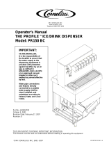
ICE
MACHINE
CONTROL
BOX
ICE
CHUTE
WOODEN
SPACER
TOP
UPPER
COLLAR
CONNECTING
PIPE
ICE STORAGE
BIN CONNECTION
STORAGE BIN
WIRE
FRONT VIEW OF INSTALLED KIT & ICE MACHINE
HOLE IN TOP
HOLE IN
SIDE
PANEL

7. Use PVC solvent to fasten the upper
collar to the tubing.
8. Install the ice storage bin connection onto
the tube using PVC solvent.
9. Cut a 7" diameter hole into the ice storage
bin top, and place the ice storage bin
connection into the ice storage bin top.
10. Have a pressure treated 2 x 4 ripped into
a 1 1/4" wide strip, cut two 2’ lengths from
that strip.
11. Place the two 2’ lengths on the top of the
room where the ice machine will be.
12. Place a large bead of food grade silastic
sealant onto the top of the collar.
13. Install the ice machine onto the collar
and wooden spacers. Center the ice
machine’s chute over the center of the collar.
14. Install the ice machine per the normal
instructions in the service manual for the ice
machine.
ICE
MACHINE
CONTROL
BOX
WOODEN
SPACER
TOP
UPPER
COLLAR
CONNECTING
PIPE
ICE STORAGE
BIN CONNECTION
STORAGE
CART
WIRE
FRONT VIEW WHEN USING A CART
HOLE IN TOP
HOLE IN
SIDE
PANEL
BRACKET TO
CONNECT TUBE
TO WALL
Instructions Continued
Note: When using a cart instead of a fixed storage bin, the connecting pipe will require an
additional bracket to secure it to a nearby wall. Bracket is not included with the kit.

WARNING: Disconnect Electrical Power
Before Continuing.
15. Remove the electric eyes from the ice
machine.
A. Remove the front panel and the control
box cover.
B. Slide the electric eyes out of their
positions at the bottom of the ice chute.
C. Tracing the wires, disconnect the electric
eyes from the circuit board.
16. Mount the electric eyes onto the lower
end of the ice chute. Note: the eyes have a
sloped housing, designed to drain any water
away from the eyes, be sure that the eyes
are mounted sloped side down.
17. Cut a 1" dia. hole in the left side panel of
the ice machine, just below the control box
(FME2404 & NME1854 place a hole on each
end of the machine).
18. Cut a 1" dia. hole in the top of the room,
just to the left of the ice machine (FME2404
& NME1854 place another hole just to the
right of the ice machine).
19. Install snap bushings into hole made in
the side panel.
20. Route the extension wires through the
back of the control box, to the ice machine’s
circuit board (where the electric eyes were)
and then route through the room top to the
blue box on the bottom of the ice chute.
21. Inside the blue box, connect the electric
eyes to the extension wires, and to the
toggle switch. Seal the hole in the bottom of
the blue juction box.
22. Seal the hole in the room’s top where
the wires passed through.
23. This completes the basic installation.
The ice maker will shut off when the electric
eyes have ice between them, or when the
toggle switch is moved to OFF.
Note: Some ice will continue to fall for about
2 minutes after the toggle switch is moved to
OFF.
17-2075-01 Rev. A
BOTTOM END OF KIT
CIRCUIT BOARD
IN ICE MACHINE
CONNECT HERE,
SEAL AT
BOTTOM WITH
SEALANT
ELECTRIC EYE
FROM ICE
MACHINE
1/4