
I n s t a l l a t i o n G u i d e
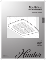
90050/90051/90059 Spa Select
™
Bath Ventilator Fan
41717-01 05/31/2006
ENGLISH
See page 2
ESpañoL
Vea la página 15
41717-EngS_05.31.06.indd 1 5/31/06 3:53:11 PM

2
DISCONNECT
ELECTRIC
POWER SUPPLY
AND LOCK OUT
SERVICE PANEL
BEFORE
SERVICING UNIT
W a r n i n g
TO REDUCE THE RISK OF ELECTRIC SHOCK OR INJURY, OBSERVE THE FOLLOWING:
1. For general ventilating use only. Do not use for ventilat-
ing hazardous or explosive materials.
2. To avoid motor bearing damage and noisy/unbalanced
impellers, keep drywall spray, construction dust, etc.
off power unit.
3. DO NOT install this product in a wall. This product is
designed for installation in ceilings up to a 12/12 pitch
(45 degrees). Ductwork must point upward.
4. Please read specification label on product for further
information and requirements.
PREVENTATIVE MAINTENANCE
A clean fan provides better service. Disconnect the power supply and clean the fan as listed below.
TO CLEAN GRILLE: Use a mild detergent, such as dishwashing liquid, and a soft cloth. DO NOT use abrasive cloths, steel
wool pads or scouring powders.
TO CLEAN FAN ASSEMBLY: Unplug motor cord from receptacle. To remove motor plate, find the single tab on the motor
plate (located next to the receptacle). Push up rear motor plate tab while pushing out on the side of the housing or insert a
screwdriver into the slot in the housing (next to tab) and twist screwdriver. Gently vacuum fan, motor and interior of housing.
METAL AND ELECTRICAL PARTS SHOULD NEVER BE IMMERSED IN WATER.
MAINTENANCE
The motor is permanently lubricated and never needs oiling. If the motor bearings are making excessive or unusual
noises, replace the motor with the exact service motor. You should replace the impeller at the same time.
C a U T i O n
W a r n i n g
1. Use this unit only in a manner intended by the manufacturer.
If you have questions, contact the manufacturer at the phone
number or address listed in the warranty.
2. Before installing, servicing, or cleaning the unit,
disconnect the power by turning off the circuit breakers to
the outlet box and associated wall switch location. If you
cannot lock the circuit breakers in the off position, securely
attach a prominent warning device, such as a tag, to the
service panel.
3. Installation work and electrical wiring must be done by
qualified person(s) in accordance with all applicable codes
and standards, including fire-rated construction codes and
standards.
4. Sufficient air is needed for proper combustion and exhaust-
ing of gasses through the flue (chimney) of fuel burning
equipment to prevent backdrafting. Follow the heating
equipment manufacturer’s guideline and safety standards,
such as those published by the National Fire Prevention
Association (NFPA), and the American Society for Heating,
Refrigeration and Air-Conditioning Engineers (ASHRAE), and
the local code authorities.
5. When cutting or drilling into wall(s) or ceiling, do not
damage electrical wiring or other hidden utilities.
6. Ducted fans must always be vented to the outdoors. Keep
ducting as short and as straight as possible.
7. Acceptable for use over a bathtub or shower when
connected to a GFCI protected branch circuit.
8. Install fan at least 5 feet (1.52 m) above the floor.
9. Never place a switch where it can be reached from a tub
or shower.
10. This unit must be grounded.
41717-01 05/31/2006 41717-01 05/31/2006
41717-EngS_05.31.06.indd 2 5/31/06 3:53:11 PM

3
D
95047-01-000
E
03242-07-133
F
G
95374-01-000
I
94998-01/02-000
75192-01-000
3/8" Cable Connector
Extra Screws
A
*
B
*
*
NOTE:
Strain relief cable connector
must be installed. Not Included.
x2
H
74508-03-133
x3
C
x2
H
Included.
Turn off the power source.
D
95047-01-000
E
03242-07-133
F
G
95374-01-000
I
94998-01/02-000
75192-01-000
3/8" Cable Connector
Extra Screws
A
*
B
*
*
NOTE:
Strain relief cable connector
must be installed. Not Included.
x2
H
74508-03-133
x3
C
x2
H
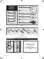
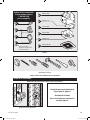
Tools Needed.
Estimated assembly time: 30 to 60 minutes
Before Installation
Check all the parts.
If damaged, call
1-888-830-1326
for replacements.
New construction installation
Go to Step A1, page 4
Existing construction
Go to Existing Construction Installation,
page 8
41717-01 05/31/2006 41717-01 05/31/2006
NOTE: Remove all packing materials before installation
41717-EngS_05.31.06.indd 3 5/31/06 3:53:13 PM

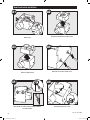
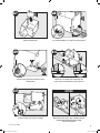
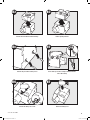
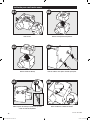
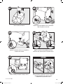
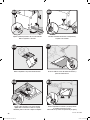
A1
D
Back out the pre-loaded screw tips until flush with the
side of the housing.
Remove the motor/blower from the housing.
Remove the wiring cover screw.
4
Remove packing material.
A2
A3
A6
E
Remove tape.
A4
A5
Remove the pre-loaded screw tip covers.
New Construction Installation
41717-01 05/31/2006 41717-01 05/31/2006
41717-EngS_05.31.06.indd 4 5/31/06 3:53:15 PM

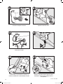
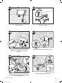
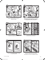
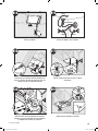
A7
F
A8
D
A9
B
C
A10
D
5/8
1/2
5/8
1/2
A11
OPTION
Remove the wiring cover. Pop out the first wiring access slug. Use second if needed.
Insert the strain relief into the housing and secure
with the washer.
Position the correct depth mark at the bottom edge
of the joist–based on the thickness of your sheet rock.
Screw pre-loaded screws into joist or framing. Nail the tabs on both sides to joist or framing so that the
housing will be flush with the finished ceiling.
Nails are not provided.
5
41717-01 05/31/2006 41717-01 05/31/2006
41717-EngS_05.31.06.indd 5 5/31/06 3:53:18 PM

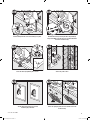
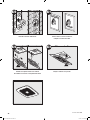
0
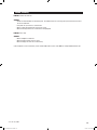
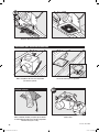
A17
D
A12
A13
A
A
A
Green
Black White
Bare Copper
Ground
A14
B
D
A16
F
Pull the wires through the strain relief. Tighten the strain relief screws.
Connect wires as shown.
Connect a 4” duct and vent to the outside. Tape joints.
If ducting does not fit securely, an adapter may need
to be purchased.
Install the wiring cover plate. Make sure all wiring con-
nections are inside the box or under the wiring cover plate.
6
F
A15
B
D
41717-01 05/31/2006 41717-01 05/31/2006
41717-EngS_05.31.06.indd 6 5/31/06 3:53:21 PM

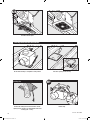
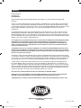
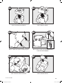
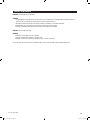
I
A23
0000
D
A18
G
0000
G
D
A19
A21
ON
OF
F
A22
Connect wiring from the motor to the wiring cover plate.
Reinstall the motor by inserting the tabs and pushing up
into position. Make sure the wires are not pinched between
the motor and the housing.
Secure the motor by tightening the 2 screws.
Turn on the power source.
Test the motor. If the motor does not run,
check the plug connection.
7
A20
H
Insert one spring clip of the fan cover into the slot on the
motor housing.
41717-01 05/31/2006 41717-01 05/31/2006
41717-EngS_05.31.06.indd 7 5/31/06 3:53:24 PM

B1
D
7.25
”
7.75
”
D
Cut out an opening for the housing.
Use the motor housing as a template to mark position.
Remove the existing fan and check to make sure the
opening is large enough to accommodate the new motor
housing (7.25” x 7.75”).
Existing Construction Installation
Existing Fan
8
Remove tape.
A24
I
Push the cover into place.
41717-01 05/31/2006 41717-01 05/31/2006
41717-EngS_05.31.06.indd 8 5/31/06 3:53:27 PM

B2
B3
B6
E
B7
F
Remove packing material.
Remove the wiring cover screw. Remove the wiring cover.
9
B4
B5
Back out the pre-loaded screw tips until flush with the
side of the housing.
Remove the pre-loaded screw tip covers.
Remove the motor/blower from the housing.
41717-01 05/31/2006 41717-01 05/31/2006
41717-EngS_05.31.06.indd 9 5/31/06 3:53:29 PM

B8
D
Pull the wires through the strain relief and tighten the
strain relief screws.
B9
B
C
D
B10
B11
2
1
B12
D
B13
10
Fit housing into the opening and secure by tightening the
pre-loaded screws into the joist.
Note: Install the box flush with the sheetrock (ceiling).
Insert the strain relief into the housing and secure
with the washer.
Move the housing into position above the ceiling.
Pop out the first wiring access slug. Use second if needed.
41717-01 05/31/2006 41717-01 05/31/2006
Attach existing ducting to duct connector. Tape joints.
If ducting does not fit securely,
an adapter may need to be purchased.
41717-EngS_05.31.06.indd 10 5/31/06 3:53:32 PM

D
F
E
B16
D
B14
A
A
A
Green
Black White
Bare Copper
Ground
B15
B
D
D
B17
0000
G
D
B18
Install the wiring cover plate. Make sure all wiring
connections are inside the box or under the wiring
cover plate.
Connect wiring from the motor to the wiring cover plate.
Reinstall the motor by inserting the tabs and pushing up
into position. Make sure the wires are not pinched between
the motor and the housing.
11
Connect the wiring. Connect wires as shown.
H
B19
Secure the motor by tightening the 2 screws.
41717-01 05/31/2006 41717-01 05/31/2006
41717-EngS_05.31.06.indd 11 5/31/06 3:53:35 PM

B20
ON
OF
F
B21
I
B22
12
B23
I
Push the cover into place.
Insert one spring clip of the fan cover into the slot
on the motor housing.
Test the motor. If the motor does not run,
check the plug connection.
Turn on the power source.
41717-01 05/31/2006 41717-01 05/31/2006
41717-EngS_05.31.06.indd 12 5/31/06 3:53:37 PM

13
Trouble Shooting
Problem: Fan does not come on.
Solution:
• Hunter Fan Bath Ventilators are extremely quiet. To confirm that the fan is running, place your hand near the vents to
feel the air movement.
• Turn power on, replace fuse, or reset breaker.
• Check all plug connections to be sure they are secure.
• Check the wiring to make sure it matches the wiring diagram.
Problem: Fan is noisy.
Solution:
• Check and tighten all fasteners.
• Check the glass to make sure it is secure.
• Check the flapper to make sure it moves freely.
If you need parts or service assistance, please call 888-830-1326 or visit us at our WEB site at http://www.hunterfan.com.
41717-01 05/31/2006 41717-01 05/31/2006
41717-EngS_05.31.06.indd 13 5/31/06 3:53:37 PM

2500 Frisco Avenue, Memphis, Tennessee 38114
Printed in China
Warranty
41717-01 05/31/2006
Hunter Fan Company
Bath Exhaust Fan
LIMITED WARRANTY
Hunter Fan Company makes the following limited warranty to the original user or consumer purchaser of this Hunter bath
exhaust fan:
If any part of your Hunter bath exhaust fan (except for glass fixtures and light bulbs) fails at any time within one year after the date
of sale to you due to a defect in material or workmanship, we will repair or, at our option, replace the defective part free of charge
for parts and labor performed at our nearest service center or at our Service Department in Memphis, Tennessee. After this one-year
period, you will be responsible for all parts and labor costs for repairs on the bath exhaust fan except for motor repairs as
provided below.
If your Hunter bath exhaust fan motor fails at any time within five years after the date of sale to you due to a defect in material or
workmanship, labor and materials to repair the defect will be provided free of charge at our nearest service center or our Service
Department in Memphis, Tennessee. If no replacement part can be provided, we will, at our option, either refund the actual purchase
price of your bath exhaust fan or provide a replacement free of charge. After this five-year period, you will be responsible for all parts
and labor costs for repairs on all parts of the bath exhaust fan.
IF THE ORIGINAL USER OR CONSUMER PURCHASER CEASES TO OWN THE FAN, THIS WARRANTY AND ANY IMPLIED WARRANTY WHICH
THEN REMAINS IN EFFECT, INCLUDING BUT NOT LIMITED TO ANY IMPLIED WARRANTY OF MERCHANTABILITY OR FITNESS FOR A
PARTICULAR PURPOSE, ARE VOIDED. NO WARRANTY, EXPRESS OR IMPLIED, INCLUDING ANY WARRANTY OF MERCHANTABILITY OR
FITNESS FOR A PARTICULAR PURPOSE, IS MADE IN RESPECT OF GLASS FIXTURES OR LIGHT BULBS OR THE FINISH ON ANY METAL
PORTION OF THE BATH EXHAUST FAN.
THIS WARRANTY IS IN LIEU OF ALL OTHER EXPRESS WARRANTIES. THE DURATION OF ANY IMPLIED WARRANTY, INCLUDING, BUT NOT
LIMITED TO, ANY IMPLIED WARRANTY OF MERCHANTABILITY OR FITNESS FOR A PARTICULAR PURPOSE, IN RESPECT TO ANY HUNTER
FAN BATH EXHAUST FAN MOTOR OR OTHER FAN PART, IS EXPRESSLY LIMITED TO THE PERIOD OF THE EXPRESS WARRANTY SET FORTH
ABOVE FOR SUCH MOTORS OR OTHER PARTS.
This warranty is voided if your Hunter bath exhaust fan is not purchased and installed in the U.S.A. This warranty excludes and does
not cover defects, malfunctions or failures of any Hunter bath exhaust fan which were caused by repairs by persons not authorized by
us, use of parts or accessories not authorized by us, mishandling, improper installation, modifications or damage to the Hunter bath
exhaust fan while in your possession, or unreasonable use, including failure to provide reasonable and necessary maintenance.
To obtain servicing, contact the nearest Hunter authorized service center of the Hunter Fan Company Service Department, 2500
Frisco Avenue, Memphis, Tennessee 38114. Please contact us before shipping your bath exhaust fan to us. If we authorize you to
ship it to us, you will be responsible for all insurance and freight or other transportation charges to our factory or service center. We
will return your Hunter bath exhaust fan freight prepaid. Your Hunter bath exhaust fan should be properly packed to avoid damage in
transit since we will not be responsible for any such damage. Proof of purchase is required when requesting warranty service. The
purchaser must present the sales receipt or other document that establishes proof of purchase.
IN NO EVENT SHALL HUNTER FAN COMPANY BE LIABLE FOR CONSEQUENTIAL OR INCIDENTAL DAMAGES.
SOME STATES DO NOT ALLOW LIMITATIONS ON HOW LONG AN IMPLIED WARRANTY LASTS OR THE EXCLUSION OR LIMITATION OF
INCIDENTAL OR CONSEQUENTIAL DAMAGES SO THE ABOVE LIMITATION OR EXCLUSIONS MAY NOT APPLY TO YOU.
THE WARRANTY GIVES YOU SPECIFIC LEGAL RIGHTS AND YOU MAY ALSO HAVE OTHER RIGHTS WHICH VARY FROM STATE TO STATE
.
14
41717-EngS_05.31.06.indd 14 5/31/06 3:53:38 PM

DESDE
G u í a d e i n s t a l a c i ó n
Ventilador para baño 90050/90051/90059 Spa Select
™
41717-02 05/31/2006
Español
15
41717-Span_05.31.06.indd 15 5/31/06 3:54:37 PM

16
DESCONECTE LA
ALIMENTACIÓN
ELÉCTRICA Y
CIERRE EL PANEL
DE SERVICIO
ANTES DE DAR
MANTENIMIENTO
A LA UNIDAD
tc.Retire las cubiertas de las puntas de tornillo precargadas.
A D V E R T E N C I A
PARA REDUCIR EL RIESGO DE DESCARGA ELÉCTRICA O LESIONES, OBSERVE LO SIGUIENTE:
1. Sólo para uso de ventilación general. No lo utilice para
ventilar ambientes con materiales peligrosos o explosivos.
2. Para evitar daños a los rodamientos del motor e impulsores
ruidosos o desbalanceados, mantenga la unidad de
potencia lejos de la aplicación de aerosol para paneles
de yeso (drywall), polvo de la construcción, etc.
3. NO instale este producto en una pared. Este producto
está diseñado para instalarse en techos con una
inclinación de hasta 12/12 (45º). La red de ductos debe
dirigirse hacia arriba.
4. Vea más información y los requisitos en la etiqueta de
especificación del producto.
MANTENIMIENTO PREVENTIVO
Un ventilador limpio proporciona mejor servicio. Desconecte la alimentación y limpie el ventilador como se indica a continuación.
PARA LIMPIAR LA REJILLA: Use un detergente suave, como líquido para lavado de platos, y un paño suave. NO emplee paños
abrasivos, almohadillas de lana de acero ni polvos para fregar.
PARA LIMPIAR EL CONJUNTO DEL VENTILADOR:
Desconecte el cordón del motor de la toma de corriente. Para retirar la placa del motor, encuentre la pestaña en la
placa (ubicada junto a la toma de corriente). Levante la pestaña posterior de la placa del motor mientras empuja
hacia afuera en el lado del alojamiento o introduzca un destornillador en la ranura del alojamiento (junto a la pestaña)
y gire el destornillador. Suavemente aspire el ventilador, el motor y el interior del alojamiento.
LAS PARTES METÁLICAS ELÉCTRICAS NUNCA DEBEN SUMERGIRSE EN AGUA.
MANTENIMIENTO
El motor está lubricado permanentemente y no necesita ser engrasado. Si los rodamientos del motor hacen ruidos excesivos
o inusuales, reemplace el motor con el motor de servicio exacto. Debe reemplazar el impulsor al mismo tiempo.
PRECAUCIÓN
ADVERTENCIA
1. Utilice esta unidad sólo de la manera indicada por el fabricante.
Si tiene alguna pregunta, contacte con el fabricante en el
teléfono o la dirección indicados en la garantía.
2. Antes de instalar, dar servicio o limpiar la unidad, desco-
necte la alimentación eléctrica apagando los interruptores
automáticos que alimentan la caja de salida y al interruptor
de pared respectivo. Si no puede bloquear los interruptores
automáticos en la posición de apagado, fije firmemente una
forma destacada de advertencia, como una etiqueta de
seguridad, en el tablero de servicio.
3. Los trabajos de instalación y cableado eléctrico deben ser
realizados por personas calificadas de acuerdo con todos los
códigos y las normas aplicables, incluyendo los códigos y
normas de construcción contra incendio.
4. Se necesita aire suficiente para una combustión adecuada y
para evacuar los gases por el tubo de la chimenea de equipo
que quema combustible a fin de evitar el flujo inverso. Siga
las pautas del fabricante del equipo de calefacción y las
normas de seguridad, como las de la Asociación Nacional de
Protección contra Incendios (NFPA), la Asociación de Ingenieros
Americanos en Calefacción y Aire acondicionado (ASHRAE), y
los códigos locales.
5. Al cortar o taladrar en paredes o techo, no dañe el cableado
eléctrico u otros servicios no visibles.
6. Los ventiladores canalizados siempre deben descargar al aire
libre. Mantenga los ductos tan cortos y rectos como sea posible.
7. Aceptable para uso sobre una bañera o ducha si se conecta
en un circuito derivado protegido por un interruptor
automático de falla a tierra (GFCI).
8. Instale el ventilador por lo menos a 5 pies (1.52 m) por
encima del piso.
9. Nunca coloque un interruptor donde pueda ser alcanzado
desde una tina o una ducha.
10. Esta unidad debe ponerse a tierra.
41717-02 05/31/2006 41717-02 05/31/2006
41717-Span_05.31.06.indd 16 5/31/06 3:54:38 PM

17
D
95047-01-000
E
03242-07-133
F
G
95374-01-000
I
94998-01/02-000
75192-01-000
x2
H
74508-03-133
Conector de cable de 3/8”
*
NOTA:
Debe estar instalado el
manguito de alivio de tensión
del cable. No incluido.
x4
*
*
A
B
C
Tornillos adicionales
x2
I
Incluido.
Apague la fuente de alimentación.
D
95047-01-000
E
03242-07-133
F
G
95374-01-000
I
95018-01/02-000
75192-01-000
3/8" Cable Connector
Extra Screws
A
*
B
*
*
NOTE:
Strain relief cable connector
must be installed. Not Included.
x2
H
74508-03-133
x3
C
x2
H
Herramientas necesarias.
Tiempo estimado de ensamblaje: entre 30 y 60 minutos
Antes de la instalación
Verifique todos los componentes.
Si están dañados, llame al
1-888-830-1326
para un reemplazo.
Instalación para construcción nueva
Vaya al paso A1, página 4
Construcción existente
Vaya a Instalación para construcción
existente, página 8
NOTA: Retire todo el material de embalaje antes de la instalación.
41717-02 05/31/2006 41717-02 05/31/2006
41717-Span_05.31.06.indd 17 5/31/06 3:54:40 PM

A1
D
Retire las puntas de tornillo precargadas hasta que estén
a nivel con el lado del alojamiento.
Retire el motor/soplador del alojamiento.
Retire el tornillo de la cubierta del cableado.
18
A2
A3
A6
E
Retire la cinta.
A4
A5
Retire las cubiertas de las puntas de tornillo precargadas.
Instalación para construcción nueva
Retire el material de embalaje.
41717-02 05/31/2006 41717-02 05/31/2006
41717-Span_05.31.06.indd 18 5/31/06 3:54:42 PM

A7
F
A8
D
A9
B
C
A10
D
5/8
1/2
5/8
1/2
A11
OPCIÓN
Retire la cubierta del cableado. Expulse el primer tapón metálico de acceso del cableado.
Utilice el segundo si es necesario.
Introduzca el aliviador de tensiones en el alojamiento y
asegúrelo con la arandela.
Ubique la correcta marca de profundidad en el borde
inferior de la viga, según el espesor de su plancha de yeso.
Instale los tornillos precargados en la viga o el marco.
Clave las pestañas en ambos lados a la viga o al marco de
modo que el alojamiento esté a nivel con el techo
terminado. No se proporcionan los clavos.
19
41717-02 05/31/2006 41717-02 05/31/2006
41717-Span_05.31.06.indd 19 5/31/06 3:54:45 PM

0
A17
D
A12
A13
A
A
A
Verde
Negro Blanco
Cobre desnudo
Tierra
A14
B
D
A16
F
Tire de los alambres por el aliviador de tensiones. Apriete los tornillos del aliviador de tensiones.
Conecte los alambres como se muestra.
Conecte un ducto de 4” y ventile hacia el exterior. Aplique
cinta a las uniones. Si el ducto no se ajusta firmemente,
puede ser necesario comprar un adaptador.
Instale la placa de cubierta del cableado. Asegúrese que
todas las conexiones de cableado estén dentro de la caja
o debajo de la placa de cubierta del cableado.
20
F
A15
B
D
41717-02 05/31/2006 41717-02 05/31/2006
41717-Span_05.31.06.indd 20 5/31/06 3:54:48 PM
Page is loading ...
Page is loading ...
Page is loading ...
Page is loading ...
Page is loading ...
Page is loading ...
Page is loading ...
Page is loading ...
-
 1
1
-
 2
2
-
 3
3
-
 4
4
-
 5
5
-
 6
6
-
 7
7
-
 8
8
-
 9
9
-
 10
10
-
 11
11
-
 12
12
-
 13
13
-
 14
14
-
 15
15
-
 16
16
-
 17
17
-
 18
18
-
 19
19
-
 20
20
-
 21
21
-
 22
22
-
 23
23
-
 24
24
-
 25
25
-
 26
26
-
 27
27
-
 28
28


Hunter Fan SPA SELECT 90050 User manual
- Type
- User manual
Ask a question and I''ll find the answer in the document
Finding information in a document is now easier with AI
in other languages
Related papers
-
 Hunter Fan 90051 Owner's manual
-
 Hunter Fan 90050 Owner's manual
-
 Hunter Fan 27179 User manual
-
 Hunter Fan 81005 User manual
-
 Hunter Fan 20091104 User manual
-
 Hunter Fan 82021 Owner's manual
-
 Hunter Fan 82043 User manual
-
 Hunter Fan Ventilation Hood 90052 User manual
-
 Hunter Fan 82007 User manual
-
 Hunter Fan 82005 Owner's manual


Other documents
-
Hunter 80200A Installation guide
-
Hunter 90052 Installation guide
-
-
-
Philips SWV2085W User manual
-
-
-
-
 Hunter Home Comfort 81030 User manual
-
