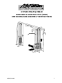
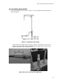
Life Fitness SM41 is a versatile and durable multi-gym designed for intense strength training workouts. With four weight stacks ranging from 150 to 300 pounds, it offers a wide resistance range for users of all fitness levels. The high and low pulley system allows for a variety of exercises targeting different muscle groups, including the chest, back, shoulders, and arms. The lat bench and adjustable tricep top provide comfortable support and positioning for various exercises.
Life Fitness SM41 is a versatile and durable multi-gym designed for intense strength training workouts. With four weight stacks ranging from 150 to 300 pounds, it offers a wide resistance range for users of all fitness levels. The high and low pulley system allows for a variety of exercises targeting different muscle groups, including the chest, back, shoulders, and arms. The lat bench and adjustable tricep top provide comfortable support and positioning for various exercises.


-
 1
1
-
 2
2
-
 3
3
-
 4
4
-
 5
5
-
 6
6
-
 7
7
-
 8
8
-
 9
9
-
 10
10
-
 11
11
-
 12
12
-
 13
13
-
 14
14
-
 15
15
-
 16
16
-
 17
17
-
 18
18
-
 19
19
-
 20
20
-
 21
21


Life Fitness SM41 is a versatile and durable multi-gym designed for intense strength training workouts. With four weight stacks ranging from 150 to 300 pounds, it offers a wide resistance range for users of all fitness levels. The high and low pulley system allows for a variety of exercises targeting different muscle groups, including the chest, back, shoulders, and arms. The lat bench and adjustable tricep top provide comfortable support and positioning for various exercises.
Ask a question and I''ll find the answer in the document
Finding information in a document is now easier with AI
Related papers
Other documents
-
Trex Outdoor Furniture TX3810-11CB Operating instructions
-
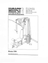 HoistFitness H-550 Owner's manual
-
Keys Fitness KPS-2250 User manual
-
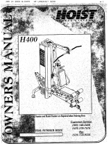 HoistFitness H-400 Owner's manual
-
Hoist Fitness H-300 User manual
-
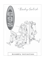 Body Solid G9S Assembly Instructions Manual
-
-
-
 HoistFitness H-500 Owner's manual
-
CYBEX MG 500 Owner's And Service Manual


