Page is loading ...

1411 S. Roselle Rd. Schaumburg, IL 60193
Phone (847) 923-0002
Fax (847) 923-0004
www.AltronicsInc.com
INTEGRATED ELECTRONIC SAFE SHIFTING SYSTEM
Patents Pending
INSTRUCTIONS
Table of Contents
System Overview Page 2
Installation
System Wiring
Control Unit
Shift Lever
Actuator
Shift Rod
Page 3
Page 3
Page 4
Page 4
Page 5
Page 5
Programming
Operating
Page 6
Page 7
Technical Support Page 8
Warranty
Page 8
Trouble Shooting Page 8

System Overview
Thank you for purchasing
SHIFT
SHIFT
system replaces conventional mechanical shifter mechanism with a completely
electronically controlled system that incorporates automatic shift points without requiring additional
components.
SHIFT
is to be used for off road use only!
SHIFT
’s
components are comprised of a Control Unit, Actuator, and Mounting bracket.
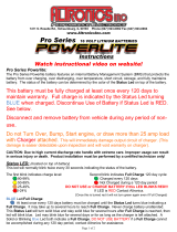
Control Unit:
The Control Unit incorporates a Display, shift control Buttons, and wiring Harness. Display is used to
show gear selection and allows for system and shift point setup. Control buttons allow for manual
gear selection.
2
Actuator:
The actuator mounts to the transmission using the mounting bracket that affixes to the tail shaft
housing using existing housing bolts. Only use specified supplied bracket for brand, type, and model
of transmission. Actuator incorporates a Shift Rod that attaches to transmission shift lever.
SAFE
Button
Display
Control
Unit
Shift
DOWN
Shift UP
Button
Safety Features:
SAFE Button- SAFE Button must be pressed in conjunction with Shift Up or Down button to shift Into
or From Reverse or Park.
Shift Lock - RPM based feature causes system to Lock Out from going from Park to Reverse or
from Neutral to Reverse if the engine rpm is above 2500 (non adjustable). If you try to shift with RPM
to high Display will indicate RPM2HIGH
Reverse Lock Out- RPM based feature causes system to Lock Out from going into Reverse for a set
period (3 seconds) after engine rpm has gone above set point (5000 rpm minimum) even if engine
rpm has gone back under Shift Lock rpm (2500). ). If you try to shift with before lock period has
expired Display will indicate REVLOCK.
Reverse Lock Out protects from accidentally shifting into Reverse after car has crossed finish line
even if user pressed the correct buttons!
Instructional Videos:
There are instructional videos that are highly recommended for viewing for additional information on
the installation and use of your
SHIFT
system. These videos are available on the
www.AltronicsInc.com
web site.

INSTALLATION
System Wiring
System must have a minimum of 12 Volts for optimum performance
3
1) Power to the
SHIFT
must be supplied from the battery of the car. 12 or 16 volt batteries are
compatible. Connect RED wire with in-line (3 amp) fuse to the (+) 12-16 volts directly off of
battery disconnect or isolated power lug. Do not branch from power lug supplying multiple loads.
System must have a minimum of 12 volts for optimum performance.
2) BLACK wire (Ground) should be attached to the (-)Negative Terminal of Battery or common
system chassis ground point.
3) Connect the wire (Tach/Engine Rpm) to the DIGITAL rpm signal output of MSD or
similar ignition system. DO NOT Connect to Ignition Coil. For ignition system without digital RPM
system contact Altronics for proper adapter.
4) Connect the BLUE wire to trans brake (only if shifting on TIME, if shifting on RPM DO NOT
CONNECT.
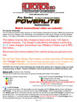
5) Connect the GREEN (Neutral Safety) wire to pin 86 of the relay. Do NOT hook GREEN wire
directly to starter. You MUST use relay!
Starter Neutral Safety relay wiring
Battery
Power
Ground
Control
Unit
Actuator
Actuator
Connector 8 Pin
Engine RPM
/Tach
Neutral
Safety
FUSE
Do not
connect
Trans
Brake
WHITE
Start Solenoid
No Connect
87
87a
30
86
85
Battery
+
Ground
GREEN
wire from
Shift

Mounting Control Unit
Control unit can be mounted on standard 5 bolt pattern steering wheels, dash, console, or any other
location that is driver accessible. When mounting to steering wheel you must provide additional strain
relief to the cables by fastening them with a cable tie or hold down to the wheel.
Dimensions for Mounting holes are 2.69”
Installing shift lever
***
This section must be completed for
SHIFT
system to operate properly***
Shift Lever: Install supplied shift lever. For transmissions with one piece shift lever and rod, the entire
assembly must be replaced. If transmission has two piece lever assembly only the shift lever plate needs to be
changed. See below for you specific transmission type. USE ONLY SUPPLIED SHIFT LEVER PLATE!
Shift Levers
For high mount actuators levers should face up and for low mount face down. Transmission shields
may need to be trimmed to clearance lever when in Park positions (high mount).
Power Glide transmissions: If you transmission has a 1 piece shift lever it must be replaced with a
TCI part #748400 two piece assembly. Only use shift lever supplied by Altronics that came with your
SHIFT
system. Do NOT use the TCI lever plate.
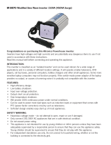
Turbo 350 and 400 transmissions: Shift lever plates are flat but still must have the correct side
facing out. When orientated properly the shift lever will be at the 1 O’clock position when in PARK for
high mount and 7 O’clock for low mount .
Top Mount Bottom Mount
4

Mounting Actuator
Only use supplied bracket for appropriate transmission model. Remove the two bolts from
transmission tail section to hold bracket. If transmission has a shield with a shield bracket on only
one of the mounting hole locations use included washer on other mounting hole to evenly space
bracket from housing. Hold actuator to bracket using the two studs on actuator. Actuator body
temperature should not exceed 150ºF. Check with IR temperature gun.
UNDER NO CIRCUMSTANCES SHOULD YOU MODIFY BRACKET, ACTUATOR, MOUNTING
LOCATION, OR SHIFT RODS! Call Altronics if you have an issue.
Power Glide - Dragster Mount shown below (other types mount in similar manner)
T400 – Bottom Mount (other types mount in similar manner)
Adjusting Actuator Shift Rod
Before connecting actuator shift rod to transmission shift lever, power
SHIFT
ON and put
SHIFT
in NEUTRAL.
Now move transmission shift lever into NEUTRAL. Adjust Rod End length so the stud on Rod End is
lined up with shift lever hole. Once adjusted, check each gear position to verify each is aligned. Now
tighten stud onto lever.
5
Final Check: shift
SHIFT
through each
gear verifying smooth shifts with no binding
or hesitation. You should be able to feel a
slight bit of play in ball joint at each
position. If there is tension at each po
the adjustment is not correct. Loosen lock
nut and turn shift rod shaft to until tension
is gon
sition
e.

6
PROGRAMMING
SHIFT
must be programmed by entering Setup Mode for appropriate transmission type, number
of gears, shift pattern, and shift points.
To enter Setup Mode press both the SAFE and SHIFT UP Buttons at the same time when the
“SHIFT by Altronics” message appears on display just after power up.
Number of Cylinders:
Display will show #Cyl->X Use the UP and Down buttons to select the number of cylinders your
motor has and then press the SAFE button to confirm.
Reverse Lock Out:
Display will show RL->5000 use the UP and Down buttons to select the RPM to enable reverse lock
up and then press the SAFE button to confirm. Minimum RPM is 5000. See Reverse Lock Out
Definition.
Shift Method:
Display will show Select Shift Method->RPM use the UP and Down buttons to select to shift on
RPM or TIME(TIME shift Not available in initial release) and then press the SAFE button to confirm
Select RPM!
Gear Shift Points:
1st Gear:
Display will show 1GS->XXXX use the UP and Down buttons to select RPM value to shift from first to
second gear and then press the SAFE button to confirm.
2nd Gear: (for 3 speed trans)
Display will show 2GS->XXXX use the UP and Down buttons to select RPM value to shift from
second to third gear and then press the SAFE button to confirm.
Continue for additional gears if appropriate.

7
OPERATING
Display will indicate current gear position:
P Park – Park Gear Position
R Revrse – Reverse Gear Position
N Neutrl – Neutral Gear Position
1 First – First Gear Position
2 Second – Second Gear Position
3 Third – Third Gear Position (If applicable)
4 Fourth – Fourth Gear Position (If applicable)
MANUAL OPERTATION
PARK – When in the Park Position you must hold the SAFE Button and Press Shift DOWN Button
together to go into Reverse.
When in Park Position Press Shift UP Button to view Engine RPM, Press Shift DOWN Button to show PARK.
REVERSE - When in the Reverse Gear Position you must hold the SAFE Button and Press Shift UP
or DOWN Button together to go into PARK or NEUTRAL.
NEUTRAL - When in the Neutral Gear Position you must hold the SAFE and Press Shift UP to go
into REVERSE. Press Shift DOWN Button FIRST.
FIRST - When in the First Gear Position Press Shift UP to go into SECOND. Press Shift DOWN
Button NEUTRAL.
SECOND to Final Gear – Use Shift UP or Shift DOWN Buttons to select desired gear.
AUTOMATIC SHIFT OPERATION
*****Verify
SHIFT
is reading correct Engine RPM by putting system in Park Gear Position and
pressing Shift UP Button with engine running, Display will indicate current engine rpm*****
SHIFT
will automatically shift transmission on programmed RPM or TIME(First Gear only) for each
shift First through Final gear position.
SHIFT
can only be manually shifted into NEUTRAL,
REVERSE, and PARK gear positions!
Shift on RPM:
With
SHIFT
in FIRST gear Position, increasing engine rpm above programmed first gear shift point
will cause system to shift into SECOND gear Position.
When in SECOND gear position, again increase engine above programmed second gear shift point
will cause system to shift into THIRD gear Position. This will continue for additional gears if
programmed. (3 or more speed transmissions only!)
Shift on TIME:
If first gear shift point is programmed on TIME, then system will shift from FIRST to SECOND gear
position after programmed amount of time has elapsed from release of transbrake.

TECHNICAL SUPPORT
Email: T[email protected]
When sending a unit in for repair or update: Fill out a “Service Form” which is available from the
Technical Support Section of our website-> www.AltronicsInc.com
WARRANTY
The
SHIFT
by is warranted for 1 Year against any defect in materials and
workmanship from date of purchase. ALL WARRANTIES AND GUARANTEES ARE VOID if the
SHIFT
enclosures are opened or altered or is equipment is connected to system that is not
supplied or authorized by Altronics Inc.
shall not be liable for injury, consequential, or other types of damages resulting
from the use or misuse of the
SHIFT
.
SHIFT
is to be used for off road purposes only!
Error Codes
Error Message Possible Problem Possible Solution
Low Voltage Low Battery Check battery voltage. 12 Volt Minimum
E1 Can’t move into Park Check adjustment shift rod- Check Detent Force
E2 -3 Gear adjustment off Check adjustment shift rod- Check Detent Force
E6 Can’t move into gear position Check adjustment shift rod- Check Detent Force
Email [email protected] with Error Code to resolve error code issues.
8
/