Page is loading ...

34/0
_0!2!$!
34/0
_0!2!$!
4
#ALL5S&IRST
$/./42%452.4/34/2%
&ORIMMEDIATEHELPWITHASSEMBLYORPRODUCTINFORMATION
CALLOURTOLLFREENUMBER
OREMAIL
CUSTOMERSERVICE BACKYARDPRODUCTSLLCCOM
/URSTAFFISREADYTOPROVIDEASSISTANCE
!PRILTHROUGH/CTOBER-&!-TO0-%34
3ATURDAY!-TO0-%34
.OVEMBERTHROUGH-ARCH-&!-TO0-%34
!.4%3$%$%6/,6%2,/_,,«-%./3
3IDESEAMÈSINFORMACIØNSOBREELMONTAJELLÈMENOSSINCOSTE
ADICIONALALGUNOALSIGUIENTETELÏFONO
OCORREOELECTRØNICO
CUSTOMERSERVICE BACKYARDPRODUCTSLLCCOM
.UESTROPERSONALLEPROPORCIONARÈTODALAAYUDAQUENECESITE
!BRILPOROCTUBRE-&%34!A0-%34
ELSÈBADO%34!A0-%34
NOVIEMBREPORMARZO-&%34!A0-%34

4HISPAGEINTENTIONALLYLEFTBLANK
%STAPÈGINAESTÈINTENCIONADOENBLANCO

- BEFORE YOU BEGIN -
Includes 8’x12’ (244x367 cm), 8’x16’ (244x488 cm)
Building Instructions
We manufacture kits from select construction grade lumber and engineered wood products. Construction grade lumber,
a product cut from trees, has many natural characteristics and blemishes that may be present in some of the pieces
you receive in your kit. Natural characteristics and blemishes in construction lumber may include knots, torn wood grain
along edges, minor cracks/splits, twists, limited bark along edges and pitch pockets that may exude sap. Be assured that
the individual parts have been cut and inspected to remove as many of the wood’s natural, less appealing characteristics
as possible. These characteristics and/or blemishes will not affect the strength, durability, or structural integrity of the
nished product. Generally, the exterior trim parts selected for your kit are graded from only one side and should be
installed with the most attractive side outward. Our limited warranty does not cover the natural characteristics and
blemishes that occur with construction grade lumber products.
-
ANTES DE EMPEZAR
-
Tools required
(Herramientas
necesarias)
❑ Hammer
(martillo)
❑ Phillips Screw-
driver
(Desarmador cruz)
❑ Level
(Nivel)
❑ Ladder
(escalera)
❑ Pencil
(lápiz)
❑ Tape Measure
(Cinta métrica)
❑ Utility Knife
(Navaja)
❑ Paint Tools
(Herramientas
para pintar)
❑ Caulk Gun
(pistola para ma-
sillado)
❑ Hand Saw
(Sierra portátil)
❑ Wood Glue
(Pegamento para
madera)
Optional Tools
(Herramientas
opcionales)
❑ Electric Drill w/
#2 Phillips Tip
(Taladro eléctrico
Broca “Phillips”)
❑ Chalk Line
(Linea de marcar)
❑ Square
(Escuadra)
❑ Nail Pouch
(Bolsillo para
clavos)
Fabricamos nuestros equipos de madera elaborada y de productos maquinados de madera
.
La madera elab-
orada, producto de árboles, tiene muchas características e imperfecciones naturales que puedan tener algunas
piezas contenidas en el equipo. Estas imperfecciones y características pueden incluir nudos, grano rasgado
sobre el borde, rajas/grietas pequeñas, torsiones, cortezas en el borde, y bolsos que exuden savia. Asegurams
que hemos cortado e inspeccionado las partes individuales para eliminar las características naturales menos
atractivas posibles. Estas características y/o imperfecciones no afectarán la fuerza, durabilidad ni la integridad
estructural del producto nal. Po lo general, las piezas de moldura exterior seleccionadas para su equipo se
elaboran de un solo lado y deben ser instaladas con la parte más atractiva por fuera. Nuestra garantía limitada
no cubre las características e impefecciones que ocurren con los productos de madera elaborada.
Heritage / Signature Series
Instrucciones para edi cios de
8’x12’ (244x367cm), 8’x16’ (244x488 cm)
8’ Wide Saltbox
Techo a dos aguas 8’
First...
●
Check with your local building authority before erecting.
●
Read instructions thoroughly before you begin.
Building Codes
●
Our buildings are designed to meet most local and national
U.S. codes and are not meant to be used for living space.
●
General construction drawings can be provided.
●
Stamped certi ed drawings can be provided for a fee.
Call for details.
Check All Parts
●
If a part is missing, circle the part in question and call.
●
Please note the primer color may vary on siding and
trim parts. This is a factory applied primer intended for
preparing your building for painting. This is NOT a nish
coat. This primer color variation will not affect the look of
your building once painted.
Important
●
Lumber is graded from one side, use most attractive
face to the outside.
●
In a drawing, a dotted line represents a part hidden from
view (like a part under a panel).
Assistance required
●
Assistance is necessary to handle, t, and secure
some components.
Squareness is very Important!
●
Keep 90° corners and 90° perpendiculars throughout
the assembly to ensure all components t together.
Check foundation size
●
Before starting on your foundation, make sure you are
building the correct size foundation for your building.
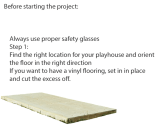
Always wear OSHA-APPROVED safety
glasses throughout assembly process
Primero...
●
Consulte la autoridad de construcción local antes de con-
struir el edi cio.
●
Lea las instrucciones completamente antes de empezar.
Códigos de Construcción
●
Hemos diseñado nuestros edi cios a que conformen con
todos los códigos de construcción locales y nacionales. Los
edi cios no están proyectados como residencia.
●
Se disponen planes generales de construcción.
●
Se disponen de planes certi cados por un precio. Es-
tos planes no garantizan la aprobación de los autoridades
locales.
Compruebe todas las piezas
●
Si falta una pieza, indícala con un círculo y llámenos.
●
Aviso: El color del imprimador puede variar en la covertura
y las partes de la moldura. Este imprimador se aplica en la
fábrica y es para preparar su edi cio para pintar. NO es una
capa de pintura terminada. La variación en el color del impri-
mador no afectará la apariencia de su edi cio al pintarlo.
Importante
●
La Madera está elaborada en un solo lado. Use el lado más
atractivo en el exterior.
●
Si falta una pieza, póngale un círculo y llámenos.
●
En un dibujo una línea punteada representa una pieza no
vista (por ejemplo, una pieza debajo de un panel)
Ayuda requerido
●
Seleccione un sitio nivelado.
●
Será necesario pedir ayuda para manejar, unir, y reforzar
algunas piezas.
¡Es preciso escuadrar el edi cio!
●
Mantenga ángulos de 90° en las esquinas y los perpen-
diculares durante la construcción para asegurar que todas
las piezas se unen correctamente.
Comprueba las dimensiones de la
cimentación.
●
Compruebe que las dimensiones de la cimentación son las
correctas para el edi cio.
Siempre lleve gafas de seguridad aproba-
das por OSHA durante la construcción.
07/22/2011
Shown with extenders
Demostrado con Extensiones
16674-T
Customer Service
(Servico al cliente)
1-888-827-9056
1000 Ternes Drive
Monroe, MI 48162

3
x2
x2
3” (7.6 cm)
2” (5.0 cm)
2” (5.0 cm)
1-1/2” (3.8 cm)
3” (7.6 cm)
2” (5 cm)
1” (2.5 cm)
x 301
x 747
x 238
x 212
x 20
x 12
x 28
HARDWARE
TRIM
TECHO
MURO
3/8”x48”x72”
(.9x122x183 cm)
A
x1
JF
x2
Placa de Union
Q
x4
x2
VF
x4
x4
7/16”x47-7/8”x48”
(1.1x122x122 cm)
J
x2
7/16”x4”x48”
(1.1x10x122 cm)
G
x1
x2
2x4x68”
2x4x48”
UM SP
2” (5.0 cm)
3” (7.6 cm)
2” (5.0 cm)
1-1/2” (3.8 cm)
x 12
x 48
x 56
x 182
Dimensiones VerdaderaActual Size
FERRETER
ÍA
ROOF
WALL
Actual Size
FERRETERÍA
8’ X 12’ (244 x 366 cm)
PARTS LIST
8’ X 12’ (244 x 366 cm)
LISTA DE PIEZAS
8’ X 4’ (244 x 122 cm)
EXTENDER PARTS LIST
8’ X 4’ (244 x 122 cm)
LISTA DE PIEZAS DE EXTENSIÓN
Gusset
HARDWARE
MOLDURA
Rafter
Viga
1x4x60”
Dimensiones Verdadera
(5x10x173 cm)
(5x10x122 cm)
2x6x48”
(5x15x122 cm)
7/16”x23”x48”
(1.1x58x122 cm)
K
x1
Viga
Rafter
x2
QG
QF
(2.5X10X152 cm)
ZT
x2
5/8”x4”x48”
(1,6x10x122 cm)
3/8”x9-3/16”x47-7/8”
(0.95x23x122
cm)
I
x1
x2
x2
1” (2.5cm)
1-1/4” (3cm)
1” (2.5 cm) x 34
1-5/8” (4.1 cm) x 10
C
x2
3/8”x23-7/8”x72”
(.9x61x183 cm)
RS
RS
RS
Aviso
Dos letras o tres letras de identi-
cación están marcadas horizon-
talmente en las piezas. Letras de
identi cación de una sola letra
no están en las piezas.
Note
Double and Triple Letter Part
identi cation letters are stamped
on part and read horizon-
tally, single letter part letters not
stamped on parts.
Nominal Size
(Dimensión nominal)
Lumber Sizes
=
=
=
Dimensiones de la madera
1 x 4
2 x 4
2 x 6
Actual Size
(Dimensiones verdaderas)
3/4” x 3-1/2” (1.9 x 8.9 cm)
1-1/2” x 3-1/2” (3.8 x 8.9 cm)
1-1/2” x 5-1/2” (3.8 x 14 cm)
3/4” (19 mm)
x 43

4
HELPFUL MATERIAL NOTICE
FOR THE BEST LOOKING FINISHED PROD-
UCT WE RECOMMEND THAT YOU INSPECT,
SORT AND LAY OUT MATERIALS PRIOR TO
BEGINNING ASSEMBLY OF YOUR BUILDING
IMPORTANT!!!
Building Tip
IMPORTANTE!!!
Consejo
• Install wall framing with any blemished sides toward the
siding and facing rear of building. (Fig. B)
Always install the material leaving the best edge and best sur-
face visible.
Please remember that these blemishes in no way negatively af-
fect the strength or integrity of our product.
La madera es un producto natural que tiene defectos inherentes.
Todo la estructura interior ha sido aprobada por ofrecer una re-
sistencia estructural y no por su aspecto. La guarnición exterior
ha sido aprobada por tener un buen lado según las normas de la
industria.
Instale siempre el material dejando visibles el mejor borde y la
mejor super cie.
Recuerde que estos defectos no afectan de forma negativa la
resistencia o la integridad de nuestros productos.
B C
A
CON EL FIN DE OBTENER EL PRODUCTO
ACABADO DE MEJOR ASPECTO RECO-
MENDAMOS QUE INSPECCIONE, CLASIFIQUE
Y ORGANICE LOS MATERIALES ANTES DE
EMPEZAR A MONTAR SU EDIFICIO
Wood is a natural product that has inherent blemishes. All interi-
or framing is graded for structural strength and not appearance.
Exterior trim is graded for one good side per industry standards.
• Install corner trim, gable trim and fascia with any blemished
sides toward the siding material. (Fig. C)
AVISO ÚTIL SOBRE LOS MATERIALES
• Blemishes can be easily installed to provide the best
appearance. (Fig. A)
• La parte con defectos puede instalarse fácilmente de modo
que el edi cio tenga el mejor aspecto. (Fig. A)
• Instale la guarnición de las esquinas, la guarnición de
los hastiales y las impostas con los lados con
defectos apuntando hacia el material lateral. (Fig. C)
• Instale el entramado de la pared con los lados con defectos
apuntando hacia los costados y haciendo frente a la parte
trasera del edi cio. (Fig. B)
Please feel free to call our Consumer Help Line - Toll Free
1-888-827-9056
April through October M - F 8:00 AM to 7:00 PM EST
Saturday 8:30 AM to 4:30 PM EST
November through March M - F 8:00 AM to 5:00 PM EST
Llame de forma gratuita a nuestra línea de ayuda al
consumidor
1-888-827-9056
Abril por octubre M - F 8:00 ESTA a 7:00 P.M. EST
el sábado 8:30 ESTA a 4:30 P.M. EST
noviembre por marzo M - F 8:00 ESTA a 5:00 P.M. EST

5
SITE PREPARATION
• Site must be properly leveled.
• Site should have natural drainage
and no standing water
A
B
C
4"
(10 cm)
3-1/2"
(8.9 cm)
A) Purchase our optional Floor Kit or
build your own wood oor.
Building Size
A
8’ x 12’ (244 x 366 cm) 96” (244 cm)
Fasten treated 2x4 sill plates to slab using approved
concrete anchors. (Treated sill plates and fasteners not
included.)
B) Concrete Slab Foundation
FOUNDATION OPTIONS
(Not supplied with kit)
YOU MUST ASSEMBLE YOUR BUILDING ON
A WOOD FLOOR OR CONCRETE SLAB.
OPCIONES PARA LA CIMENTACIÓN
(No incluidas)
HAY QUE CONSTRUIR EL EDIFICIO SOBRE UN
BASE DE MADERA O DE CONCRETO.
PREPARACIÓN DEL SITIO
• El sitio debe de estar nivelado correctamente.
• Instale una barrera contra yerbajos debajo de la
estructura.
Important: Square oor and level to ground
before beginning assembly of building.
Importante: Asegure que el suelo está nivelado y
escuadrado antes de construir el edi cio.
A) Compre nuestro equipo opcional para el
suelo o construya su propio suelo de madera.
B) Base en losa de concreto
AB
144” (366 cm)
96” (244 cm) 192” (488 cm)
8’ x 16’ (244 x 488 cm)
Building Size
8’ x 12’ (244 x 366 cm) 96” (244 cm)
AB
144” (366 cm)
96” (244 cm)
192” (488 cm)
8’ x 16’ (244 x 488 cm)
C
137” (348 cm)
Fije las soleras inferiors tratadas de tamaño 2x4 a la losa
usando anclajes de concreto aprobados. (Las soleras y los
anclajes no están incluidos.)
185” (470 cm)
A
B
Treated Sill
Soleras Inferiors Tratadas
Dimensiones del edi cio
Dimensiones del edi cio

6
8’ X 12’ (244x366 cm)
8’ x 16’ (244x488 cm)
STOP
STOP
Before proceeding, determine
desired door location and
build door wall rst.
Antes de continuar determine la
posición de la puerta y construya
el muro con la puerta primero.
WALL NUMBER EQUALS
PAGE NUMBER
BUILD WALL
NUMBERS SPECIFIED
EL NUMERO DEL MURO CORRESPONDE
AL NUMERO DE LA PAGINA.
CONSTRUYA LOS NÚMEROS DE
LOS MUROS ESPECIFICADOS.
12’ (366cm)
8’ (244cm)
#10
#9
#13
#9
12’ (366cm)
8’ (244cm)
#11
#9
#13
#9
12’ (366cm)
8’ (244cm)
#12
#9
#13
#9
16’ (488cm)
8’ (244cm)
#14
#9
#17
#9
16’ (488cm)
8’ (244cm)
#15
#9
#17
#9
16’ (488cm)
8’ (244cm)
#16
#9
#17
#9

7
Erecting the Walls
Construyendo los Muros
YOUR BUILDING CAN BE CONFIGURED IN A
VARIETY OF WAYS. BEFORE ERECTING WALLS,
REFER TO PAGE 5 TO ENSURE YOU BUILT THE
RIGHT WALLS FOR YOUR BUILDING.
IMPORTANT!!!
Building Tip
ES PRECISO ALINEAR LOS PANELES DE LOS MUROS Y
DEL TECHO ANTES DE CLAVARLOS COMPLETAMENTE
PARA ASEGURAR LA ESCUADRA.
Asegure que se construyan los muros como en los
dibujos abajo.
CONSTRUYA EL MURO CON PUERTA PRIMERO.
Make sure all walls are built as shown below.
BUILD DOOR WALL FIRST.
Flush
Nivelado
3-1/2"
(8.9 cm)
3-1/2"
(8.9 cm)
3-1/2"
(8.9 cm)
3-1/2"
(8.9 cm)
24"
(61 cm)
12" (30 cm)
24"
(61 cm)
24"
(61 cm)
1"
(2.5 cm)
3-1/2"
(8.9 cm)
IMPORTANTE!!!
Consejo
2” (5 cm) Nail/Clavo
2” (5 cm) Nail/Clavo
Inside of Wall
Interior del muro

8
Rack for Squareness
Racking a Roof
When building walls, always apply panel at far left rst. Position
panel ush with top of wall frame and nail in upper corners as
shown. Rack wall square by moving lower end of wall panel right or
left until panel is ush with framing along left edge and secure with
one nail in each lower corner. Continue nailing as instructed.
Alineando un techo
Racking a Wall
Alineando un Muro
YOU MAY NEED TO RACK YOUR WALL
PANELS AND ROOF PANELS TO ENSURE
SQUARENESS BEFORE COMPLETELY
NAILING
Position panel ush with outside front edge of rafter and nail in two cor-
ners as shown. Rack panel square by moving opposite end up or down
until panel is ush along peak of rafters and secure with one nail in each
corner. Ensure spacing of center rafters and nail as instructed.
Posicione los paneles nivelados con el borde delantero exterior de la viga y
clave en las dos esquinas como en el dibujo. Alinee escuadra el panel por
mover los extremos opuestos arriba o abajo hasta que el panel esté nivelado a
lo largo del punto más alto de las vigas, y fíjelo con un clavo en cada esquina.
Compruebe el espacio de las vigas centrales y clave como indicado.
IMPORTANT!!!
Building Tip
ES PRECISO ALINEAR LOS PANELES DE LOS
MUROS Y DEL TECHO ANTES DE CLAVARLOS
COMPLETAMENTE PARA ASEGURAR LA ES-
CUADRA.
Flush
Nivelado
Nail
Clavo
Nivele para escuadrar
IMPORTANTE!!!
Consejo
Al construir los muros, siempre je primero el panel hasta la izquierda
extrema. Posicione el panel nivelado con la parte superior de la es-
tructura del muro y clávelo en la esquina superior como en el dibujo.
Alinee nivelado el muro por mover el lado inferior a la derecha o a la
izquierda hasta que el panel esté nivelado con la estructura a lo largo
del borde izquierda. Fije con un clavo en cada esquina inferior.
A
B
Top Corner Should Be Flush
La esquina superior debe
estar nivelado con la es-
tructura
Flush
Nivelado
Flush
Nivelado
Nail
Clavo
Nail
Clavo
Flush with Rafter Peak
Nivelado con la parte más
alta de las vigas.

9
WALL #9
x 92
MURO #9
WALL #9
x 20
MURO #9
24"
(61 cm)
24"
(61 cm)
24"
(61 cm)
20-1/2"
(52 cm)
92-1/2"
(235 cm)
3-1/2" (8.9 cm)
96"
(244 cm)
92-1/2"
(235 cm)
End View
Vista terminal
End View
Vista terminal
24"
(61 cm)
92-1/2"
(235 cm)
71"
(180 cm)
UM x5
24"
(61 cm)
24"
(61 cm)
20-1/2"
(52 cm)
TJ x2
3”(7.6 cm)
2”(5 cm)
A x2
96"
(244 cm)
3-1/2"
(8.9 cm)
1"
(2.5 cm)
6"
(15 cm)
12"
(30 cm)
Top
Parte Superior
See Page 8 For Building Tip!!!
Flush
Nivelado
Flush
Nivelado
Nail Perimeter
Clave el peri-
metro
Nail Inside Panel
Clave dentro del
panel
¡Ver la página 8 para un consejo!!!
Top
Parte Superior

10
WALL #10
x 124
MURO #10
WALL #10
x 28
MURO #10
6"
(15 cm)
144"
(366 cm)
C x2
3-1/2"
(8.9 cm)
1"
(2.5 cm)
B x2
3”(7.6 cm)
2”(5 cm)
See Page 8 For Building Tip!!!
64"
(163 cm)
140-1/2"
(357 cm)
71"
(180 cm)
UM x6
24"
(61 cm)
16"
(41 cm)
16"
(41 cm)
20-1/2"
(52 cm)
TJ x2
SP x2
End View
Vista terminal
End View
Vista terminal
140-1/2"
(357 cm)
144"
(366 cm)
3-1/2"
(8.9 cm)
92-1/2"
(235 cm)
48"
(122 cm)
64"
(163 cm)
20-1/2"
(52 cm)
16"
(41 cm)
24"
(61 cm)
16"
(41 cm)
Flush
Nivelado
Flush
Nivelado
Nail Perimeter
Clave el peri-
metro
¡Ver la página 8 para un consejo!!!
Top
Parte Superior
Top
Parte Superior

11
WALL #11
x 28
MURO #11
64"
(163 cm)
71"
(180 cm)
UM x6
140-1/2"
(357 cm)
24"
(61 cm)
24"
(61 cm)
16"
(41 cm)
TJ x2
12-1/2"
(32 cm)
SP x2
WALL #11
x 124
MURO #11
3”(7.6 cm)
2”(5 cm)
Top
Parte Superior
Top
Parte Superior
See Page 8 For Building Tip!!!
End View
Vista terminal
End View
Vista terminal
Flush
Nivelado
¡Ver la página 8 para un consejo!!!
16"
(41 cm)
64"
(163 cm)
140-1/2"
(357 cm)
24"
(61 cm)
24"
(61 cm)
12-1/2"
(32 cm)
144"
(366 cm)
140-1/2"
(357 cm)
3-1/2"
(8.9 cm)
144"
(366 cm)
6"
(15 cm)
3-1/2"
(8.9 cm)
1"
(2.5 cm)
B
B
C
Nail Perimeter
Clave el peri-
metro
Flush
Nivelado

12
WALL #12
x 28
MURO #12
WALL #12
x 124
MURO #12
3”(7.6 cm)
2”(5 cm)
16"
(41 cm)
64"
(163 cm)
140-1/2"
(357 cm)
24"
(61 cm)
12-1/2"
(32 cm)
24"
(61 cm)
Top
Parte Superior
End View
Vista terminal
End View
Vista terminal
71"
(180 cm)
UM x6
140-1/2"
(357 cm)
24"
(61 cm)
24"
(61 cm)
16"
(41 cm)
TJ x2
SP x2
12-1/2"
(32 cm)
64"
(163 cm)
144"
(366 cm)
6"
(15 cm)
3-1/2"
(8.9 cm)
1"
(2.5 cm)
B
C
B
144"
(366 cm)
140-1/2"
(357 cm)
3-1/2"
(8.9 cm)
Top
Parte Superior
See Page 8 For Building Tip!!!
¡Ver la página 8 para un consejo!!!
Flush
Nivelado
Flush
Nivelado
Nail Perimeter
Clave el peri-
metro

13
WALL #13
x 135
MURO #13
2”(5 cm)
A x3
6"
(15 cm)
12"
(30 cm)
3-1/2"
(8.9 cm)
1"
(2.5 cm)
144"
(366 cm)
See Page 8 For Building Tip!!!
144"
(366 cm)
140-1/2"
(357 cm)
3-1/2"
(8.9 cm)
Top
Parte Superior
Nail Inside Panel
Clave dentro del
panel
End View
Vista terminal
Nail Perimeter
Clave el peri-
metro
Flush
Nivelado
Flush
Nivelado
¡Ver la página 8 para un consejo!!!
Algunas con guraciones
utilizar
á
n 2 paneles “C” aqui.
Some con gurations will
utilize 2 “C” panels here
WALL #13
x 32
MURO #13
3”(7.6 cm)
24"
(61 cm)
24"
(61 cm)
24"
(61 cm)
24"
(61 cm)
24"
(61 cm)
20-1/2"
(52 cm)
92-1/2"
(235 cm)
48"
(122 cm)
End View
Vista terminal
140-1/2"
(357 cm)
TJ x2
71"
(180 cm)
SP x2
UM x7
24"
(61 cm)
24"
(61 cm)
20-1/2"
(52 cm)
24"
(61 cm)
24"
(61 cm)
24"
(61 cm)
Top
Parte Superior
In some cases this wall will use
2-24” and 2-48” panels, in the fol-
lowing order 24-24-48-48
Esta pared puede utilizar 2-61cm
y 2-122cm paneles, en osta orden
61-61-122-122

14
WALL #14
x 40
MURO #14
188-1/2"
(479 cm)
71"
(180 cm)
UM x8
24"
(61 cm)
24"
(61 cm)
16"
(41 cm)
16"
(41 cm)
24"
(61 cm)
20-1/2"
(52 cm)
64"
(163 cm)
SP x2
SP x2
TJ x2
WALL #14
x 188
MURO #14
3”(7.6 cm)
2”(5 cm)
188-1/2"
(479 cm)
24"
(61 cm)
24"
(61 cm)
16"
(41 cm)
64"
(163 cm)
16"
(41 cm)
24"
(61 cm)
20-1/2"
(52 cm)
Top
Parte Superior
End View
Vista terminal
End View
Vista terminal
B x4
192"
(488 cm)
C
C
B
6"
(15 cm)
3-1/2"
(8.9 cm)
1"
(2.5 cm)
188-1/2"
(479 cm)
192"
(488 cm)
3-1/2"
(8.9 cm)
Top
Parte Superior
See Page 8 For Building Tip!!!
¡Ver la página 8 para un consejo!!!
Nail Perimeter
Clave el peri-
metro
Flush
Nivelado
Flush
Nivelado

15
WALL #15
x 40
MURO #15
WALL #15
x 188
MURO #15
3”(7.6 cm)
2”(5 cm)
188-1/2"
(479 cm)
16"
(41 cm)
12-1/2"
(32 cm)
64"
(163 cm)
24"
(61 cm)
24"
(61 cm)
24"
(61 cm)
24"
(61 cm)
Top
Parte Superior
End View
Vista terminal
End View
Vista terminal
SP x2
SP x2
UM x8
188-1/2"
(479 cm)
12-1/2"
(32 cm)
71"
(180 cm)
64"
(163 cm)
16"
(41 cm)
24"
(61 cm)
24"
(61 cm)
24"
(61 cm)
24"
(61 cm)
TJ x2
192"
(488 cm)
6"
(15 cm)
3-1/2"
(8,9 cm)
1"
(2.5 cm)
C
B
C
C
B
188-1/2"
(479 cm)
192"
(488 cm)
3-1/2"
(8.9 cm)
See Page 8 For Building Tip!!!
Top
Parte Superior
¡Ver la página 8 para un consejo!!!
Flush
Nivelado
Flush
Nivelado
Nail Perimeter
Clave el peri-
metro

16
WALL #16
x 42
MURO #16
WALL #16
x 188
MURO #16
3”(7.6 cm)
2”(5 cm)
End View
Vista terminal
188-1/2"
(479 cm)
192"
(488 cm)
3-1/2"
(8.9 cm)
188-1/2"
(479 cm)
TJ x2
SP x2
SP x2
UM x8
64"
(163 cm)
12-1/2"
(32 cm)
24"
(61 cm)
24"
(61 cm)
24"
(61 cm)
24"
(61 cm)
16"
(41 cm)
71"
(180 cm)
192"
(488 cm)
6"
(15 cm)
3-1/2"
(8.9 cm)
1"
(2.5 cm)
B
B
C
C
C
C
Top
Parte Superior
End View
Vista terminal
188-1/2"
(479 cm)
64"
(163 cm)
24"
(61 cm)
16"
(61 cm)
24"
(61 cm)
12-1/2"
(32 cm)
24"
(61 cm)
24"
(61 cm)
See Page 8 For Building Tip!!!
Top
Parte Superior
¡Ver la página 8 para un consejo!!!
Flush
Nivelado
Flush
Nivelado
Nail Perimeter
Clave el peri-
metro

17
WALL #17
x 44
MURO #17
188-1/2"
(479 cm)
TJ x2
71"
(180 cm)
SP x2
SP x2
UM x9
24"
(61 cm)
24"
(61 cm)
24"
(61 cm)
24"
(61 cm)
24"
(61 cm)
24"
(61 cm)
24"
(61 cm)
20-1/2"
(52 cm)
WALL #17
x 180
MURO #17
3”(7.6 cm)
2”(5 cm)
192"
(488 cm)
A x4
6"
(15 cm)
12"
(30 cm)
3-1/2"
(8.9 cm)
1"
(2.5 cm)
192"
(488 cm)
188-1/2"
(479 cm)
3-1/2"
(8.9 cm)
188-1/2"
(479 cm)
24"
(61 cm)
24"
(61 cm)
24"
(61 cm)
24"
(61 cm)
24"
(61 cm)
24"
(61 cm)
24"
(61 cm)
20-1/2"
(52 cm)
Top
Parte Superior
Top
Parte Superior
See Page 8 For Building Tip!!!
¡Ver la página 8 para un consejo!!!
End View
Vista terminal
Flush
Nivelado
Nail Perimeter
Clave el peri-
metro
Flush
Nivelado
Nail Inside Panel
Clave dentro del
panel
End View
Vista terminal
Algunas con guraciones
utilizar
á
n 2 paneles “C” aqui.
Some con gurations will
utilize 2 “C” panels here

18
ERECTING
WALLS
CONSTRUYENDO
LOS MUROS
3” (7.6 cm) x 17
x 13 (8’x12’) (244 x 366 cm)
x 17 (8’x16’) (244 x 488 cm)
x 10 (8’x12’) (244 x 366 cm)
x 14 (8’x16’) (244 x 488 cm)
3”(7.6 cm)
2”(5 cm)
CONSTRUYENDO
LOS MUROS
See Page 7 for Building Tip!!!
2"
(5 cm)
12"
(30 cm)
3"
(7.6 cm)
3"
(7.6 cm)
3"
(7.6 cm)
3"
(7.6 cm)
3"
(7.6 cm)
12" (30 cm)
12" (30 cm)
2"
(5 cm)
3-1/2"
(8.9 cm)
2"
(5 cm)
2” (5 cm) x 18
Wall/Muro #11
ERECTING
WALLS
See Page 7 for Building Tip!!!
¡Ver la página 7 para un consejo!
¡Ver la página 7 para un consejo!
3"
(7.6 cm)
3"
(7.6 cm)
3"
(7.6 cm)
3"
(7.6 cm)
3"
(7.6 cm)
12"
(30 cm)
2"
(5 cm)
2"
(5 cm)
2"
(5 cm)
KB
ERECT SOLID WALLS FIRST
CONSTRUYA LOS MUROS SÓLIDOS PRIMERO
Level Wall and Brace, Do not
sink nails completely.
Nivele la pared y refuérzala.
No hinque los clavos completa-
mente.
Level Wall and Nail
Nivele la pared y clave
See Page 6 for wall #
Ver la página 6 para # muro.
See Page 6 for wall #
Ver la página 6 para # muro.

19
2” (5 cm) x 20
3” (7.6 cm) x 20
ERECTING
WALLS
CONSTRUYENDO
LOS MUROS
x 18 (8’x12’) (244 x 366 cm)
x 22 (8’x16’) (244 x 488 cm)
x 17 (8’x12’) (244 x 366 cm)
x 21 (8’x16’) (244 x 488 cm)
3”(7.6 cm)
2”(5 cm)
After walls are erected, make sure X to X
and Y to Y measurements are the same
See Page 7 for Building Tip!!! ¡Ver la página 7 para un consejo!
ERECTING
WALLS
CONSTRUYENDO
LOS MUROS
3"
(7.6 cm)
12" (30 cm)
2"
(5 cm)
12"
(30 cm)
2"
(5 cm)
See Page 6 for wall #
Ver la página 6 para # muro
Nivele la pared y clave
Level Wall and Nail
Remove
Quite
3"
(7.6 cm)
12" (30 cm)
3"
(7.6 cm)
12" (30 cm)
2"
(5 cm)
12" (30 cm)
2"
(5 cm)
2"
(5 cm)
12" (30 cm)
Después de construir los muros, asegúrese que
las medidas “X a X” y “Y a Y” son iguales.
Y
X
No clave en la abertura de la puerta.
Do Not Nail In Door Opening
Y
X
See Page 6 for wall #
Ver la página 6 para # muro.
/