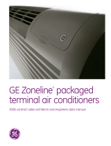
AZ45

GE AZ45 User manual

  • Hello! I am an AI chatbot trained to assist you with the GE AZ45 User manual. I’ve already reviewed the document and can help you find the information you need or explain it in simple terms. Just ask your questions, and providing more details will help me assist you more effectively!
Installing E-Smart W960 Thermostat
GE Zoneline® AZ45 & AZ65 Series
PTAC or Heat Pump
©2023 VTech Communications, Inc. All rights reserved.
Search the Google Play store for the “VTech EC Tool” app or scan the QR code below to access
the app and installation documents on the VTech site. Download and install the app (.apk
le) on your Android smartphone or tablet.
Open the EC Tool app, tap menu > proles, then follow the prompts for creating a customized
prole for your PTAC or Heat Pump. This prole will be used later to provision your
thermostats.
Note: You must create separate proles for Conventional PTACs vs Heat Pumps for the unit
to function properly.
Be sure to have a USB-C to USB-C cable as you will need to connect your smart device to the
USB-C input terminal on the thermostat for provisioning.
Verify the unit is functioning properly using the face
controls prior to installing the thermostat. Power
down the PTAC and remove the cover.
1
Locate the Thermostat Wiring Connector that was
shipped with your Zoneline unit. This is typically
located in the basepan area just below the control
box.
2
Using wire-nuts, attach the supplied VTech Wiring Harness to the corresponding wires to the Zoneline Thermostat
Wiring harness.
3
BEFORE YOU BEGIN
LET’S GET STARTED
VTech to Zoneline Harness Connection
VTech Controller Wire Harness GE Zoneline Wire Harness
Red (24VAC) Red—R—24VAC
Black (Common) Black—C—Common
Purple (Fan Low) Tan—GL—Fan Low
Green (Fan High) Green—GH—Fan High
White (Aux Heat) White—W—Aux Heat
Orange (4-Way/Rev) Blue—B—Reverse Valve
Yellow (Compressor) Yellow—Y—Compressor
Brown (Occ Out) N/A
Once the wiring harnesses are connected, plug the
Zoneline harness connector into the connector
socket on the Zoneline unit. This socket is located
just to the right of the red Aux Set button.
4
Plug the VTech Wiring Harness into the Controller module and press the connector rmly to ensure it snaps into
place. Restore power to the PTAC/PTHP.
5
With the unit connected to power but in OFF mode, update the Auxiliary Control menu to enable “Wired
Thermostat” functionality:
1. Press the red Aux Set button.
2. Using the face controls, press Mode button until the rst digit in the display shows MODE 6 (Remote
Thermostat).
3. Using the face controls, press the Up arrow to turn this option ON, then press again to select 6A (Auto
changeover thermostat).
4. Press the red Aux Set button again to save the setting and exit the conguration mode.
6
Now that the VTech Controller is wired to the Amana unit and it is congured to be controlled by a wired
thermostat, install the batteries into the thermostat. The LED on the controller will change from alternating Green/
Red, to solid green to indicate it has established communication.
7
IMPORTANT NOTE
The W960 thermostat comes preregistered to the controller.
Be sure not to mix the units when removing them from the
packaging. Additionally, avoid pressing the pairing button on
the controller as this can delete the registration requiring you
to re-pair the thermostat and controller.
Prepare the thermostat for conguration:
1. Tap Menu icon to wake the thermostat.
2. Use Menu and up/down to select:
System Settings > System Conguration > Adv Cong via App > Plug cable for setup
3. Plug the USB-C cable into the thermostat.
8
Using the App, provision the thermostat:
9
Tap installation to begin Select a stored prole Assign room number (optional)
Once setup is completed, remove
the cable and the thermostat will
reboot.
Verify security pin
Conrm wiring diagram Tap start to begin
Test your system-Tap any key to wake, then use
UP/DOWN arrows to adjust the target temperature.
Verify heat rst, then cool.
Note: Short-cycle protection will prevent the
compressor from activating for ~3 minutes after
power up.
Mount the controller to the Zoneline chassis and
secure the wiring. Cover/protect unused wire
leads. Route the wires so they do not sag into the
condensation pan. Finally, replace the cover to the
unit.
10 11
Use the included mounting hardware to mount the thermostat wall plate to the wall, then secure the thermostat
to the wall plate using the security screw. The installation is complete.
12
/