Dynojet PC6-17046 Installation guide

Type
Installation guide

Dynojet PC6-17046 gives you the power to transform your 2013-2017 Kawasaki EX300, with features like on-the-fly map switching, gear-dependent tuning, and quick-shifter support. Tap into your bike's sensors to adjust fuel curves based on engine temp or speed, and set RPM limits for controlled launches. Installation is a breeze with the included instructions and color-coded wiring harness. Unleash the full potential of your EX300 with Dynojet PC6-17046.

Dynojet PC6-17046 gives you the power to transform your 2013-2017 Kawasaki EX300, with features like on-the-fly map switching, gear-dependent tuning, and quick-shifter support. Tap into your bike's sensors to adjust fuel curves based on engine temp or speed, and set RPM limits for controlled launches. Installation is a breeze with the included instructions and color-coded wiring harness. Unleash the full potential of your EX300 with Dynojet PC6-17046.

POWER COMMANDER 6
1 POWER COMMANDER 6
1 INSTALLATION GUIDE
1 USB CABLE
2 DYNOJET DECALS
2 POWER COMMANDER DECALS
2 VELCRO STRIPS
1 ALCOHOL SWAB
PARTS LIST
PC6-17046.01
PLEASE READ ALL DIRECTIONS BEFORE STARTING INSTALLATION.
THE IGNITION MUST BE TURNED OFF BEFORE INSTALLATION.
Install guide for: PC6-17046
Model coverage: 2013-2017 Kawasaki EX300
2 13-17 Kawasaki EX300 INSTALLATION GUIDE
Map (Input 1 or 2) The PC6 has the ability to hold 2 different base maps. You can switch on the fly between these two
base maps when you hook up a switch to the MAP inputs. You can use any open/close type switch. The polarity of
the wires is not important.
Shifter (Input 1 or 2) Used for clutch-less full throttle upshifts. Insert the wires from the Dynojet quick shifter into either
Input 1 or Input 2. The polarity of the wires is not important. Set to Input 2 by default.
Speed If your application has a speed sensor then you can tap into the signal side of the sensor and run a wire into this
input. This will allow you to calculate gear position in the Control Center Software. Once gear position is setup
you can alter your map based on gear position and setup gear dependent kill times when using a quickshifter. .
Analog This input is for a 0-5v signal such as engine temp, boost, etc. Once this input is established you can alter your
fuel curve based on this input in the Power Core software.
Launch You can connect a wire to either Input 1 or Input 2 and then the other end to a switch. This switch when engaged
(continuity) will only allow the RPM to be raised to a certain limit (set in the software). When released, you will
have full RPM.
OPTIONAL ACCESSORY INPUTS
WIRE CONNECTIONS
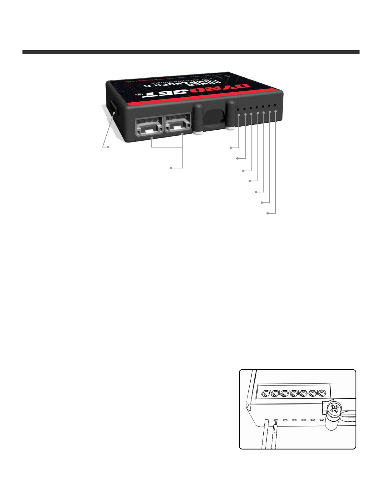
To input wires into the PC6 first remove the rubber plug on the backside of
the unit and loosen the screw for the corresponding input. Using a 22-24
gauge wire, strip about 10mm from its end. Push the wire into the hole of
the PC6 until it stops and then tighten the screw. Make sure to reinstall
the rubber plug.
NOTE: If you tin the wires with solder it will make inserting them easier.
INPUT ACCESSORY GUIDE
SPEED
INPUT 2
INPUT 1
EXPANSION
PORTS 1 & 2
USB
CONNECTION
CRANK
ANALOG
INPUT 2
INPUT 1
PC6-17046
INSTALLING THE POWER COMMANDER 6
1 Remove the seats.
2 Remove the fuel tank.
3 Remove the right and left side mid-fairings.
4 Lay the PC6 in the tail section and route the harness
towards the front of the bike, following alongside
the right side frame rail as closely as possible.
Cross-member brackets may need to be loosened or
removed to route the wiring harness beneath them.
5 Move the junction box out of the way and remove the
bolt for the battery cover.
6 Secure the ground wire of the PC6 wiring harness
with the 6mm ring lug to the negative terminal of the
bike’s battery.
7 Reinstall the battery cover and junction box.
8 Unplug the stock wiring harness from both fuel
injectors.
9 Plug the PC6 wiring harness in-line of the stock
wiring harness and the fuel injectors (Fig. C).
The pair of PC6 connectors with ORANGE colored
wires go to the left-most cylinder (cylinder #1).
The pair of PC6 connectors with YELLOW colored
wires go to the right-most cylinder (cylinder #2).
CONNECT TO INJECTORS
ATTACH GROUND
UNPLUG INJECTORS
4 13-17 Kawasaki EX300 INSTALLATION GUIDE
10 Locate the Throttle Position Sensor on the right
hand side of the throttle bodies.
This is the GREY 3-pin connector.
This picture was taken with the coolant bottle moved
out of the way.
11 Plug the connectors from the PC6 wiring harness in-
line of the TPS and the stock wiring harness.
Make sure you do NOT plug the PC6 in-line of the stock
BLACK connector.
12 Locate and unplug the Crank Position Sensor from
the stock wiring harness.
This is a BLACK 2-pin connector inside of a rubber boot
on the left hand side of the engine head.
INSTALLING THE POWER COMMANDER 6
UNPLUG TPS
CONNECT TO TPS
UNPLUG CPS
STK
PC6
PC6
PC6-17046
13 Plug the PC6 in-line of the stock wiring harness and
the Crank Position Sensor.
14 Unplug the stock wiring harness from the left
ignition coil stick (coil stick #1).
The coil sticks are located directly on top of the
engine’s valve cover.
UNPLUG IGNITION COILS
UNPLUG #1 COIL
INSTALLING THE POWER COMMANDER 6
15 Plug the PC6 wiring harness leads with GREEN
colored wires in-line of the stock wiring harness and
the left ignition coil stick (coil stick #1).
CONNECT TO COIL
6 13-17 Kawasaki EX300 INSTALLATION GUIDE
16 Unplug the stock wiring harness from the right
ignition coil stick (coil stick #2).
17 Plug the PC6 wiring harness leads with BLUE
colored wires in-line of the stock wiring harness and
the right ignition coil stick (coil stick #2) .
18 Using the supplied Velcro secure the PC6 unit in the
tail section.
Be sure to clean both surfaces with the supplied
alcohol swab prior to applying the Velcro.
19 Reinstall the fuel tank, bodywork, and seats.
20 Affix the supplied CARB E.O. label to a conspicuous
area. The best location is next to the original
emissions label. Make sure to clean the surface
before attaching the label.
Optional inputs:
Speed - GREEN/RED wire (pin #5) of the large ECU
connector
Engine Temperature - ORANGE wire (pin #17) of the
large ECU connector
INSTALLING THE POWER COMMANDER 6
UNPLUG #2 COIL
CONNECT TO TPS
UNPLUG CPS
© 2007-2020 DYNOJET RESEARCH ALL RIGHTS RESERVED
2191 MENDENHALL DRIVE, NORTH LAS VEGAS, NV 89081 - 800-992-4993 - DYNOJET.COM
  • Page 1 1
  • Page 2 2
  • Page 3 3
  • Page 4 4
  • Page 5 5
  • Page 6 6
  • Page 7 7

Dynojet PC6-17046 Installation guide

Type
Installation guide

Dynojet PC6-17046 gives you the power to transform your 2013-2017 Kawasaki EX300, with features like on-the-fly map switching, gear-dependent tuning, and quick-shifter support. Tap into your bike's sensors to adjust fuel curves based on engine temp or speed, and set RPM limits for controlled launches. Installation is a breeze with the included instructions and color-coded wiring harness. Unleash the full potential of your EX300 with Dynojet PC6-17046.

Ask a question and I''ll find the answer in the document

Finding information in a document is now easier with AI