Page is loading ...

1
System 5 Digital Audio Mixing System - InDepth

System 5 Digital Audio Mixing System - InDepth
2
Copyright © 2007 Euphonix Inc. All rights reserved. MC, System 5, System 5-MC, S-5, PatchNet, eMix, EuCon, StudioHub, GainBall, SnapShot, SnapShot Recall
are trademarks of Euphonix Inc. Other products mentioned are the trademarks of their respective manufacturers.
Specifications are subject to change without notice.
Euphonix Inc., 220 Portage Ave., Palo Alto, CA 94306, USA. ph: (650) 855 0400 fax: (650) 855 0410
System 5 InDepth
Version 12
All system specifications are subject to change without notice
euphonix.com
Table of Contents
System 5 ........................................................................................................................... 4
System 5 Key Features .................................................................................................... 4
Innovative Solutions ........................................................................................................ 4
System Components ....................................................................................................... 5
The Control Modules ....................................................................................................... 6
Typical Equipment Rack ................................................................................................. 6
System 5 Control Surface - 6 Module Frame ............................................................... 7
Channels .......................................................................................................................... 8
Strips .................................................................................................................................. 9
Inputs .............................................................................................................................. 11
Channel Process Order ................................................................................................ 12
EQ & Filters ..................................................................................................................... 12
Dynamics ....................................................................................................................... 13
Bus Routing and Aux Sends .......................................................................................... 14
Pan Controls .................................................................................................................. 15
Meters ............................................................................................................................ 16
Master Facilities ............................................................................................................. 17
Multi-Operator Systems ................................................................................................ 23
Film Post-Production Monitoring Panel ...................................................................... 24
System 5 Multi-Operator Conguration ..................................................................... 25
SnapShot Recall™ ......................................................................................................... 26
Total Automation™ ...................................................................................................... 26
Fader and Knob Automation Modes ......................................................................... 27
Conforming ................................................................................................................... 27
CM403 Joysticks ............................................................................................................ 27
Patching - PatchNet ..................................................................................................... 28
File Management .......................................................................................................... 29
DF66 DSP SuperCore with MADI I/O & Router............................................................ 30
SC263 Studio Computer ............................................................................................... 31
Interfaces to the Analog & Digital Worlds .................................................................. 32
EuCon Hybrid Option .................................................................................................... 34
Digital Factory, Normandy, France............................................................................. 36
EUPHONIX - SYSTEM 5 INDEPTH

3
System 5 Digital Audio Mixing System - InDepth
System 5 Two-Operator Console
Shepperton Studios, U.K.
EUPHONIX - SYSTEM 5 INDEPTH

System 5 Digital Audio Mixing System - InDepth
4
System 5
System 5 is a high performance digital audio mixing system
specifically designed for audio post-production and music ap-
plications. System 5 has been re-engineered to add a host of
new features ..
• New Control Surface
- New touch-sensitive LED color-coded knobs
- New higher-resolution TFT screens
- Faster processors and more memory
- Improved fader resolution around 0dB
• New EuCon Hybrid Option
- Control multiple DAWs from the System 5 Surface
- Save Layouts of DSP and DAW tracks together
System 5 Key Features
• Easy to use and learn—intuitive interface
• Modular surface and I/O design
• Constant visual feedback for the operator
• Highest sound quality
• Star format Ethernet module interconnection resulting in
more secure operation and no communication bottleneck
• Mixer Channel & Bus Size:
- modular up to 300 channels
- each channel has 4 band EQ, dynamics and two filters
- up to 48 mix buses, 48 group buses, 24 aux sends, 72
external inputs
• High-resolution LED meters next to each fader
• 240 SnapShot Recalls of all console settings
• 48 Layouts for different surface configurations
• PatchNet - digital router/patchbay
• Surround panning and monitoring as standard
• Spill function for easy access to multi-format sources
• 8 Knobs & 100mm touch sensitive moving fader per strip
• TFT high-resolution displays at the top of each channel
for metering (up to 5.1), EQ, dynamics & pan graphs and
routing
• Dynamic automation of most parameters to timecode
• Conform to picture
• Comprehensive machine control facilities integrating with
Soundmaster, Colin Broad, Tamura and JSK
• Up to 3-operator configuration
Innovative Solutions
Layouts
Place sources anywhere on the surface and save the positions
as Layouts for fast access to tracks you need the most.
Multi-Format Masters
Control a surround sound source on one fader.
Spill
Spill brings all the elements of Multi-Format Master to the sur-
face for individual adjustment.
With Spill the 5.1 (or any other format)
Multi-Format Master is ‘spilled’ out to
its six discrete elements for individual
control
INTRODUCTION
• New software features
- Aux to faders
- Scene automation
- Dual zone Spill area
- Buses can be controlled from Strips
- Bus processing
• New DSP SuperCore & Studio Computer
- Faster and more powerful
- More channels & buses
- Supports bus processors
- Fewer rack components
- Up to 1,536x1,536 router (24x24 MADI)
• New modular converters including SDI support
EuCon Hybrid Option
The new EuCon Hybrid option lets System 5 control multiple
DAWs simultaneously bringing DAW tracks onto the console
surface for mixing. No other control system or console
comes close to the power and total integration of
Euphonix control surfaces with EuCon.

5
System 5 Digital Audio Mixing System - InDepth
System Components
Control Surface
Much like any audio console the System 5’s surface includes
channel strips and a center section for master facilities. The
surface is modular, making it easy to add extra channel strips
at any time.
Connections to the rack are Cat 5 Ethernet so placement is not
restricted by complex cabling. No audio flows through the con-
trol surface as the audio electronics are housed remotely.
The console surface controls the Euphonix DSP SuperCore
and, with the EuCon Hybrid Option, can control DAW tracks
on multiple external DAWs via the EuCon control protocol over
Ethernet .
New Digital Processing Core
Audio signals are processed in the new modular DSP SuperCore
which includes DSP for channels, MADI I/O and a router
(patchbay). The DSP SuperCore easily handles 24-bit 48kHz or
96kHz audio up to 40-bit floating point processing and is hard-
ware capable of even higher sample rates up to 384kHz.
Audio Interfaces
Audio Interconnections use AES10 MADI (up to 64 channels
of 24-bit digital audio data carried on a single 75ohm coax
cable or fiber). To interface the console to the outside world,
multi-channel digital and analog converters, digital format
converters with sample rate conversion, as well as remote
mic/line input amps, are available. Cabling is simplified be-
cause converters can be placed next to the equipment they
interface to. The modularity means that the balance between
analog and digital I/O can be tailored to the specific needs
of the facility.
eMix
Operations such as system setup, file management, patch-
ing, and diagnostics are managed by a program called eMix
which runs with a screen and keyboard, usually situated next
to the console. PatchNet, a powerful digital patching system
that handles patching for all the console’s inputs and outputs,
replaces a traditional patchbay with a system that can store
and recall every single patch that is made.
System 5 Control Surface
DSP SuperCore
Converters
eMix Software
SYSTEM COMPONENTS

System 5 Digital Audio Mixing System - InDepth
6
The Control Modules
The System 5 surface is modular and can include 6 different
modules (see opposite page) :
• CM401-T Master Control Module (1ft wide, 305mm)
• CM402-T Sub-Master Control Module (1ft wide, 305mm)
• CM403-F/J Film Module (1ft wide, 305mm)
• CM408-T 8-Fader Channel Strip Module (1ft wide, 305mm)
• CM409-F Blank Module (1ft wide, 305mm)
• Producer’s Desk - Flat worksurface with provision for built-in
high-res 23” TFT screen (2ft wide, 610mm)
Producer’s Desk
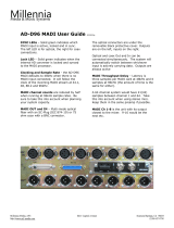
Typical Equipment Rack
The rack below shows a typical System 5 system equipment
rack. Further details about the converters may be found later in
the guide. As the system is modular, additional converters may
be added at any time in the future to allow the system to grow
to match production needs and to match the digital/analog ratio
of sources and destinations.
The typical system shown below has the following I/O
totals:
• 24 Mic Sources
• 26 Analog Line Sources
• 26 Analog Destinations
• 56 Digital Destinations (28 AES/EBU pairs)
• 56 Digital Sources (28 AES/EBU Pairs)
• 4 to 24 MADI I/O (4 per DSP Card)
Frame Height Width Depth
6 modules
39.5” (1 m) 6’10” (2.08m) 41” (1.04m)
9 modules
39.5” (1 m) 9’10” (3m) 41” (1.04m)
12 modules
39.5” (1 m) 12’10” (3.9m) 41” (1.04m)
System 5 Frame
The System 5 Frame comes in three standard sizes.*
* Custom Frame sizes are available.
Two frames are available - the traditional System 5 frame
shown opposite, or a more compact frame this is lighter and
more cost effective.
The main console modules connect to the equipment rack via
Ethernet cables for extremely simple hookup, allowing the sur-
face to be placed long distances from the rack. The CM401-T
Master Control Module also includes talkback wiring.
Ethernet
Switch
MIC LINE INTERFACE
1 2 3 4 5 6 7 8
9 10 11 12 13 14 15 16
17 18 19 20 21 22 23 24
1
9
17
2
10
18
3
11
19
4
12
20
5
13
21
6
14
22
7
15
23
8
16
24 A1 A2 D1 D2
1-8
9-16
17-24
Trim
TRIM
96
48
44.1
CUSTOM
AES
WORD
INTERNAL
AUTO
SR
CONV
1
9
17
2
10
18
3
11
19
4
12
20
5
13
21
6
14
22
7
15
23
8
16
24 A1 A2 D1 D2
1-8
9-16
17-24
Trim
TRIM
96
48
44.1
CUSTOM
AES
WORD
INTERNAL
AUTO
SR
CONV
1
9
17
2
10
18
3
11
19
4
12
20
5
13
21
6
14
22
7
15
23
8
16
24 A1 A2 D1 D2
1-8
9-16
17-24
Trim
TRIM
96
48
44.1
CUSTOM
AES
WORD
INTERNAL
AUTO
SR
CONV
96
48
44.1
CUSTOM
FORMAT CONVERTER
FC
726
WORD
MADI
FORMAT A
AUTO
AES
FORMAT B
FORMAT A
SDIF-2
PRODIGI
TDIF
ADAT
MADI
PROTOOLS
AES
SRC
SDIF-2
PRODIGI
TDIF
ADAT
MADI
PROTOOLS
AES
SRC
SDIF-2
PRODIGI
TDIF
ADAT
MADI
PROTOOLS
AES
SRC
SDIF-2
PRODIGI
TDIF
ADAT
MADI
PROTOOLS
AES
SRC
SDIF-2
PRODIGI
TDIF
ADAT
MADI
PROTOOLS
AES
SRC
SDIF-2
PRODIGI
TDIF
ADAT
MADI
PROTOOLS
AES
SRC
SDIF-2
PRODIGI
TDIF
ADAT
MADI
PROTOOLS
AES
SRC
16
20
24
OUTPUT BIT
DEPTH
16
20
24
16
20
24
OUTPUT BIT
DEPTH
16
20
24
16
20
24
OUTPUT BIT
DEPTH
16
20
24
16
20
24
OUTPUT BIT
DEPTH
16
20
24
16
20
24
OUTPUT BIT
DEPTH
16
20
24
16
20
24
OUTPUT BIT
DEPTH
16
20
24
16
20
24
OUTPUT BIT
DEPTH
16
20
24
SRC ENABLE
ON (STD)
OFF
ON-ALT
MADI
CH 49-56CH 41-48CH 33-40CH 25-32CH 17-24CH 9-16CH 1-8
FC726
Digital I/O
1-56
ML530
Mic Pre
1-24
AM713
ADC
Mic Pre
AM713
ADC
1-26
26 Analog
Out
26 Analog
In
24 Mics
Ethernet
EuCon to
Surface
56 Digital
In and Out
MA703
DAC
1-26
1
9
17
2
10
18
3
11
19
4
12
20
5
13
21
6
14
22
7
15
23
8
16
24 A1 A2 D1 D2
1-8
9-16
17-24
Trim
TRIM
96
48
44.1
CUSTOM
AES
WORD
INTERNAL
AUTO
SR
CONV
MA703
DAC
Monitors
MONITOR-COMMS INTERFACE
MC
524
MC524
Monitor
Controller
MADI
SC263
Studio
Computer
DF66 DSP
SuperCore
Up to 6
SP662 DSP
Cards
Monitors
CONTROL SURFACE

7
System 5 Digital Audio Mixing System - InDepth
Optional CM403-F/J
Film Module with PEC Direct
Panel and Joysticks
CM408-T
8 Fader Channel Strip Module
Color TFT Display
in each module
System 5 Control Surface - 6 Module Frame
CM401-T
Master Control Module
Optional CM402-T
Sub-Master Control Module
CONTROL SURFACE

System 5 Digital Audio Mixing System - InDepth
8
Channels
The number of cards in the DSP SuperCore determine the num-
ber of channels and buses that are available in each System
5. For a given number of cards in the DSP SuperCore, different
combinations of channels and buses may be quickly configured
using the eMix Mixer Model software. Usually a Mixer Model
is chosen during installation and is used throughout the life of
the system as it will best match the application requirements
of the studio.
Each System 5 channel has:
• 2 inputs, that may be fed from analog or digital sources
(using appropriate converters), labelled A & B. Either A, B
or A & B may be selected to feed the channel.
• phase reverse
• gain trim
• delay up to 2 secs
• insert send & return
• 4 band fully parametric EQ
• 2 filters
• dynamics including compress/expand-gate with hyster-
esis, key input and side chain filter
• touch sensitive moving fader
• multi-format panning to mix-minus/group and mix buses
• up to 48 group buses
• up to 24 aux send buses
• solo (APL, PFL, SIP)
• 2 direct outputs - pre-fader & post-fader
If mic preamps are connected to the channel these additional
controls are available which relate to the ML 530 remote mic/
line interface unit :
• input impedance - hi/lo
• phantom power
• hi pass filter
• analog input gain
Function
4 of 7
Function
5 of 7
Function
6 of 7
Function
7 of 7
EQ
Filters
Pre-Fader
Output
Solo
PFL/AFL
Aux
Sends
Grp
Pan/Route
Mix
Pan/Route
S
ystem
Buses
Post-Fader
Direct Output
Fader
& Mute
Any Order
switchable in
pairs of channels
Insert
Function
3 of 7
Function
2 of 7
Delay
DYN
Key
Link
Trim & Phase
Input Select
Channel Inputs
A B
Function
2 of 8
Function
1 of 7
Meter
CHANNELS

9
System 5 Digital Audio Mixing System - InDepth
Strips
System 5 is built up of modules of 8 strips. Controls closely
resemble those of a traditional analog surface. In its simplest
form a single strip controls a single source so a 48 strip surface
could control 48 channels.
TFT Graphic Display:
meters, designation, pan, EQ,
dyn graphs, routing indication
Knobset:
8 knobs with 4 character
displays
Knobset Function Select:
selects the 8 knobs to control
Input, Dyn, EQ, Filters, Aux, Pan
or Routing
Fader:
twin 4-character designations
(that may be linked to the facil-
ity router), solo, channel on,
channel select key for bringing
up the source in the center of
the console, 100mm long-throw
touch-sensitive motorized fader,
twin hi-res LED meters
Swap Button
Designations:
Swap Source
Main Source
ON & Fader
Select/Punch
Wave Button
(brings source
to center)
Touch
Sensitive
Moving Fader
Dual Hi-Res
LED Meters
Swap (Replace)
However there is a very useful function
called “Swap” which allows single strips,
or every strip, to switch between two chan-
nels. So 96 channels (sources) could easily
be controlled from 48 strips by Swapping
between the two layers at the push of a
button (1-48 and 49-96).
System 5 adds further flexibility by allow-
ing any source to be controlled from any
strip, it is even possible to have two strips
controlling a single source. This is where
Layouts come into play.
Layouts & Control Groups
The position of sources on the surface can
be saved and recalled as Layouts. For ex-
ample one Layout could be sources 1-48
and another sources 49-96 for a console
with 96 channels and 48 strips. More im-
portantly the most critical sources can be
placed next to the operator. For example,
dialog to the left and music sources to the
right of the center. Different Layouts can be saved so that the
engineer always has the most important sources within easy
reach. Layouts do not save and recall knob and fader settings,
they simply recall the layout of sources on the control surface.
SnapShots are used to save parameter settings. Control Groups
allow a number of faders to be controlled from a single strip.
Layouts can store/recall the entire desk or only certain strips
defined by the operator.
Central Control of Strips
The Master Control Module includes a complete strip for cen-
tral control of any source. The optional CM402-T module also
includes additional knobsets that are available for control of EQ,
dynamics, aux sends, filters, input and routing at the same time.
Pressing the Wave key next to a source fader brings that source
to the center.
Swaps the Strip between the
Main and Swap Source
STRIPS

System 5 Digital Audio Mixing System - InDepth
10
Bright Orange LED
Pointer
New Rotary Touch Knobs
System 5 uses unique rotary illuminated touch-sensitive knobs
that instantly reset after a recall. The center of the knob also
includes a switch which can be used for certain knobset select
functions, and to punch in the knob automation, if the touch-
sensitive knob automation option is switched off.
The displays reflect the type of control, for example a gain con-
trol is shown opposite. Below are the different displays for dif-
ferent functions:
Knobsets
At the top of each strip are a set of 8 knobs with associated
switches. These knobs can be selected to control the following
parameters using the switches just below the knobs:
• Input Controls
• Dynamics
• EQ & Filters
• Aux Sends - level, pre/post and routing
• Pan
• Routing to Group/Clean Feeds and Mix Buses
The selected button in this photo shows that the knobset is
controlling EQ. To the left of these keys are processor In/Out
switches.
Other Channel Functions
Here are just some extra functions available to the engineer:
• Copy and Paste one strip to another
• Use a single strip to select function such as EQ, Dynamics,
Aux for all strips
• Clear all controls
• Lock a strip to prevent changes when the Layout changes
• Select a strip to be controlled from the center section
• Expand a strip so that EQ, Dyn, etc. controls are spread across
several strips
Strips
Processor In/Out Keys
Knobset Function
Select Keys
Q Pan Gain Frequency
& Q
Knob Status LEDs
Touch - Blue
Auto-Glide - Yellow
Read - Green
Write - Red
Knob Function Color
Input - Red
Expand - Green
Compress - Turquoise
Pan - Dark Blue
Aux - Yellow
EQ & Filters - Violet
Knob with Push
Switch
Switch
Automation
Write
STRIPS

11
System 5 Digital Audio Mixing System - InDepth
Inputs
Each channel has two digital inputs labelled A and B. Controls
for each input include:
• Gain Trim
• Phase Reverse
• Delay
• Input Select (A, B, or A+B)
Patching Input Sources
(PatchNet)
The PatchNet routing system (see page 28) is used to patch
sources to inputs. Any sources within the system, such as mix-
minus/group outputs or externals may be sent to these inputs.
External MADI inputs can also be directly patched. For Analog,
AES/EBU and other digital sources the Euphonix converters are
used. See the Converter section for details (page 32) .
Mic/Line Preamp
For variable gain analog mic in-
puts Euphonix provides the ML
530 with 24 mic/line input pre-
amps and the AM713 analog to
digital converter. If this is con-
nected to the system the controls
for phantom power, input imped-
ance, high pass filter and gain are
available on the channel strip.
This can also act as a direct box,
providing correct impedance
matching with balanced outputs
plus the benefit of gain control.
Impedance
High Z/Low Z
Phantom
In/Out
High Pass Filter
In/Out
Analog Mic/Line Gain
Gain Trim
Phase
In/Out
Delay (up to 2 secs)
In/Out
Input Switch: A, B, A&B
Input Function Selected
B>8A>C:>CI:G;68:
BA
*(%
& ' ( ) * + , -
. &% && &' &( &) &* &+
&, &- &. '% '& '' '( ')
&
.
&,
'
&%
&-
(
&&
&.
)
&'
'%
*
&(
'&
+
&)
''
,
&*
'(
-
&+
') 6& 6' 9& 9'
&"-
."&+
&,"')
Ig^b
IG>B
.+
)-
))#&
8JHIDB
6C6AD<IDB69>
6B
,&(
6:H
LDG9
>CI:GC6A
6JID
HG
8DCK
24 Microphones
ML530 Mic/Line
AM713 Analog to MADI
24 Analog Line Level
MADI to
StudioHub Router
TCC Control
Page to additional controls:
Input A, Input B, Processor In/Out
Analog Controls - ML 530 Mic/Line InterfaceDigital Controls - A Input shown
INPUTS
A Trim
(Digital)
Delay
A Phase
Phantom
Impedance
Hi-Pass
Analog Gain
Chan A In
(Digital)
A/B Select
B Trim
(Digital)
B Phase
Chan B In
(Digital)
A
B
Analog to Digital
Converter

System 5 Digital Audio Mixing System - InDepth
12
Channel Process Order
Each channel has an insert point which can be placed in any of
the seven process positions. The Euphonix converters provide
analog and digital I/O for insertion of any type of device, such
as a delay line, into the signal path.
There are 7 processing sections:
• Delay
• Metering Source
• Insert Point
• EQ
• 2 Filters
• Dynamics
• Fader and Mute
These can be arranged in any order using the eMix application,
even when passing audio, but must be re-ordered at least two
adjacent channels at a time. For example, the EQ may be set to
follow dynamics, the insert may be placed after the EQ or dynam-
ics, and metering, can be placed after the fader, on channels 1
and 2, or on channels 1-8.
EQ & Filters
The EQ controls are shown opposite. Euphonix has a well-
earned reputation for the highest quality EQ algorithms with
an uncompromised approach to design. System 5’s equalizer
is much more than just a simple EQ. The four bands are each
fully parametric, with additionally switchable peak/shelf selec-
tion on two of the bands. Frequencies are not limited to fixed
ranges; each band covers the entire 20Hz - 20kHz spectrum,
with a gain +/- 24dB and local variable Q control. The Page key
at the bottom of the knobs brings up the Filters. There are two
Filters that can each be set to: High Pass, Low Pass, Band Pass
or Notch. Each filter has a frequency control. The notch filter
includes Q control and a “boost/listen” function, monitoring the
audio without the filter in the circuit, to help identify any prob-
lematic frequency prior to selection. A 50/60 Hz hum, or other
unexpected noise problem can be taken care of without disturb-
ing the program mix or compromising any equalizer settings as
with shared designs.
EQ Display
Whenever an equalizer is being adjusted a graphical display ap-
pears to illustrate what the processor is doing to the audio at
the top of the channel.
EQ Select
Clear
High Band
Freq/Q Page
Freq Adj
Peak/Shelf
Gain Adj
High Band In/Out
High Mid Band
Freq/Q Page
Freq Adj
Gain Adj
High Mid Band In/Out
Low Mid Band
Freq/Q Page
Freq Adj
Gain Adj
Low Mid Band In/Out
Low Band
Freq/Q Page
Freq Adj
Peak/Shelf
Gain Adj
Low Band In/Out
Page Keys to Filters
EQ In/Out
EQ Knobset
Select
;jcXi^dc
)d[,
;jcXi^dc
*d[,
;jcXi^dc
+d[,
;jcXi^dc
,d[,
:F
;^aiZgh
;VYZg
BjiZ
6cnDgYZg
hl^iX]VWaZ^c
eV^ghd[X]VccZah
>chZgi
;jcXi^dc
(d[,
;jcXi^dc
'd[,
9ZaVn
9NC
@Zn
A^c`
;jcXi^dc
'd[-
;jcXi^dc
&d[,
BZiZg
EQ

13
System 5 Digital Audio Mixing System - InDepth
Dynamics
The System 5 has an extremely powerful dynamics section
comprising of a Compressor/Limiter, an Expander/Gate and side
chain key input with filter. System 5 allows both Compress and
Expand sections to be used together. The knobset shown op-
posite is the simple Compress/Expand knobset with the main
controls for both sections available. The page keys at the bot-
tom allow the knobset to be switched to a further 3 sets of
knobs that give more advanced control. Here are the full set of
parameters that can be adjusted:
Compressor
Release
Attack
Threshold
Ratio
Depth
Knee
Gain Make Up
Compressor In/Out
Expander/Gate
Release
Attack
Threshold
Ratio
Depth
Knee
Hold
Hysteresis
Expander/Gate In/Out
Side Chain
Filter Type - Hi Pass, Lo Pass, Band Pass, Notch
Side Chain Listen
Side Chain Source - Channel, Key Input, Link
Detector Type - Peak, Average
Dynamics Display
Whenever dynamics are being adjusted a graphical display is
shown on the display at the top of the strip to illustrate how the
processor is affecting the audio.
Dynamics Select
Clear
Compressor
Release
Attack
Threshold
Ratio
Compressor In/Out
Expander
Release
Attack
Threshold
Ratio
Expander In/Out
Page Keys
Dynamics In/Out
Dynamics Knobset Select
DYNAMICS

System 5 Digital Audio Mixing System - InDepth
14
Number of Buses - Mixer Models
The number of Mix, Group and Aux buses available in a Sys-
tem 5 console is dependent on the number of cards in the DSP
SuperCore and the selected Mixer Model. Additional DSP cards
may be added at any time to increase the number of channels.
Bus Processing
The new DSP SuperCore supports dedicated bus processing
comprising filters and dynamics that can be attached to any mix,
group or aux bus and controlled from a Strip.
Mix Buses
The mix buses are grouped in Sections (Stems) to allow mixing
to different formats. For example, a stereo mix section has two
individual buses and a 5.1 mix section has six. Up to 16 mix sec-
tions may be simply configured from the eMix setup software and
each may be given a name. System 5 supports up to 48 individual
mix buses. Formats are Mono, Stereo, LCRS, 5.1, 6.1 and 7.1 plus
custom formats. Routing a source to a Mix Section is done from
the switches on the Knobset after first pressing the Route - Mix
key. Just as with the Aux sends, as shown right, each On/Off key
switches the signal to that bus section. The channel signal may be
routed to all buses in that section with or without the pan inserted.
It is also possible to route to individual buses (direct assign) in each
section, for example, just the center bus of a 5.1 mix section.
Group Buses
Up to 48 audio group/DAW send buses are available. They can
be set to any format from mono thru 7.1. Routing is similar to Mix
buses by pressing the Route - Group key then using the knobset On/
Off switches. For traditional sub-group control these buses may be
brought back into channels that can act as audio sub-group masters
- note that dedicated bus processing is also available. The Group
knobsets also include an overall group send level control.
Aux Send
Up to 24 Aux sends are available and can be configured in mono
or stereo pairs. Press the Aux function key to bring up the Aux
sends on the knobset. The example on the right shows typical
Aux sends with 1 & 2 working as a stereo send with pan. Sends
can be individually set to feed pre or post-fader and can be used
as effects sends or foldback sends. Aux masters are controlled
from the center section and include individual talkback and tone
insert provisions. Each send may be named to reflect its destina-
tion. Aux sends can be flipped to be controlled from the faders
- very useful for setting complex monitor mixes and sends.
Aux Select
Clear
(Aux 1 & 2 are setup as stereo)
Aux 1 & 2 Pan
Pan In/Out
Pre/Post
Aux 1 & 2 Level
Aux 1 & 2 On/Off
Pre/Post
Aux 3 Gain
Aux 3 On/Off
Pre/Post
Aux 3 Gain
Aux 3 On/Off
Pre/Post
Aux 3 Gain
Aux 3 On/Off
Pre/Post
Aux 3 Gain
Aux 3 On/Off
Pre/Post
Aux 3 Gain
Aux 3 On/Off
Pre/Post
Aux 3 Gain
Aux 3 On/Off
Aux Page To Additional Sends
Aux Knobset Select
Group and Mix Routing
Knobset Select
Bus Routing and Aux Sends
BUSES & ROUTING

15
System 5 Digital Audio Mixing System - InDepth
Pan Controls
Pan Formats
Years of experience in the film world allows Euphonix to include
powerful surround features not found on other systems, with
an extremely simple user interface. For surround Mix Sections
(Stems) the following pan controls are available:
• Front Pan
• Surround Pan
• Rear Pan
• Boom Level
• Non-Boom Level
• Divergence
• Focus
• Rotate
Multi-Format Masters and Spill
Stereo sources or surround sources such as a 5.1 pre-mix, or
the 6 sources in an audio sub-group (in the case of 5.1) can
be controlled from a single control strip called a Multi-Format
Master to save on space and to make adjustments, including
routing, much simpler. A function called Spill allows the com-
ponent sources of the Multi-Format Master to be brought up on
the surface, for individual adjustment of each element, at the
push of the channel select button on the Multi-Format Master
or Control Group.
Panning Display
Whenever pan is being adjusted the display above the channel
indicates the pan position.
Pan Select
Clear
Rotate
In/Out
Focus Front
On/Cut
Divergence Front
On/Cut
Non-Boom Level
In/Out (follow front)
Boom Level
In/Out
Pan Rear
In (bypass)/Out (phantom center)
Front/Surround Pan
In/Out (front)
Front Pan
(stereo pan for stereo formats)
In/Out
Page to Extra Pan Controls
Pan Knobset Select
Switch In Pan Controls to
Group and Mix Buses
PAN

System 5 Digital Audio Mixing System - InDepth
16
Meters
The meters above each strip may be set to show any source,
Mix, Group or Aux bus. Single or dual meters can be select-
ed. For example, all strips could have the source fader signal
plus the first 48 strips could also show the mix bus levels.
The example shown to the right has been configured with a
single input meter displaying the source signal (channel 1)
and a dynamics meter.
The meter is accurate to within 1/4dB from 0dBfs down to
48dBfs and displays clip indication. The green bar to the left
of the meter lights showing the approach to peak level.
If the strip is set to a Multi-Format Master that has stereo
or surround format then the meter at the top of the strip will
show stereo or 5.1 metering.
It is also possible to set up the channel meters so that they
display metering for both the Main and Swap sources at the
same time.
Meter Presets
Meter presets allow the setup of meter combinations to
be stored and named for later recall - 24 are available. One
setup could contain primary source meters together with mix
bus signals, another Aux sends.
EQ / Dynamics / Pan Display
Whenever EQ, Dynamics, and Pan are being controlled on the
knobset, a graphical display illustrates what is happening to
the audio.
Channel Routing Display
Source routing to the mix and group buses are also displayed.
The example shown top right is displaying the routing to the
48 group buses, with bus 1 & 2 selected.
High Resolution Meter
Dynamics Meter
Source Designation
Channel Number
EQ Curve
(dynamics & pan curves show
when their knobsets are selected)
Bus Routing Indication
Button Designation
(for the two buttons at top of the strip)
Screen at the top of 8 strips showing 8 channel meters
METERS

17
System 5 Digital Audio Mixing System - InDepth
Master Facilities
Central Assignable Controls
A source can be brought to the center section strip in the CM401-
T Master Module either from one of the strips, by pressing the
Wave key, or by selecting a channel from the 32 keys on the
optional CM402-T Sub-Master module. These 32 keys, together
with source names and ON keys, are located just above the 8
assignable faders and can scroll through all the channels and
control groups on the console. Once a strip has been brought to
the center, control is exactly the same as on a strip elsewhere
on the console. The CM402-T module, as shown below, has 40
extra knobs together with more displays and switches that are
available for expanded EQ, Dynamics, Aux, Input, Group and
Mix bus controls. The screen at the top shows extra metering
and larger graphs for EQ and Dynamics.
8 Assignable Strip Faders
At the bottom of the optional CM402-T are 8 faders. These can
be assigned to control any channel, control group or multi-for-
mat master.
8 Assignable Faders
Central Input, EQ,
Filters, Dynamics,
Aux, Pan, Channel
Controls
Group & Mix Route Buttons
Central Channel Assign Area
Aux / Group / Mix Bus Masters
4 x SLS/Cue Controls
Main Panel
Sub Panel
Solo/AFL/PFL
Main Monitor
Control & Display
Central Assign Strip
Master Fader
Automation Controls
Quick Access Panel
Transport & Locate
32 Channel
Select Keys
with Name
Displays
Optional CM402-T
Sub-Master Module
CM401-T
Master Module
MASTER FACILITIES

System 5 Digital Audio Mixing System - InDepth
18
Master Facilities
CM402-T 32 Source Select Keys
These 32 buttons in the optional CM402-T module make it very
easy to move around the console from the sweet spot. The
display shows the channel name, and the right button beneath
each display selects this channel to the center strip. The left
button can act as an On/Off or a Solo button. The Page keys
at the bottom allow the 32 buttons to page to more channels.
These controls may also be switched to select control groups.
CM402-T Central Knobsets
Aux
Dynamics
Filters
EQ
SUB-MASTER MODULE

19
System 5 Digital Audio Mixing System - InDepth
Master Facilities
Dynamics & EQ
Once a source has been brought to the center, the two sets
of knobs at the bottom of the CM402-T Knobset Panel allow
dedicated control of dynamics (12 left knobs) and EQ (12 right
knobs). Functions are exactly the same as those found in the
strip controls. The CM402-T display includes simultaneous dy-
namics, EQ and filter graphics to show the processor settings.
Upper Knobsets - Aux, Filters & Inputs
At the top of the CM402-T panel are two sets of 8 knobs that can
be switched to control Aux Sends, Filters, and Inputs. The func-
tions available are exactly the same as those found in the strips.
CM402-T 48 Routing Keys
These 48 keys allow group and mix section routing on dedicated
keys.
Bus Masters
Bus Masters are controlled from the 8 knobs and function se-
lect switches in the middle of the console. The knobset can be
switched between Group, Mix and Aux Bus Masters using the
function select keys at the bottom of the knobset. The page key
allows the 8 knobs to switch between sets of 8 controls (1-8,
9-16 etc.)
Each master has a gain trim and On/Off switch plus an insert.
For a Mix Section this will control the gain of all the buses with-
in the section. For the Mix Masters the upper switch next to
each knob switches the knobs to allow On/Off and gain trim for
individual buses within each Section. The user can lock the bus
masters so the point of reference is always the same.
Master Fader
The Master Fader in the middle of the center section controls all
Mix Section output levels. It can also be locked out.
Bus Masters
Bus Designation
Mix Section Expand
Bus Level
On/Off
Page Keys
Bus Master
Knobset
Function Select
SUB-MASTER MODULE & BUS MASTERS

System 5 Digital Audio Mixing System - InDepth
20
Master Facilities
Master Meters
The flat screen display above the center section includes meter-
ing for main monitor outputs. The number of meters will match
the monitor’s format (5.1 is shown in the example below).
The 8 meters at the bottom of the screen are for Aux, Group,
Mix outputs or the SLS/Cue monitors, depending on the bus
master knobset selection.
Solo, AFL, PFL
System 5 includes:
• Solo-In-Place (SIP)
• After Pan Listen (APL)
• Pre Fader Listen (PFL)
• Fader Backstop PFL
• Solo Safe - for isolating effects returns
from Solo-In-Place
The solo control knob in the center section allows the level of
APL and PFL to be set and pressing the top of the knob will clear
any solos. There is also a solo active LED.
Solo Options:
• Inter-cancelling, Momentary or Latching Solo switches
• Solo (AFL, PFL) can be sent to either of the two alternate
speaker outputs or can be sent to whichever is the cur-
rently selected speaker
• Solo can dim the monitors
Monitoring
System 5 has five monitor outputs; Control Room (main and two
alternates), and the SLS/Cue outputs Mon A, B, C and D. Each
of the 5 monitor feeds can select from external inputs config-
ured as External Devices, the Mix Sections (Stems) both bus
and playback return, and the aux sends.
The format of the main control room monitors, and Mon A can
handle up to an 8 output surround format. Even the Alt 1 outputs
can handle 6 speakers which is very useful for a second set of
control room speakers when mixing in surround. Group outputs
are usually monitored on the strips but can also be picked up by
the External inputs using PatchNet.
Monitor Selector
Externals Mix Stems
CR
Monitors
8 Out (max 7.1)
Main
8 Out (max 7.1)
Alt 1
6 Out (max 5.1)
Mon A
8 Out (max 7.1)
Alt 2
Stereo
Mon B
Stereo
Mon C
Stereo
Mon D
Stereo
Aux Sends
Stem
Rtn
Stem
Main Panel
The main panel in the center section is used for making monitor
selections as well as for many other functions including saving
and loading Layouts, Meter Presets and SnapShots. It is very
simple to operate with a straightforward menu structure and
designations which describe functions next to the actual keys.
The External Monitor Selection is shown opposite for selecting
external sources to the Control Room Monitors.
Main Panel
(Currently switched to Solo Options)
4 SLS/Cue
Mon Outs
CR Monitor
Solo
MASTER METERS & MONITORING
/