
1
Before you begin—Read these instructions completely and carefully.
IMPORTANT—Save these instructions for local inspector’s use.
IMPORTANT—OBSERVE ALL GOVERNING CODES AND ORDINANCES.
Note to Installer—Be sure to leave these instructions with the Consumer.
OWNER—Keep these instructions for future reference.
Note—This appliance must be properly grounded.
INSTALLATION INSTRUCTIONS FOR YOUR NEW
30" ELECTRIC COOKTOP
FOR YOUR SAFETY
TOOL LIST
• 1/8" drill bit
• Electric or hand drill
• Flat bladed screwdriver
• Pencil
• Ruler or tape measure and straightedge
• Hand or saber saw
ELECTRICAL REQUIREMENTS
This appliance must be supplied with the proper voltage
and frequency, and connected to an individual, properly
grounded branch circuit, protected by a circuit breaker
or time delay fuse, as noted on rating plate.
Wiring must conform to National Electrical Codes. You
can get a copy of the National Electrical Code, ANSI/
NFPA No. 70-Latest Edition by writing:
National Fire Protection Association
Batterymarch Park
Quincy, MA 02269
We recommend that you have the electrical wiring and
hookup of your counter unit done by a qualified
electrician. After installation, have the electrician show
you where your main disconnect is located.
The range connector block is approved for copper wire
connection only, and if you have aluminum house
wiring, you must use special UL approved connectors
for joining copper to aluminum.
You must use a three-wire, A.C. 208Y/120Volt or 120/
240 Volt, 60 Hertz electrical system. A white (neutral)
wire is not needed for this unit.
Refer to the rating plate on your unit for the K.W. rating
for your counter unit.
SR10239
Pub. No. 31-10147
229C4053P018-4
STOP!
CAUTION:
For Personal Safety remove house
fuse or open circuit breaker before
beginning installation. Failure to do
so could result in serious injury or
even death.
• Be sure your cooktop is installed properly by a
qualified installer or service technician.
• To eliminate the risk of burns or fire by reaching over
heated surface elements, cabinet storage located
above the surface units should be avoided. If
cabinet storage space is to be provided, the risk can
be reduced by installing a range hood that projects
horizontally a minimum of 5" beyond the bottom of
the cabinets. Cabinet installation above the counter
unit may be no deeper than 13".
• The cooktop should be easy to reach and lighted
with natural light during the day.
• Always disconnect the electrical service to the unit
before repairing or servicing the counter unit. This
can be done by disconnecting the fuse or circuit
breaker. Failure to do this could result in a
dangerous or fatal shock. Know where your main
disconnect switch is located. If you don’t know,
have your electrician show you.

2
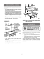
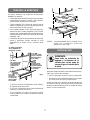
PREPARING THE OPENING
The following MINIMUM clearance dimensions must be
maintained:
• To insure accuracy, it is best to make a template
when cutting the opening in the counter. See Figure
2 for all necessary dimensions.
• Thirty inches (30") minimum vertical clearance from the
cooktop to the nearest unprotected overhead surface.
• One and one half inches (1 1/2") minimum on the right
and two and one half inches (2 1/2") minimum clearance
on the left from counter unit to side wall to a height of
eighteen inches (18").
• Make sure the wall coverings, countertop and cabinets
around the range can withstand heat (up to 200
°
F)
generated by the range, oven or cooktop.
Fig. 1
Fig. 2
2 1/2" MIN.
clearance from
cutout to side
wall on the left
of the unit
30" MIN.
clearance from
countertop to
overhead surface
1 1/2" MIN.
clearance from
cutout to side
wall on the right
of the unit
13" MAX. Depth
of unprotected
overhead cabinets
18" MIN.
height from
countertop to
nearest cabinet on
either side of unit
• (1 3/4") between counter unit rear edge and wall
behind unit.
• (2 1/2") between front edge of counter unit and the
front edge of the counter.
• Five inches (5") minimum vertical clearance between
the cooktop bottom and any combustible surface.
19 3/8"
28 1/2"
20 1/2"
29 1/2"
28 1/2"
*
3 3/8"
1 3/4"
2 1/2" MIN.
19 5/8"
COOKTOP
*NOTE: Depth of the unit at the conduit location
(right rear) is 4 3/4".
INSTALLATION
STOP!
IMPORTANT:
Remove all packing
material and literature from the
cooktop before connecting any
electrical supplies.
Before installing the counter unit or moving it to another
location, have the electrician verify:
• That your home is provided with adequate electrical
service.
• That the addition of the counter unit will not overload
the household circuit on which it is used.
Install an approved junction box where it will be easily
reached through the front of the cabinet where the
counter unit will be located. The counter unit has 3 feet
of conduit.

3
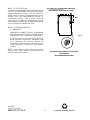
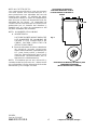
Fig. 3
BE SURE THIS CUT DOES NOT
INTERFERE WITH CABINET
STRUCTURE AT FRONT
16" MIN.
(40.6 CM)
BE SURE THIS CUT DOES NOT INTERFERE
WITH CABINET STRUCTURE AT FRONT
IMPORTANT: The junction box must be located
where it will allow considerable slack in the
conduit for serviceability. See Figure 3.
16" MIN.
SUGGESTED MOUNTING OF AN APPROVED
JUNCTION BOX
(NOT FURNISHED WITH UNIT)
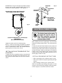
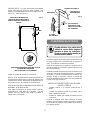
Install the counter unit in the cutout opening.
NOTE: If the unit is being installed in a blind
counter (one with no cabinet opening below),
wire connections must be made before
putting the unit into the cutout.
INSTALLING IN A STANDARD OR TILE
COUNTER:
To attach the unit to a standard counter, insert the hold
down bracket in the slots on each side of the unit. Use
the screws provided to attach the unit to the counter as
shown.
HOLD DOWN
BRACKET
MOUNTING
SLOT
BURNER BOX
SIDES
USE SUITABLE
FASTENERS FOR
ANCHORING IN
CABINET SIDES
CABINET
SIDES
Fig. 4
ELECTRICAL CONNECTIONS
STOP!
The electrical power to the counter
unit supply line must be shut off
while line connections are being
made. Failure to do so could result
in serious injury or death.
When making the wire connections, use the entire
length of conduit provided (3 feet). The conduit must not
be cut.
Connect the red and black leads from the counter unit
conduit to the corresponding leads in the junction box.
The bare ground wire in the conduit is connected to the
counter unit frame. When connecting to a 3-conductor
branch circuit, if local codes permit, connect the bare
ground connector lead of the range to the branch circuit
neutral (gray or white in color).
SPECIAL GROUNDING INSTRUCTIONS
• When connecting to a 4-conductor branch circuit;
• When local codes do not permit grounding through
neutral;
• When installing counter unit in a mobile home:
Attach the appliance grounding lead (green or bare
copper) to the residence grounding conductor (green
or bare copper) in accordance with local codes.

BE SURE THIS CUT DOES NOT
INTERFERE WITH CABINET
STRUCTURE AT FRONT
16" MIN.
(40.6 CM)
— Printed in LaFayette, Georgia —
100% Recycled Paper
Printed LaFayette, Georgia
Recycled Paper
NOTE TO ELECTRICIAN:
The power leads supplied with this appliance
are U.L. recognized for connection to larger
gauge household wiring. The insulation of
these leads is rated at temperatures much
higher than the temperature rating of
household wiring. The current carrying
capacity of a conductor is governed by the
wire gauge and also the temperature rating
of the insulation around the wire.
NOTE: ALUMINUM WIRING
A. WARNING:
IMPROPER CONNECTION OF ALUMINUM
HOUSE WIRING TO THE COPPER LEADS
CAN RESULT IN A SERIOUS PROBLEM.
B. Splice copper wires to aluminum wiring
using special connectors designed and
U.L. approved for joining copper to
aluminum and follow the manufacturer’s
recommended connector procedure
closely.
NOTE: Wire used, location and enclosure of
splices, etc., must conform to good wiring
practice and local codes.
SUGGESTED MOUNTING OF AN APPROVED
JUNCTION BOX
(NOT FURNISHED WITH UNIT)
16" MIN.
Fig. 5
BE SURE THIS CUT DOES NOT INTERFERE
WITH CABINET STRUCTURE AT FRONT
4
SR10239
Pub. No. 31-10147
229C4053P018-4
Page is loading ...
Page is loading ...
Page is loading ...

NOTA AL ELECTRICISTA:
Los conectores eléctricos que se proveen
con esta estufa son reconocidos por U.L.
para conexiones con alambres de casa de
tamaño más grande. El aislante de estos
conectores tienen un valor de temperatura
más alto que el valor de temperatura de los
alambres de las casas. La capacidad de
conducción de corriente de un conductor es
gobernado por el tamaño del alambre y
también por el valor de temperatura del
aislante alrededor del alambre.
BE SURE THIS CUT DOES NOT
INTERFERE WITH CABINET
STRUCTURE AT FRONT
16" MIN.
(40.6 CM)
SUGERENCIA DE MONTAJE DE UNA CAJA DE
CONEXIONES APROBADA
(NO SE PROVEE CON LA UNIDAD)
16" MIN.
Fig. 5
CERCIORESE DE QUE ESTE
CORTE NO INTERFIERA CON LA
ESTRUCTURA DEL GABINETE AL
FRENTE
4
— Impreso en LaFayette, Georgia —
100% Recycled Paper
Printed LaFayette, Georgia
Papel Reciclado
NOTA: ALAMBRES DE ALUMINIO
A. ADVERTENCIA:
LAS CONEXIONES INADECUADAS DE
LOS ALAMBRES DE ALUMINIO DE
LACASA A LOS CONECTORES DE
COBRE PUEDEN RESULTAR EN
SERIOS PROBLEMAS.
B. Conecte alambres de cobre a alambres
de aluminio usando conectores
especiales diseñados y aprobados por
U.L. para juntar cobre y aluminio y
siga los procedimientos para hacer
conexiones recomendados por el
fabricante cuidadosamente.
NOTA: El alambre que se use, ubicación y
cerraduras de las junturas, etc., deben estar
en conformidad con las buenas prácticas de
alambrado y los códigos locales.
SR10239
Pub. No. 31-10147
229C4053P018-4
-
 1
1
-
 2
2
-
 3
3
-
 4
4
-
 5
5
-
 6
6
-
 7
7
-
 8
8


GE Profile JP350AAAA Installation guide
- Type
- Installation guide
- This manual is also suitable for
Ask a question and I''ll find the answer in the document
Finding information in a document is now easier with AI
in other languages
Related papers
Other documents
-
Kenmore 4.2 cu. ft. Self-Clean Drop-In Electric Range - Black Installation guide
-
Frigidaire FFEC3225M User manual
-
Frigidaire FFEC3624PB Installation guide
-
Frigidaire FFED3025PS Installation guide
-
Frigidaire FGIC3067MB Installation guide
-
Kenmore Pro 40403 Installation guide
-
Electrolux E36EC75DSS User manual
-
-
Frigidaire FPIC3077RFA Installation guide
-
Frigidaire FPIC3077RF Installation guide