• When an external power amp is being used with
this system, be sure not to connect the blue/white
lead to the amp’s power terminal. Likewise, do
not connect the blue/white lead to the power ter-
minal of the auto-antenna. Such connection could
cause excessive current drain and malfunction.
• To avoid short-circuiting, cover the disconnected
lead with insulating tape. Especially, insulate the
unused speaker leads without fail. There is a pos-
sibility of short-circuiting if the leads are not
insulated.
• To prevent incorrect connection, the input side of
the IP-BUS connector is blue, and the output side
is black. Connect the connectors of the same col-
ors correctly.
• If this unit is installed in a vehicle that does
not have an ACC (accessory) position on the
ignition switch, the red lead of the unit should
be connected to a terminal coupled with igni-
tion switch ON/OFF operations. If this is not
done, the vehicle battery may be drained when
you are away from the vehicle for several
hours. (Fig. 1)
Fig. 1
• The black lead is ground. Please ground this lead
separately from the ground of high-current prod-
ucts such as power amps.
If you ground the products together and the
ground becomes detached, there is a risk of dam-
age to the products or fire.
• When there is no place surrounding this unit in
which to ground and you wish to extend the black
lead, use a cable with the same or greater thick-
ness (official conductor area of 3.0mm
2
) as the
black lead and connect firmly to a metal portion
of the vehicle. Do not connect the vehicle harness
ISO connector to the black lead.
No ACC positionACC position
O
N
S
T
A
R
T
O
F
F
A
C
C
O
N
S
T
A
R
T
O
F
F
3
ENG/MASTER 96 INST
2
ENGLISH ESPAÑOL DEUTSCH FRANÇAIS
ITALIANO NEDERLANDS
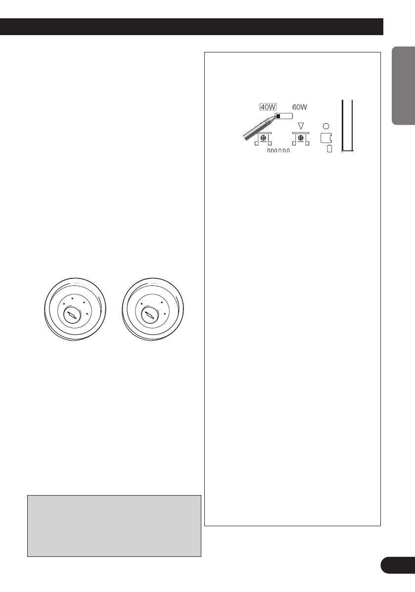
CAUTION:
The default output settings values for this unit are
40W × 4ch. When using this unit at 60W × 4ch you
must adjust the settings switch on the bottom of this
unit. (Fig. 2)
Fig. 2
Follow the below upon connecting with the output set-
tings for this unit set at 60W × 4ch. Connecting with
any other method may result in malfunction.
• Connect the accessory (long red lead) to an acces-
sory circuit of 10A or more when the vehicle
engine switch is set to the ACC position. If the
current is less than 10A the accessory fuse on the
vehicle may be interrupted.
• If this unit is installed in a vehicle that does not
have an ACC (accessory) position on the ignition
switch, install a switch to turn on/off the ACC.
• Connect the battery (yellow lead) to a battery
circuit of 10A or more despite if the vehicle engine
switch is ON or OFF. If the current is less than 10A
the battery fuse on the vehicle may be interrupted.
• If the accessory fuse for the vehicle is less than
10A, use a battery cable such as the RD-221 (sold
separately) for the accessory (long red lead) and
feed the electricity directly from the battery.
• When feeding electricity directly from the battery
for the accessory (long red lead) through a battery
cable, connect the accessory (short red lead) to the
accessory circuit for the vehicle being supplied with
electricity while the vehicle engine switch is set to
the ACC position.
• If the battery fuse for the vehicle is less than 10A,
use a battery cable such as the RD-221 (sold sepa-
rately) for the battery (yellow lead) and feed the
electricity directly from the battery.
• This unit is for vehicles with a 12-volt battery and
negative grounding. Before installing it in a recre-
ational vehicle, truck, or bus, check the battery volt-
age.
• Speakers connected to this unit must be high-power
types with minimum rating of 60 W and impedance
of 4 to 8 ohms. Connecting speakers with output
and/or impedance values other than those noted
here may result in the speakers catching fire, emit-
ting smoke or becoming damaged.
• Cords for this product and those for other prod-
ucts may be different colors even if they have
the same function. When connecting this product
to another product, refer to the supplied manuals
of both products and connect cords that have the
same function.
URD3837A.Eng 04.2.12 4:04 PM Page 3


