Page is loading ...

D
Impressum
Dies ist eine Publikation der Conrad Electronic SE, Klaus-Conrad-Str. 1, D-92240 Hirschau (www.conrad.com).
Alle Rechte einschließlich Übersetzung vorbehalten. Reproduktionen jeder Art, z. B. Fotokopie, Mikroverlmung, oder die
Erfassung in elektronischen Datenverarbeitungsanlagen, bedürfen der schriftlichen Genehmigung des Herausgebers.
Nachdruck, auch auszugsweise, verboten. Die Publikation entspricht dem technischen Stand bei Drucklegung.
© Copyright 2014 by Conrad Electronic SE.
G
Legal Notice
This is a publication by Conrad Electronic SE, Klaus-Conrad-Str. 1, D-92240 Hirschau (www.conrad.com).
All rights including translation reserved. Reproduction by any method, e.g. photocopy, microlming, or the capture in elec-
tronic data processing systems require the prior written approval by the editor. Reprinting, also in part, is prohibited. This
publication represent the technical status at the time of printing.
© Copyright 2014 by Conrad Electronic SE.
F
Information légales
Ceci est une publication de Conrad Electronic SE, Klaus-Conrad-Str. 1, D-92240 Hirschau (www.conrad.com).
Tous droits réservés, y compris de traduction. Toute reproduction, quelle qu‘elle soit (p. ex. photocopie, microlm, saisie
dans des installations de traitement de données) nécessite une autorisation écrite de l‘éditeur. Il est interdit de le réimpri-
mer, même par extraits. Cette publication correspond au niveau technique du moment de la mise sous presse.
© Copyright 2014 by Conrad Electronic SE.
O
Colofon
Dit is een publicatie van Conrad Electronic SE, Klaus-Conrad-Str. 1, D-92240 Hirschau (www.conrad.com).
Alle rechten, vertaling inbegrepen, voorbehouden. Reproducties van welke aard dan ook, bijvoorbeeld fotokopie, micro-
verlming of de registratie in elektronische gegevensverwerkingsapparatuur, vereisen de schriftelijke toestemming van de
uitgever. Nadruk, ook van uittreksels, verboden. De publicatie voldoet aan de technische stand bij het in druk bezorgen.
© Copyright 2014 by Conrad Electronic SE. V8_0614_01/IB

Dear customer,
Thank you for making the excellent decision to purchase this Voltcraft® product.
You have acquired a quality product from a brand family which has distinguished itself in the elds of measuring,
charging and network technology thanks to its particular expertise and its permanent innovation.
The products of the Voltcraft® family offer optimum solutions even for the most demanding applications for ambi-
tious hobby electricians as well as for professional users. Voltcraft® offers you reliable technology at an extraordi-
narily favourable cost-performance ratio.
Therefore, we are absolutely sure: Your starting to use Voltcraft will also be the beginning of a long, successful
relationship.
And now enjoy your new Voltcraft® product!
Tel. no.: +49 9604 / 40 88 80
Fax. no.: +49 9604 / 40 88 48
Mon. to Thur. 8.00am to 4.30pm, Fri. 8.00am to 2.00pm

G
Introduction ................................................................................................................................................................. 27
Intended use .............................................................................................................................................................. 29
Operating elements .................................................................................................................................................... 30
Safety instructions ...................................................................................................................................................... 30
Product description ..................................................................................................................................................... 33
Delivery contents ........................................................................................................................................................ 33
Display indications and symbols ................................................................................................................................. 34
Measuring mode ......................................................................................................................................................... 35
a) Voltage measuring “V” .................................................................................................................................. 35
b) Current measuring “A“ ................................................................................................................................. 36
c) Frequency measuring and duty cycle (only VC170-1) .................................................................................. 37
d) Resistance measuring .................................................................................................................................. 38
e) Diode test ..................................................................................................................................................... 39
f) Continuity check ........................................................................................................................................... 40
g) Non-contact AC voltage-test “NCV” .............................................................................................................. 40
h) Transistor test “hFE” ..................................................................................................................................... 41
i) Temperature measuring (only VC150-1) ...................................................................................................... 41
SELECT button (only VC170-1) .......................................................................................................................... 42
HOLD function .................................................................................................................................................... 42
Optional measuring adapter ............................................................................................................................... 43
Maintenance and cleaning ......................................................................................................................................... 43
General ............................................................................................................................................................... 43
Cleaning .............................................................................................................................................................. 43
Changing the fuse ............................................................................................................................................... 44
Inserting/changing the batteries .......................................................................................................................... 44
Disposal of at batteries ............................................................................................................................................. 45
Disposal ...................................................................................................................................................................... 46
Troubleshooting .......................................................................................................................................................... 46
Technical data ............................................................................................................................................................. 47

- Measuring and displaying electric parameters in the range of excess measuring category CAT III (up to max. 250V
against ground potential, pursuant to EN 61010-1) and all lower categories. The meter must not be used in the
measuring category CAT IV.
- Measuring direct and alternating voltage up to a maximum of 250 V
- Measurement of direct and alternating current up to 10 A (VC130-1/VC150-1 direct current only)
- Frequency measuring 10 Hz up to 10 MHz (only VC170-1)
- Measuring of resistance up to 20 MOhm (VC170-1 up to 40 MOhm)
- Acoustic continuity check
- Diode test
- No-contact 230V/AC voltage test
- hFE transistor test (only with optional measuring adapter)
- Temperature measuring from -40 to +1000°C (only VC150-1)
The two current measuring inputs are secured against overload. The voltage in the measuring circuit may not
exceed 250 V. The measuring ranges are equipped with ceramic high-performance fuses.
The device may only be operated with the specied batteries.
The measuring instrument must not be operated when it is open, i.e. with an open battery compartment or when the
battery compartment cover is missing. Measuring in damp rooms or under unfavourable ambient conditions is not
admissible.
For safety reasons, when measuring only use measuring cables or accessories which are adjusted to the specica-
tions of the multimeter.
Unfavourable ambient conditions are:
- Wetness or high air humidity
- Dust and ammable gases, vapours or solvent,
- Thunderstorms or similar conditions such as strong electrostatic elds etc.
Any use other than the one described above damages the product. Moreover, this involves dangers such as e.g.
short circuit, re, electric shock, etc. No part of the product must be modied or rebuilt!
Read the operating instructions carefully and retain them for later reference.
The safety instructions must be observed at all times.

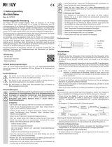
(see fold-out page)
1 No-contact voltage detector
2 LC display
3 POWER button on the VC130-1/150-1
SELECT button on the VC170-1 for
function switching
4 Rotary switch
5 COM measuring socket (reference potential)
6 10 A measuring socket
7 mAµA measuring socket
8 V measuring socket
9 HOLD button
10 Battery compartment
11 Stand clamp
This device left the manufacture’s factory in a safe and perfect condition.
We kindly request that you as a user observe the safety instructions and warnings contained in this operating
manual to preserve this condition and to ensure safe operation!

An exclamation mark in a triangle indicates important notices in these operating instructions which have
to be observed under all circumstances!
The triangle containing a lightning symbol warns of danger of an electric shock or of the impairment of the
electrical safety of the device.
The “arrow” symbol indicates special information and advice on operation of the device.
This product has been CE-tested and meets the necessary European guidelines.
Class 2 insulation (double or reinforced insulation)
CAT II Measuring category II for measurements on electric and electronic devices connected to the mains sup-
ply with a power plug. This category also covers all smaller categories (e.g. CAT I for measuring signal
and control voltages).
CAT III Measuring category III for measuring in building installation (e.g. outlets or sub-distribution). This category
also covers all lower categories (e.g. CAT II for measuring electronic devices). Measuring operation in
CAT III is only permissible with cover caps at the measuring prods.
CAT IV Measuring category IV for measuring at the source of the low-voltage installation (e.g. main distribution,
house-transfer points of energy providers, etc.).
Ground potential
The unauthorised conversion and/or modication of the unit is inadmissible because of safety and approval reasons
(CE).
Consult an expert when in doubt about the operation, the safety or the connection of the device.
Measuring instruments and accessories are not toys and have no place in the hands of children.
On industrial sites the accident prevention regulations of the association of the industrial workers’ society for electri-
cal equipment and utilities must be followed.
In schools, training centres, computer and self-help workshops, handling of measuring instruments must be super-
vised by trained personnel in a responsible manner.
The voltage between the measuring instrument connection points and earth must never exceed 250 V DC/AC in
CAT III.

When using the measuring lines without cover caps, measurements between the
meter and the earth potential must not be performed above the measuring category
CAT II.
When measuring in the measuring category CAT III, the cover caps must be pushed
onto the measuring prods to avoid accidental short circuits during measurement.
Push the cover caps onto the measuring prods until they latch. To remove them, pull
the caps from the prods with a little force.
The test prods have to be removed from the measured object every time the measur-
ing range is changed.
Be especially careful when dealing with voltages higher than 33V AC or 70 V DC. Even at such voltages you can
receive a life-threatening electric shock when you come into contact with electric wires.
Check the measuring device and its measuring lines for damage before each measurement. Never carry out any
measurements if the protecting insulation is defective (torn, ripped off etc.) Measuring cables have a wear indicator.
When they are damaged, a second insulation layer in a different colour becomes visible. The measuring accessories
must no longer be used and must be replaced.
To avoid an electric shock, make sure not to touch the connections/measuring points to be measured neither directly
nor indirectly during measurement. During measuring, do not grip beyond the tangible grip range markings present
on the test prods.
Do not use the multimeter just before, during or just after an electrical storm (electrical shock / high-energy overvolt-
age!). Please make sure that your hands, your shoes, your clothing, the oor, switches and switching components
are dry.
Avoid an operation near:
- strong magnetic or electromagnetic elds
- transmitter aerials or HF generators,
Since this could affect the measurement.
If you have a reason to believe that the device can no longer be operated safely, disconnect it immediately and
secure it against being operated unintentionally. It can be assumed that safe operation is no longer possible if:
- the device is visibly damaged,
- the device does not operate any longer and
- the device was stored under unfavourable conditions for a long period of time or
- it has been subjected to considerable stress in transit.
Do not switch the measuring instrument on immediately after it has been taken from a cold to a warm environment.
The condensation that forms might destroy your device. Leave the device switched off and wait until it has reached
room temperature.
Do not leave the packaging material lying around carelessly since such materials can become dangerous toys in the
hands of children.
You should also heed the safety instructions in each chapter of these instructions.

The multimeter (referred to as DMM in the following) indicates measured values on the digital display. The measur-
ing value display of the DMM spans 2000 counts with VC130-1 and VC150-1 as well as 4000 counts with VC170-1
(count = smallest display value). The VC170-1 sets the right measuring range automatically (AUTO range). How-
ever, manual selection of the measuring range is still possible.
The measuring device can be used for do-it-yourself or for professional applications (up to CAT III 250V).
For better readability, the DMM can also be mounted with the clip on the rear.
The individual measuring functions are selected via a rotary switch. With the VC130-1 and the VC150-1, the meas-
uring range is selected manual, with the VC170-1 automatically (auto range; the right measuring range is always set
here automatically).
The DMM VC130-1 and VC150-1 are turned on and off via the button “POWER”. When the rotary switch is set to
“OFF”, the VC170-1 is turned off. Always turn the measuring device off when it is not in use.
Prior to working with the measuring device, you rst have to insert the enclosed batteries.
Insert the battery as described in the chapter “Cleaning and Maintenance”. A 9V block battery is required for voltage
supply. This is part of the delivery.
The VC170-1 appliance turns off automatically after approx. 15 minutes. Remove the measuring cable from the
measuring object. To reactivate, turn the rotary switch once to the position “OFF” and then select the desired
measuring range again.
Multimeter
9V block battery
Safety measuring lines with plugged-on CAT III cover caps
K-type temperature sensor (-40 to + 230 °C; only with VC150-1)
Operating instructions

AUTO Automatic measuring range selection (only VC170-1)
.OL or I Overload, the measuring range was exceeded
Battery replacement icon; please replace the battery as soon as possible
Symbol for the diode test
Blitz
Lightning icon for voltage measuring
Symbol for the acoustic continuity tester
AC Alternating size for voltage and current
DC Direct magnitude for voltage and current
mV Millivolt (exp.-3)
V Volt (unit of electric potential)
A Ampere (unit of electric current strength)
mA Milli ampere (exp.-3)
µA Microampere (exp.-6)
Hz Hertz (unit of frequency)
kHz Kilohertz (exp.3)
MHz Megahertz (exp.6)
Ω Ohm (unit of electric resistance)
kΩ Kiloohm (exp.3)
MΩ Megaohm (exp.6)
% Display of the pulse/break ratio (duty cycle)
°C Unit of temperature
hFE Display of the amplication factor for transistors
COM Reference potential
H Symbol for active hold function
Delta symbol for active relative measuring function (only VC170-1)
NCV Contact-free alternate voltage recognition

If the measuring range is exceeded, an overload is displayed. This display is model-dependent and signalled
with “I” in the VC 130-1 and VC150-1 and with “OL” in the VC170-1. Select the next-higher measuring range.
The voltage range „V/DC“ has an input resistance of >10 MOhm, the V/AC range of >4.5 MOhm
With the VC170-1, the automatic range selection (auto range) is active in all measuring functions (except for
currency measuring ranges). This function sets the right measuring range automatically.
Before measuring voltages, always make sure that the measuring instrument is not set to a measuring range for
currents.
Measuring socket selection and assignment of the black and red measuring cable
DMM black red
VC130-1 COM (5) V (8)
VC150-1 COM (5) V (8)
VC170-1 COM (5) V (8)
- Turn the DMM on (VC130-1/150-1 on the “POWER” switch (3) and the VC170-1 on the rotary switch). Select the
measuring range “V
”.
- Insert the measuring cables into the corresponding measuring sockets as shown in the table.
- Now connect the two measuring prods to the object to be measured (battery, switch etc.).
The red measuring tip indicates the positive pole, the black measuring tip the negative pole.
- The polarity of the respective measuring value is indicated on the together with the current measuring value.
As soon as a minus “-” appears for the direct voltage in front of the measuring value, the measured voltage is
negative (or the measuring tips have been mixed up).
- After measuring, remove the measuring leads from the measuring object and turn the DMM off. Turn the rotary
switch to the position “OFF” or turn the device off via the “POWER” switch.

- Put the DMM into operation as described in the section “Measuring of direct voltage” and select the measuring
range “V “
“AC” appears on the display.
- Now connect the two measuring prods to the object to be measured (generator, switch etc.).
- The measuring value is indicated on the display
- After measuring, remove the measuring leads from the measuring object and turn the DMM off. Turn the rotary
switch to the position “OFF” or turn the device off via the “POWER” switch.
Measuring socket selection and assignment of the black and red measuring cable
DMM black red
µA,mA A
VC130-1 COM (5) mA (7) A (6)
VC150-1 COM (5) mA (7) A (6)
VC170-1 COM (5) mA (7) A (6)
- Plug the red measuring lead into the 10 A measuring socket (at currents> 200 /> 400 mA depending on the model)
or into the mAµA measuring socket (at currents> 200 /> 400 mA depending on the model). Plug the black measur-
ing lead into the COM socket.
- Select the measuring range Try to start measuring with the largest measuring range if possible, because the ne
fuse will trigger in case of excess current.
- Now connect the two test prods in series with the object to be measured (battery, circuit etc.); the display indicates
the polarity of the measured value together with the currently measured value.
As soon as a minus “-” appears for the direct voltage measuring in front of the measuring value, the meas-
ured voltage is negative (or the measuring tips have been mixed up).
- After measuring, remove the measuring leads from the measuring object and turn the DMM off. Turn the rotary
switch to the position “OFF” or turn the device off via the “POWER” switch.

Alternate current measuring is only possible with the VC170-1!
Select the desired measuring range and press the button “SELECT” (3) to switch to the AC range. “AC” appears on
the display.
Pressing this button again, takes you back etc.
After measuring, remove the measuring leads from the measuring object and turn the DMM off. Turn the rotary
switch to “OFF”.
The VC170-1 can be used to measure and indicate signal voltage frequencies from 10 Hz up to 10 MHz.
Measuring socket selection and assignment of the black and red measuring cable
DMM black red
VC170-1 COM (5) V/Hz (8)
- Turn the DMM on at the rotary switch and select measuring range “Hz/%”.
- Plug the red measuring lead into the Hz measuring socket and the black measuring lead into the COM measuring
socket.
- Now connect the two measuring prods to the object to be measured (signal generator, switch etc.).
- The frequency and corresponding unit are displayed.
- After measuring, remove the measuring leads from the measuring object and turn the DMM off. Turn the rotary
switch to “OFF”.
- Connect the DMM as described for frequency measuring and select the measuring range “Hz/%”.
- Press the button “SELECT”. The pulse/break ratio is displayed in %.
- After measuring, remove the measuring leads from the measuring object and turn the DMM off. Turn the rotary
switch to “OFF”.

Measuring socket selection and assignment of the black and red measuring cable
DMM black red
VC130-1 COM (5) mA/Ω (7)
VC150-1 COM (5) mA/Ω (7)
VC170-1 COM (5) V/Ω (8)
Proceed as follows to measure the resistance:
- Turn the DMM on and select measuring range “Ω”.
- Insert the measuring cables in line with the model into the corresponding measuring sockets as shown in the
table.
- Check the measuring leads for continuity by connecting both measuring prods to one another. After that the resist-
ance value must be approximately 0.5 Ohm (inherent resistance of the measuring leads).
- While the measuring tips are short-circuited, press the button “SELECT” (only with the VC170-1)) to not let the
inherent resistance of the measuring leads ow into the following resistance measuring. The display shows 0 Ohm
- Now connect the measuring prods to the object to be measured. As long as the object to be measured is not high-
resistive or interrupted, the measured value will be indicated on the display. Wait until the display has stabilised.
With resistances of >1 MOhm, this may take a few seconds.
- If “overload” appears on the display, you have exceeded the measuring range or the measuring circuit is inter-
rupted.
- After measuring, remove the measuring leads from the measuring object and turn the DMM off. Turn the rotary
switch to the position “OFF” or turn the device off via the “POWER” switch.
If you carry out a resistance measurement, make sure that the measuring points which you contact with the
measuring prods are free from dirt, oil, solderable lacquer or similar. An incorrect measurement may result
under such circumstances.

Measuring socket selection and assignment of the black and red measuring cable
DMM black red
VC130-1 COM (5) mA/Ω (7)
VC150-1 COM (5) mA/Ω (7)
VC170-1 COM (5) V/Ω (8)
- Turn the DMM on and select measuring range
- Insert the measuring cables in line with the model into the corresponding measuring sockets as shown in the
table.
- Check the measuring leads for continuity by connecting both measuring prods to one another. After that the value
must be approximately 0 V. The open-circuit voltage is approx. 3 V.
- Now connect the two measuring prods with the object to be measu-red (diode).
- The display shows the continuity voltage in volt (V).
- If the symbol for “overload” is shown the diode is measured in the locking direction
or the diode is defective (interruption). Perform a counter-pole measuring for control
reasons. The red measuring lead corresponds to the positive pole (anode), the black
measuring lead to the negative pole (cathode). A silicone diode has an on-state volt-
age of approx. 0.5 – 0.8 V.
- After measuring, remove the measuring leads from the measuring object and turn the DMM off. Turn the rotary
switch to the position “OFF” or turn the device off via the “POWER” switch.

.
Measuring socket selection and assignment of the black and red measuring cable
DMM black red
VC130-1 COM (5) mA/Ω (7)
VC150-1 COM (5) mA/Ω (7)
VC170-1 COM (5) V/Ω (8)
- Turn the DMM on and select measuring range
- Insert the measuring cables in line with the model into the corresponding measuring sockets as shown in the
table.
- To activate the acoustic continuity tester function, press the button “SELECT” (3). Pressing this button again takes
you back to the rst measuring function (diode test) etc.
- A measuring value of approx. < 10 Ohm is detected for the throughput and a permanent signal sounds.
- If “overload” appears on the display, you have exceeded the measuring range or the measuring circuit is inter-
rupted.
- After measuring, remove the measuring leads from the measuring object and turn the DMM off. Turn the rotary
switch to the position “OFF” or turn the device off via the “POWER” switch.
- Turn the DMM on and select measuring range “NCV”
- Test this function beforehand on a known AC voltage source.
- Guide the measuring device with the sensor area (1) towards to position to be tested at a distance of max. 10 mm.
In case of twisted cables, it is recommended to check the cable at a length of approx. 20 to 30 cm.
- An acoustic signal sounds during voltage recognition. The display is not needed for this and shows no dened
values.
- After you nish measuring, turn the DMM off. Turn the rotary switch to the position “OFF” or turn the device off via
the “POWER” switch.
Due to the sensitivity, static elds may also be displayed when touching. This is normal and does not inu-
ence the test result.

- Turn the DMM on and select measuring range “hFE”
- Disconnect all measuring leads from the measuring instrument.
- Attach the optionally available measuring adapter to the three measuring
sockets COM (5) + V (8) + mA (7)
- Insert the transistor to be tested into the corresponding header observing
the correct polarity. The left header is intended for NPN types and the right
header for PNP types. SMD types can also be tested.
- The amplication factor “hFE” is displayed
- After measuring, remove the adapter and turn the DMM off. Turn the rotary
switch to the position “OFF” or turn the device off via the “POWER” switch.
- Turn the DMM on and select measuring range “°C”
- Disconnect all measuring leads from the measuring instrument.
- Connect the enclosed temperature sensor with the DMM. The red plug must be inserted into the socket “°C” (7),
the black plug into the socket “COM” (5).
- Now expose the sensor tip to the temperatures.
- The display shows the temperature on the sensor. If “I” appears, the measuring range was exceeded or there is
no sensor connected.
- After measuring, remove the adapter and turn the DMM off. Turn the rotary switch to the position “OFF” or turn the
device off via the “POWER” switch.
If the two sockets “COM” (5) and “°C” (7) are short-circuited, the ambient temperature of the measuring
device is displayed.
The use of K-type sensors with miniature plugs requires the application of the optional measuring adapter
(see chapter “Optional measuring adapter”).

The SELECT button has several functions depending on the measuring range. For function switching, for a relative
measuring function and for manual selection of the measuring range.
Voltage measuring V AC/DC Manual measuring range selection
Pressing 1x switches to manual measuring range selection.
Each further press changes the measuring range.
To deactivate, keep this button depressed for approx. 2 seconds.
The display shows “AUTO”. Auto range is active again.
Resistance Relative measuring
Pressing 1x saves the displayed value and sets the display to zero. The
display indicates the difference between the saved value and the actually
measured value (ideal to exclude the line resistance of the measuring
leads). The delta icon appears on the display (
). The automatic measu-
ring range selection is deactivated now.
To deactivate, keep this button depressed for approx. 2 seconds. The
display shows “AUTO”.
Auto range is active again.
Frequency „Hz“ Switching between functions
Each press switches the measuring function. Pressing 1x duty cycle,
another press frequency measuring, etc.
Diode test/continuity check Switching between functions
Each press switches the measuring function. Pressing 1x “continuity
check”, another press diode test, etc.
Currency measuring µA/mA/A Function switching AC/DC
Each press switches the measuring function. Pressing 1x “AC”, another
press “DC” etc.
The HOLD button (9) allows you to hold the measuring value on the display. The symbol “H” appears on the display.
This facilitates reading, e.g. for documentation purposes. Another press will switch back to measuring operation
again. With the VC170-1, the HOLD function is not available in the frequency measuring range “Hz”.

An optional measuring adapter is available to ease the perfor-
mance of some measurements. This adapter facilitates the
connection of transistors (also SMD types) and standard
K-type thermal sensors with miniature plugs. Attach the
adapter to the three measuring sockets COM (5) + V (8) + mA
(7).
A Transistor test header for NPN types
B Plugin header for K-type sensors (observe the polarity!)
C Transistor test header for PNP types
To ensure the accuracy of the multimeter over an extended period of time, it should be calibrated once a year.
Apart from occasional cleaning and fuse replacements, the multimeter requires no servicing.
Information on changing the battery and fuse appears below.
Always observe the following safety instructions before cleaning the device:
Do not use any carbon-containing cleaning agents or petrol, alcohol or the like to clean the product. These could
corrode the surface of the measuring instrument. Furthermore, the fumes are hazardous to your health and explo-
sive. Moreover, you should not use sharp-edged tools, screwdrivers or metal brushes or similar for cleaning.
For cleaning the device or the display and the measuring lines, use a clean, fuzz-free, antistatic slightly damp cloth.

The currency measuring ranges are protected against overload with ceramic ne-wire fuses. If measuring in this
range is no longer possible, you have to change the fuse.
Proceed as follows for replacement
- Separate the connected measuring leads from the measuring circuit and the measuring device. Switch the DMM
off.
- Unscrew the three screws on the back of the device and carefully pull the casing apart.
- Replace the defective fuse with a new fuse of the same type and nominal voltage. The fuses have the following
values:
F1 High-performance fuse, quick-acting, 1A/240 V dimensions 6.35 x 25 mm. Usual designation F1AH240V,
BS1362 or same build.
F2 High-performance fuse, quick-acting, 10A/600 V dimensions 6.35 x 25 mm. Usual designation F10AH600V,
TCC600 or same build.
- Now close the housing carefully again.
Operation of the measuring device requires a 9V battery (e.g. 1604A). You need to insert a new, charged battery
prior to initial operation or when the battery change symbol
appears on the display.
To insert/replace the battery, proceed as follows:
- Separate the connected measuring leads from the measuring circuit and the measuring device. Switch the DMM
off.
- Unscrew the screw on the rear of the battery compartment (10) and carefully pull the battery insert out of the
measuring device.
- Insert a new battery with the correct polarity into the battery insert of the measuring device.
- Slide the battery insert back into the DMM and carefully close the housing again.

You can order suitable alkaline batteries stating the following order no.:
Item no. 65 25 09 (please order one).
Only use alkaline batteries, since these are powerful and have a long life.
The user is legally obliged (battery regulation) to return used batteries and storage batteries. Do not dispose of used
batteries via the household rubbish!
Batteries/rechargeable batteries containing harmful substances are marked with the following symbols,
which indicate that it is not permitted to dispose of them in the household waste. The symbols for
dangerous heavy metal constituents are: Cd = Cadmium, Hg = Mercury, Pb = Lead. You can dispose of
your used batteries free of charge at your community’s collection point, our outlets or any place where
batteries/disposable batteries are sold!
You thus full the legal requirements and make your contribution to the protection of the environment!
/