Page is loading ...

TracVision
®
HDTV Converter
for DIRECTV
®
Service
TracVision HDTV Converter
owner’s manual
• Installation Instructions
• User’s Guide
• Technical Manual

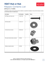
TracVision Control Panel Menu Quick Reference Guide
TracVision Control Panel Menu Quick Reference Guide
OR OR
101-110: Tracking 101
119 Menu
TriSat - Automatic ** TriSat - Manual
Tracking <SAT A>
<SAT B> Menu <SAT C>
Set Sat Select Mode?
Yes Next Return
Auto or Manual?
Auto Manual Return
Standard DualSat
Tracking <SAT A>
<SAT A> Menu <SAT B>
Return to "Set Sat Select Mode"
or "Install Satellite"
Antenna restarted
2005, KVH Industries, Inc.
* Press any button to return
Europe
Select SAT 101 and:
119 110 Return
‡
Sat Frequency Scan and Configure
Satellite functions available only in
TracVision 4/G4/6/G6 (including HP
models)
RF Flash Port
Main Flash Port
Use the latest version of the KVH Flash
Update Wizard to upgrade the software
Trisat Mode?
Yes No Return
USA or Europe?
USA Europe Return
Installing TriSat
Group - Please Wait
101, 119, and 110
sats installed
Restarting antenna
Install Europe WB?
Yes Next Cancel
Install Europe?
Yes Next Cancel
Install Scandinavia?
Yes Next Cancel
Install A <SAT NAME>
Yes Next Cancel
Install B <SAT NAME>
Yes Next Cancel
Installing sats
Please Wait
<SAT NAME> and
<SAT NAME> installed
Restarting antenna
Set brightness?
Yes Next Return
control antenna?
Yes Next Return
Get antenna status?
Yes Next Return
Upgrade software?
Yes Next Return
Return to
"Get Antenna
Status"
Select Satellite A
Select Satellite B
Install Satellite?
Yes Next Return
Restart Antenna?
Yes Next Return
Operations mode?
Yes Next Return
Sleep Mode On/Off
Set sleep on/off?
Yes Next Return
Update Frequency Data
‡
Sat frequency scan?
Yes Next Return
Man control antenna?
Yes Next Return
Adjust Azimuth/Elevation
Configure Satellite?
Yes Next Return
Set Frequency, Symbol Rate,
FEC Code, and Network ID
‡
Set Latitude/Longitude
Set Lat/Long?
Yes Next Return
Current State *
Get State?
Yes Next Return
Bit Error Rate *
Get bit error rate?
Yes Next Return
Get System Errors?
Yes Next Return
Errors Detected *
Antenna Software Versions *
Get version?
Yes Next Return
Antenna Serial Number *
Get serial number?
Yes Next Return
Threshold and Signal Levels *
Get thres/sig level?
Yes Next Return
LNB Skew Angle *
Get skew angle?
Yes Next Return
Min Bright Max
*************
Set Display Brightness
^RF Use Jack Main^
HALT Return
System Halted
Set Sat Select Mode
Auto Manual
US
** TriSat - Automatic mode only
available in USA TriSat mode
Go to
TriSat - Manual
Main Display
Go to
TriSat - Automatic
Main Display
Select SAT 101 and:
119 110 Return
Set Instant On Mode On/Off
Set instant on/off?
Yes Next Return
Set Lat/Long?
Yes Cancel
Trisat Skew Angle
##.#
Installing TriSat
Group - Please Wait
Set Lat/Long
Restarting antenna
<SAT A>, <SAT B>,
and <SAT C> installed
<MODE NAME> Mode Set

54-0260 Addendum to Rev. A
TracVision
®
HDTV Converter
Owner’s Manual Addendum
(ECO # 7162)
The following information applies to Revision A of the
TracVision HDTV Converter Kit Owner’s Manual (KVH Part
Number 54-0260).
2.4 Upgrading the Antenna Software
When you flash (upload software to) the TracVision antenna’s Main or
RF board via the control panel, you need to cycle power on both the
TracVision antenna and the control panel once flashing is complete.
This resets the communications link between the antenna and the
control panel for normal operation.
6. Wait for the wizard to finish flashing. When it is
finished, cycle power on both the TracVision
antenna and the control panel.
7. If you just flashed the RF board and need to flash
the Main board, connect the flash adapter cable to
the control panel’s Main flash port and run the
wizard again to flash the Main board. Be sure to
cycle power on the TracVision antenna and the
control panel when flashing is complete.
1

Welcome Page
KVH TracVision
®
HDTV Converter Kit
Owner’s Manual
Congratulations on your choice of the TracVision HDTV
converter! With the HDTV converter added to your TracVision
satellite TV antenna system and your HDTV receiver and HDTV
monitor, you can watch the world’s finest high-definition
programming from DIRECTV while you’re on the move.
This owner’s manual provides all of the information needed to
install, configure, operate, and troubleshoot the HDTV converter.
Please direct questions, comments, or suggestions to:
KVH Industries, Inc. KVH Europe A/S
50 Enterprise Center Kokkedal Industripark 2B
Middletown, RI 02842-5279 USA 2980 Kokkedal, Denmark
Tel: +1 401 847-3327 Tel: +45 45 160 180
Fax: +1 401 849-0045 Fax: +45 45 160 181
E-mail: [email protected] E-mail: [email protected]
Internet: www.kvh.com Internet: www.kvh.com
KVH Part # 54-0260 Rev. A
© 2005, KVH Industries, Inc. All rights reserved.
HDTV Converter Serial Number
This serial number will be required
for all troubleshooting or service
calls made regarding this product.
Click here to go to our
Customer Support web
page...the fastest and easiest
way to get all of your
questions answered.

TracVision
®
and KVH
®
are registered trademarks
of KVH Industries, Inc.
DVB
®
(Digital Video Broadcasting) is a registered trademark of the DVB Project.
DIRECTV
®
is a registered trademark of DIRECTV, Inc.,
a unit of the DIRECTV Group.
Windows® is a registered trademark of Microsoft Corporation
in the United States and other countries.

IMPORTANT
Installation Requirements
To ensure a safe and effective installation, this product should be
installed by a KVH-authorized technician. The installer should
have experience installing electronic equipment on a vessel or
vehicle.
If you have purchased the product and decide to install it
yourself, please have a KVH-authorized technician inspect and
validate your installation. (To find a technician near you, go to
www.kvh.com/wheretogetservice.) Ask the technician to fill out the
Installation Report provided with this manual, with a note
indicating that the technician has inspected and validated your
installation. Fax the completed Installation Report to KVH at
401-849-0045, or mail it to the address printed on the form.
Warranty if Installed or Validated by a KVH-authorized Technician
If a KVH-authorized technician installs the product or inspects
and validates your installation, the product is covered under the
following warranty:
Parts: 2 Years
Labor: 1 Year (Factory or Dealership)
KVH must have the Installation Report on file before any
warranty claims can be processed.
Warranty if Installed by Owner, Without Validation
If you install the product yourself, and your installation is not
inspected and validated by a KVH-authorized technician, the
product is covered under the following warranty:
Parts: 2 Years
Labor: 1 Year (Factory only)
In both cases, the warranty period begins on the date of purchase,
not the date of installation. The product’s complete warranty is
printed on the last page of this manual. Please review this page to
familiarize yourself with all requirements, liabilities, and policies.
Installation Requirements

54-0260
i
Table of Contents
Table of Contents
1 Introduction . . . . . . . . . . . . . . . . . . . . . . . . . . . . . . . . . .1
1.1 HDTV Converter Kit Overview . . . . . . . . . . . . . . . . . . . . . . . . .3
1.2 How to Use this Manual . . . . . . . . . . . . . . . . . . . . . . . . . . . . . .5
1.3 Getting Help . . . . . . . . . . . . . . . . . . . . . . . . . . . . . . . . . . . . . . .8
2 Installation . . . . . . . . . . . . . . . . . . . . . . . . . . . . . . . . . . .9
2.1 Planning the Installation . . . . . . . . . . . . . . . . . . . . . . . . . . . . .11
2.2 Wiring System Components . . . . . . . . . . . . . . . . . . . . . . . . . .14
2.3 Mounting the Control Panel . . . . . . . . . . . . . . . . . . . . . . . . . .32
2.4 Upgrading the Antenna Software . . . . . . . . . . . . . . . . . . . . . .34
2.5 Configuring the Antenna . . . . . . . . . . . . . . . . . . . . . . . . . . . . .38
2.6 Configuring the HD Receiver . . . . . . . . . . . . . . . . . . . . . . . . .42
2.7 Installation Checklist . . . . . . . . . . . . . . . . . . . . . . . . . . . . . . . .43
2.8 Testing the System . . . . . . . . . . . . . . . . . . . . . . . . . . . . . . . . .44
3 Operation . . . . . . . . . . . . . . . . . . . . . . . . . . . . . . . . . . .45
3.1 Turning On the System . . . . . . . . . . . . . . . . . . . . . . . . . . . . . .47
3.2 Using the Control Panel . . . . . . . . . . . . . . . . . . . . . . . . . . . . .47
3.3 TriSat Mode . . . . . . . . . . . . . . . . . . . . . . . . . . . . . . . . . . . . . . .48
3.4 Switching Satellites in TriSat Mode . . . . . . . . . . . . . . . . . . . . .48
3.5 How to Tell If You’re On the Wrong Satellite . . . . . . . . . . . . . .52
3.6 A Note About HDTV Programming . . . . . . . . . . . . . . . . . . . . .52
4 Control Panel Menu Functions . . . . . . . . . . . . . . . . . . . .53
4.1 The Main Menu . . . . . . . . . . . . . . . . . . . . . . . . . . . . . . . . . . . .55
4.2 Setting Satellite Select Mode . . . . . . . . . . . . . . . . . . . . . . . . .56
4.3 Installing Satellites . . . . . . . . . . . . . . . . . . . . . . . . . . . . . . . . .57
4.4 Restarting the Antenna . . . . . . . . . . . . . . . . . . . . . . . . . . . . . .59
4.5 Operations Mode . . . . . . . . . . . . . . . . . . . . . . . . . . . . . . . . . .59

54-0260
ii
TracVision HDTV Converter
5 Troubleshooting . . . . . . . . . . . . . . . . . . . . . . . . . . . . . . .71
5.1 Troubleshooting Matrix . . . . . . . . . . . . . . . . . . . . . . . . . . . . . .73
5.2 Causes and Remedies for Common
Operational Issues . . . . . . . . . . . . . . . . . . . . . . . . . . . . . . . . .74
5.3 Receiver Troubleshooting . . . . . . . . . . . . . . . . . . . . . . . . . . . .77
5.4 Computer Diagnostics . . . . . . . . . . . . . . . . . . . . . . . . . . . . . .77
5.5 Technical Support . . . . . . . . . . . . . . . . . . . . . . . . . . . . . . . . . .80
Appendices . . . . . . . . . . . . . . . . . . . . . . . . . . . . . . . . . . . . . .81
A Control Panel Specifications . . . . . . . . . . . . . . . . . . . . . . . . . .83
B Control Panel Flush Mount Template . . . . . . . . . . . . . . . . . . .85
C Wiring Diagrams . . . . . . . . . . . . . . . . . . . . . . . . . . . . . . . . . . .87
Warranty . . . . . . . . . . . . . . . . . . . . . . . . . . . . . . . . . . . . . . . . . . . . . . .89

Introduction
54-0260
1
1 – Introduction
This section provides a basic overview of the TracVision HDTV
converter and explains how to use this manual.
Contents
1.1 HDTV Converter Kit Overview . . . . . . . . . . . . . . . . . . . . . . . . . . . . . . . .3
1.2 How to Use this Manual . . . . . . . . . . . . . . . . . . . . . . . . . . . . . . . . . . . .5
1.3 Getting Help . . . . . . . . . . . . . . . . . . . . . . . . . . . . . . . . . . . . . . . . . . . . .8

1.1 HDTV Converter Kit Overview
The TracVision HDTV converter enables your DVB
®
-compatible
TracVision satellite TV antenna to track three DIRECTV satellites,
including DIRECTV’s 110ºW satellite, which offers high-
definition programming. The HDTV converter also comes with
an easy-to-use control panel that allows you to set up and
operate your antenna system.
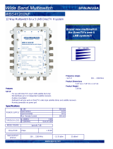
Figure 1-1 shows a typical HDTV system configuration. For
detailed system wiring diagrams, see Appendix C on page 87.
Figure 1-1
Typical HDTV System Configuration
Introduction
54-0260
3
HD Receiver 2
Receiver
Purchased Separately
TracVision Antenna
RF2
TV
HDTV 2
RF1
Laptop PC
Diagnostics Only
Switchplate or ADCU
Control Panel
12 VDC
Multiswitch
Power
HD Receiver 1 HDTV 1
HDTV Converter
Splitter
12 VDC

54-0260
4
TracVision HDTV Converter
HDTV Converter Kit Components
Your HDTV converter kit comes with the following components:
HDTV Converter
Whenever the DIRECTV 110ºW satellite is selected, the HDTV
converter alters the frequency of the satellite signal, allowing the
receiver to decode it and deliver its high-definition
programming.
Splitter
The splitter divides the tone signal from the receiver into two
signals, so that satellite switch commands can be routed to the
control panel.
Control Panel
The control panel is the user interface, providing access to the
TracVision antenna system and its functions through an LCD and
three buttons. Using the control panel, you can configure the
antenna, select satellites, check system status, and restart the
antenna.

Introduction
54-0260
5
1.2 How to Use this Manual
This owner’s manual provides all of the information you need to
install, configure, operate, and troubleshoot the HDTV converter
and control panel. For information on installing, configuring,
operating, and troubleshooting the TracVision antenna, please
refer to the manual(s) that came with the antenna.
Who Should Use This Manual
The Installer
The installing technician should follow all of the instructions
provided in the “Installation” section to ensure a safe and
effective installation. The installer should be a KVH-authorized
technician with experience installing electronic equipment on a
vessel or vehicle.
The User
The user should refer to the “Operation” section to learn how to
operate the system using the control panel. The user should also
refer to the “Control Panel Menu Functions” section for
information on the functions available through the control panel.
The User and/or Service Technician
The user and/or servicing technician should refer to the
“Troubleshooting” section to help identify the cause of a system
problem.

Typographical Conventions
This manual uses the following typographical conventions:
Icons Used in This Manual
Throughout this manual, important information is marked for
your attention by the following icons:
54-0260
6
TracVision HDTV Converter
Icon Description
A helpful tip that either directs you to a related area
within the manual or offers suggestions on getting the
most from your system
An alert to important information regarding procedures,
product specifications, or product use
Information about installation, maintenance,
troubleshooting, or other mechanical issues
An electrical saftey warning to help identify electrical
issues that can be a hazard to either this KVH product
or a user
Indicates which button to press on the control panel to
initiate a specified function
Text Example Description
Installing Trisat
Text as it appears on the control
panel display
<SAT A> and <SAT B>
installed
Text inside brackets <> is a variable
(Example: “101 and 119 installed”)
Connect the cable to the
“HDTV CONTROL” connector
(in the text)
Refers to the name of a
connector as it appears on the label
To Control Panel
(HDTV CONTROL)
(in a figure)
Refers to the name of a
connector as it appears on the label
Press the MENU button Name of a button on the control
panel
See
“Flashing the RF Board”
on page 27
for details
Cross-reference to another section
in the manual or to a web site

TracVision Product Naming Conventions
For convenience, this manual uses the following product naming
conventions:
Special Inserts in this Manual
This manual contains the following special inserts:
Control Panel Flush Mount Template
If you wish to mount the control panel flush to a vertical surface,
use the template in Appendix B on page 85 to lay out the hole
you’ll need to cut out in the mounting surface.
System Wiring Diagrams
Refer to the wiring diagrams in Appendix C on page 87 while
installing the system to ensure components are wired correctly.
Control Panel Menus Quick Reference Guide
Refer to the quick reference guide printed on the inside front
cover to view at a glance the control panel’s menu structure and
the functions available to you.
Warranty Card
Please fill out the warranty card at the back of this manual and
return it to KVH within 30 days of purchase for warranty
registration. KVH must have this card on file to validate any
future warranty claims.
Installation Report
Installer - Please complete the installation report at the back of
this manual and return it to KVH within 10 days after installing
the product. This report will be used to activate the labor
reimbursement portion of the product warranty.
Introduction
54-0260
7
Product Name in Manual Associated TracVision Models
TracVision 4 TracVision 4, TracVision 4-HP
TracVision G4 TracVision G4, TracVision G4-HP
TracVision 6 TracVision 6, TracVision 6-HP
TracVision G6 TracVision G6, TracVision G6-HP
TracVision L3, S3, C3 TracVision L3, S3, C3

1.3 Getting Help
Technical Support
If you experience an operating problem and/or need technical
assistance, please call your local authorized KVH TracVision
dealer/installer. If an authorized dealer/installer is not located
nearby, contact KVH Technical Support directly:
Phone: 1-401-847-3327
E-mail: [email protected]
Internet: www.kvh.com/help
Receiver Activation
The receiver will not be able to decode HD channels until it is
activated. High-definition channels are not included with the
basic DIRECTV package, and premium HD channels, such as
HBO HD, must be ordered separately.
If you have any questions about DIRECTV’s HD services, or if
you would like to activate your receiver, please call KVH’s
Activation Department:
Phone: 1-888-584-4163
(Monday-Friday, 8:30 am - 5:00 pm ET)
54-0260
8
TracVision HDTV Converter
Send Us Your Comments About This Manual
If you have any comments regarding this manual, please e-mail them
to [email protected]. Your feedback is greatly appreciated!

Installation
54-0260
9
2 – Installation
This section explains how to install, configure, and test the
TracVision HDTV converter system. Follow the procedures in this
section sequentially to ensure a safe and effective installation.
Contents
2.1 Planning the Installation . . . . . . . . . . . . . . . . . . . . . . . . . . . . . . . . . . .11
2.2 Wiring System Components . . . . . . . . . . . . . . . . . . . . . . . . . . . . . . . .14
2.3 Mounting the Control Panel . . . . . . . . . . . . . . . . . . . . . . . . . . . . . . . .32
2.4 Upgrading the Antenna Software . . . . . . . . . . . . . . . . . . . . . . . . . . . .34
2.5 Configuring the Antenna . . . . . . . . . . . . . . . . . . . . . . . . . . . . . . . . . . .38
2.6 Configuring the HDTV Receiver . . . . . . . . . . . . . . . . . . . . . . . . . . . . .42
2.7 Installation Checklist . . . . . . . . . . . . . . . . . . . . . . . . . . . . . . . . . . . . . .43
2.8 Testing the System . . . . . . . . . . . . . . . . . . . . . . . . . . . . . . . . . . . . . . .44

Installation
54-0260
11
2.1 Planning the Installation
Who Should Install the TracVision HDTV Converter?
KVH strongly recommends that a KVH-authorized technician
install the TracVision HDTV converter. Installers should have
experience installing electronic equipment on a vessel or vehicle.
Installing the TracVision Antenna
This manual assumes that you are adding the HDTV converter to
a TracVision antenna system that is already installed on the
vessel or vehicle. If the antenna is not yet installed, follow the
detailed instructions in the antenna’s Technical Manual or Owner’s
Manual to install and test the antenna system. Then follow the
instructions in this manual to install the HDTV converter and
control panel.
RF Board Compatibility
– RF4 or Later
The HDTV converter is compatible only with TracVision
antennas that have RF board version RF4 or later installed. If the
TracVision antenna has an RF1, RF2, or RF3 board installed, you
will need to replace the RF board. To order an RF board upgrade
kit, call KVH at 401-847-3327.
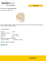
All TracVision antennas having serial number 03040001 or later
have an RF4 or RF5 board installed and are fully compatible
with the HDTV converter. You can tell which type of RF board is
installed by the shape of the board itself. As shown in Figure 2-1,
RF1, RF2, and RF3 boards have blunt corners, while RF4 and RF5
boards are square with sharp corners.
Figure 2-1
RF Boards
If you purchased the system and
decide to install it yourself, be
sure to read the important notice
at the front of this manual
regarding warranty implications.
The first four digits of the antenna
serial number indicate the year and
month (YYMM) the antenna was
manufactured. Therefore, antennas
that have a serial number starting
with 0304 were built in April 2003.
Shape of RF1, RF2,
and RF3 Boards
Shape of RF4 and RF5 Boards

54-0260
12
TracVision HDTV Converter
Materials and Equipment Required for Installation
Before you begin installing the TracVision HDTV converter,
verify that you have all of the following tools and materials:
• Electric drill
•
7
⁄16" open-end wrench and
3
⁄16" nut driver/socket
• Flat head and Phillips screwdrivers
• Light hammer; center punch; tape; scriber/pencil
• Power cable to connect control panel power (Table 2-1
provides proper gauge and length for a 12 V supply)
Table 2-1
Recommended Power Cable Specifications
Cable Length Cable Gauge
to 40 ft (12 m) 14 AWG (1.5 mm
2
)
up to 70 ft (21 m) 12 AWG (2.5 mm
2
)
• Laptop PC running Windows
®
98, ME, 2000, or XP and
equipped with a DB9 serial COM port
• HDTV receiver and HDTV monitor
Downloading the KVH Flash Update Wizard
As explained in Section 2.4, “Upgrading the Antenna Software” on
page 34, you will probably need to flash (upload software to) the
TracVision antenna to make it compatible with the HDTV
converter. Therefore, you should have the latest version of the
KVH Flash Update Wizard installed on your laptop PC before
you go to the vessel/vehicle. Download the latest version from
www.kvh.com/wizard.
If your computer does not have a
DB9 serial COM port, you can use
the following USB-to-RS232
adapter:
IOGear part number GUC232A
(visit www.iogear.com)

Installation
54-0260
13
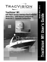
Kitpack Contents
The kitpack packaged with your HDTV converter contains
hardware and other materials that will be needed to complete the
installation. Ensure that the kitpack contains all of the items
listed below.
Table 2-2
Kitpack Contents
Part Part # Qty.
Control panel 02-1401 1
HDTV converter 02-1431 1
RF splitter 19-0366 1
Control panel mounting bracket 20-1056 1
Velcro self-adhesive backings 19-0146 2
Velcro washers 19-0147 2
#6-32 x
1
⁄2" pan head screws 14-0029-06 2
#6 flat washers 14-0024 2
#4-24 thread-forming screws 14-0150-06 4
#8 type-A black screws 14-0047-08 4
#8 lock washers 14-0038 4
Power plug 23-0478-02 1
P-clip 22-0021-04 1
Flash cable (9-pin female to stereo plug) 32-0807 1
Length: 5.9 ft (1.8 m)
Main control cable (9-pin male to 9-pin male) 32-0716-25 1
Length: 25 ft (7.6 m)
RF control cable (9-pin female to RJ11) 32-0811 1
Length: 25 ft (7.6 m)
RF control cable (9-pin female to 3 wires) 32-0618-25 1
Length: 25 ft (7.6 m)
RG6 RF cables 32-0417-28 3
Length: 28 ft (8.5 m)
RG179 RF cables 32-0442-18 2
Length: 1.5 ft (45.7 cm)
Snap-N-Seal
®
F-connector 23-0170 1
Switchplate maintenance port assembly:
TracVision 4/6/G4/G6 version 02-1192 1
OR
TracVision C3/L3/S3 version 02-1192-01 1
If you need to cut any RF cable to a
certain length, be sure to attach a
Snap-N-Seal F-connector to the
end of the cable using an LRC/
Augat T1000 crimp/strip tool. Do
not use a screw-on, push-on, twist-
on, or any other over-the-counter
connector. Such low-quality
connectors WILL degrade system
performance and KVH does not
warrant their use.

Choosing the Best Location for the Control Panel
• The control panel should be located in a dry
location, allowing enough room at the back for
connecting the various cables.
• Control panel dimensions: 8.2" (20.8 cm) wide x
3" (76.2 cm) deep x 2.6" (6.6 cm) high
• The control panel should be placed so that the
LCD display is visible and the buttons are
accessible to the user.
• The control panel is not susceptible to magnetic
interference and does not need to be mounted on a
level surface.
2.2 Wiring System Components
Wiring instructions vary depending on the antenna system’s
model and configuration. Table 2-3 lists the six possible system
configurations.
Table 2-3
System Configurations
54-0260
14
TracVision HDTV Converter
Before connecting any cables, turn
off vessel/vehicle power and test
the circuit to ensure that no power
is present.
One HD Receiver
(option for a 2nd,
non-HD receiver)
Multiswitch Installed
(multiple HD or
standard receivers)
TracVision 4/6
A B
TracVision G4/G6
C D
TracVision C3/L3/S3
E F
Wiring Diagrams in Appendix C
Detailed wiring diagrams for all six configurations are
provided in Appendix C on page 87. Find the diagram for your
configuration and, as you connect each cable, mark an “X”
over the corresponding line in the diagram. Once you’ve
completed the installation, you will then be able to refer to the
diagram to easily verify that you’ve connected all of the
necessary cables.
/