Page is loading ...

R5A/W, T5A/W
D5A/W Icemaker
Operation, Service and Parts Manual
Service number 5022501 and above
207654R01
®
®
U
L
®
R5A icemaker with countertop dispenser
T5A/W icemaker mounted on ice storage bin
R5A icemakers with undercounter dispenser
801 Church Lane • PO Box D, Easton, PA 18044
Toll free (800) 523-9361 • (888) 2-FOLLETT
(610) 252-7301 • Fax (610) 250-0696 • www.follettice.com
Order parts online
www.follettice.com

Welcome to Follett
Follett icemakers enjoy a well-deserved reputation for excellent performance, long-term reliability and outstanding
after-the-sale support. To ensure that your icemaker delivers this high performance, we ask that you review the
cleaning instructions on this page and retain this manual on file for use by the service technicians maintaining the
unit. Should you have any questions or require technical help at any time, please call our technical service group
at (800) 523-9361, (888) 2-FOLLETT or (610) 252-7301.
Table of contents
Preventive maintenance information Page 1
Cleaning instructions 2 - 3
Overview of Follett icemaking process 3
Normal operation circuit sequences 4 - 6
Diagnostic circuit sequences 7 - 8
T5A/W icemaker circuitry (used on ice storage bin) 9
Refrigeration cycle diagram 9
Test data 10
Refrigeration system 11
Disassembly instructions 12
Troubleshooting guide 13 - 14
Replacement parts 15 - 23
Important operator information
Cleaning procedures
Recommended monthly cleaning of condenser (air-cooled icemaker only)
1. Use vacuum cleaner or stiff brush to carefully clean condenser coils of air-cooled icemaker to ensure optimal
performance.
2. When reinstalling counter panels in front of remote icemakers, be sure ventilation louvers line up with
condenser air duct.
Preventive maintenance
Periodic cleaning of Follett’s icemaker system is required to ensure peak performance and delivery of clean,
sanitary ice. The recommended cleaning procedures which follow should be performed at least as frequently as
recommended below and more often if environmental conditions dictate.
Cleaning of the condenser can usually be performed by facility personnel. Cleaning of the icemaker system in
most cases should be performed by your facility’s maintenance staff or a Follett authorized service agent.
Regardless of who performs the cleaning, it is the operator’s responsibility to see that this cleaning is performed
according to the schedule below. Service problems resulting from lack of preventive maintenance will not be
covered under the Follett warranty.

Recommended quarterly cleaning of icemaking system
The icemaking system can be cleaned in place without disassembling the water system. This cleaning process
should be performed at least every 3 months, and more often if local water conditions dictate.
1. Disconnect power to icemaker.
2. Remove any icemaker panels required to gain access to water reservoir and electrical control box.
3. Turn compressor switch on electrical box of icemaker to OFF position.
4. Remove water reservoir cover and block up reservoir float.
5. Drain water from reservoir and evaporator by removing tygon hose from bottom of reservoir.
Note: Some models have an evaporator drain hose teed off evaporator supply hose.
6. Following manufacturer's instructions, prepare 3 pints (1.4L) of Calgon Ice Machine Cleaner or equivalent.
Cleaning solution temperature must be 65° – 85°F (18° – 29°C).
7. Replace tygon hose on bottom of reservoir or plug evaporator drain hose, and pour part of cleaning solution
into reservoir, filling it almost to overflowing.
Note: If your icemaker has a stainless steel compression nozzle, remove it and submerge it in a cup of
cleaning solution while cleaning rest of system.
8. Restore power to icemaker (gearmotor will now run, but compressor and fan motor will not run).
9. After 15 minutes, turn power off and drain cleaning solution from reservoir and evaporator.
10. Replace tygon hose on reservoir, close evaporator drain valve or plug drain hose.
11. Rinse compression nozzle in clean water and reinstall on evaporator outlet.
12. Following manufacturer's instructions, prepare 1 gallon (3.8L) of Calgon Ice Machine Sanitizer or equivalent.
Sanitizing solution temperature must be 65° - 85°F (18° - 29°C).
13. If ice bin cleaning is also needed at this time, remove all ice from ice storage area and allow ice made during
the sanitizing process to fall into ice bin area.
Note: If bin will not be cleaned at this time, place a large pan in bin storage area to catch ice or connect a
separate ice transport tube to evaporator and divert ice into separate container.
14. Fill reservoir almost to overflowing with sanitizing solution.
15. Restore power to icemaker and turn compressor switch to ON position.
16. As unit starts to make ice, continue to pour sanitizing solution into reservoir, maintaining level just below
reservoir overflow.
17. Continue to make ice until you have used 1/2 gallon (1.9L) of sanitizing solution.
18. Unblock float, replace reservoir cover, and continue to make ice for at least 15 minutes to flush all sanitizing
solution from system (icemakers installed in remote locations with long ice transport hoses may take longer).
19. Switch compressor switch to OFF position.
20. Wash bin with remaining sanitizing solution and rinse with potable water.
21. Switch compressor switch to ON position.
22. Replace any panels removed prior to cleaning.
Important preliminary information
Follett's icemaker consists of four distinct functional systems.
• Refrigeration system
•Water system
• Harvesting system
• Electrical control system
These four systems work together to accomplish the production and harvesting of ice. A problem in any one of
these system areas will result in improper operation of the entire ice production cycle. When troubleshooting the
icemaker, it is important to analyze the entire system operation to determine which system is not functioning
properly, then pinpoint the component within that system that is malfunctioning. Determine what corrective action
must be taken before making any adjustments or replacing any components.
2
WARNING: Most ice machine cleaners contain citric or phosphoric acid which can
cause skin irritation. Read caution label on product and follow instructions carefully.
!

The icemaking process
The Follett icemaker uses a wrapped tube evaporator and operates on a continuous freezing cycle. Water is supplied
to the evaporator from the water reservoir where the water level is controlled by a float valve. This valve also shuts off
the water supply when the icemaker is not running.
When the icemaker is running, a layer of ice forms on the interior surface of the evaporator. This ice is continuously
removed by a slowly rotating (12 RPM) auger. The auger carries the ice upward into the cavity formed by the top
bearing housing and the compression loop, where it is compressed to remove excess water. When the ice reaches
the desired hardness it rotates within the cavity and is forced through a discharge port and compression nozzle and
into the ice transport tube. The discharge tube and compression nozzle are slightly restricted to further compress the
ice and produce the desired high quality. As the formation of ice continues, ice in the transport tube is pushed through
the tube to the storage compartment in the ice dispenser or ice storage bin.
A solid state control board located in the electrical box of the icemaker controls the normal operation of the icemaker
and monitors gearmotor torque on an ongoing basis. This control board will shut down the icemaker should an over
torque condition occur. It is very important that you familiarize yourself with the operational sequences detailed in this
manual before attempting to service the icemaker.
Operational and diagnostic sequences
The wiring diagrams which follow illustrate the circuitry of Follett icemakers used with ice dispensers. Both normal
operation of the icemaker (stages 1 - 6) and non-normal diagnostic sequences showing torque-out (stages 7 - 9)
for use in troubleshooting icemaker problems are shown.
Follett icemakers used on top of an ice storage bin have a slightly different circuitry. A diagram for this type of
icemaker is shown on page 9. The operational and diagnostic stages for these icemakers will be otherwise the
same as stages 1 - 9 that follow.
3
When the icemaker is used with a dispenser it receives power from two sources –
the main power supply and the bin control signal power from the dispenser.
Disconnect both power sources before performing mechanical service. When
performing electrical service, always use a meter to determine whether or not the
components being serviced are energized.
!
Circuitry notes
• Hi-temp safety thermostat (water-cooled only) opens at 125°F/50°C, and closes at 115°F/46°C
• Compressor switch should read open in ON position
• Alternate input power for some non-domestic units will be 230V, 50Hz
• Compressor start relay is position sensitive. See label on start relay for proper orientation.
• Bin signal may be 120V, 60Hz; 230V, 50Hz; or 24V, 60Hz. If bin signal is 24V, 60Hz, black wire must be
moved from LINE VAC terminal to 24V terminal.
• Flashing water LED at any time indicates that water signal to board had been lost for more than one second
• Ten-second delay: There is a 10 second delay in reaction to loss of water (WTR) or bin (B-E) signals. If
signals are not lost for more than 10 seconds, no reaction will occur.

Normal operation – Stage 1
Power is supplied to L1 of the control board. The ice level control in the dispenser is closed and calling for ice,
supplying signal voltage to the control board. The control board will now go through the start up sequence. Less
than 30 seconds will elapse as the water sensor located in the float reservoir checks for water in the reservoir.
The Bin Empty LED (B-E) will be on.
Normal operation – Stage 2
The water sensor verifies water in the float. The Water OK LED (WTR) comes on. At the same time, the
gearmotor, compressor, and condenser fan motor come on, lighting the Drive LED (DR) and compressor LED
(C). The compressor is started through a current style relay that is pulled in by the initial high current draw of the
compressor. The B-E and WTR LED remain on.
M
GRD
L1
L1
L2
L2
L2
L2
L2
COMPRESSOR
FAN
DRIVE
DR
C
20M
60M
2ND
WTR
B-T
B-E
RESET
X
GRD
G
B
W
FAN
BLACK
WHITE
BLACKBLACK
R
ORANGE
S
S
L
COMPRESSOR
C
RED
BLACK
BLACK
WHITE
INPUT
POWER
CONTROL
BOARD
BLACK
GEARMOTOR
24V
COMMON
LINE VAC
RED
RED
WHITE
BLACK
BIN T-STAT
BIN SIGNAL
FROM DISPENSER
JUNCTION BOX
WHITE
RED
WHITE
M
1
4
3
L1
L2
HI-TEMP SAFETY
T-STAT (W/C ONLY)
COMPRESSOR
SWITCH
WATER
SENSOR
PWR
4
M
GRD
L1
L1
L2
L2
L2
L2
L2
COMPRESSOR
FAN
DRIVE
DR
C
20M
60M
2ND
WTR
B-T
B-E
RESET
X
GRD
G
B
W
FAN
BLACK
WHITE
BLACKBLACK
R
ORANGE
S
S
L
COMPRESSOR
C
RED
BLACK
BLACK
WHITE
INPUT
POWER
CONTROL
BOARD
BLACK
GEARMOTOR
24V
COMMON
LINE VAC
RED
RED
COMPRESSOR
SWITCH
WHITE
BLACK
BIN T-STAT
BIN SIGNAL
FROM DISPENSER
JUNCTION BOX
WHITE
RED
WHITE
M
1
HI-TEMP SAFETY
T-STAT (W/C ONLY)
4
3
L1
L2
WATER
SENSOR
PWR

Normal operation – Stage 3
The gearmotor comes up to its normal running speed and the centrifugal switch located in the gearmotor opens,
dropping out the start winding. As the compressor comes up to normal running speed, the compressor start relay
contacts open, dropping out the start winding of the compressor. The icemaker is now in a normal icemaking
mode. The icemaker will begin to produce ice and continue to produce ice until the bin level control in the ice
dispenser is satisfied. The B-E, DR, C and WTR LEDs are all on.
Normal operation – Stage 4
Once the ice level control opens, the B-E LED goes out. After a 10 second delay the LED (C), compressor, and
fan motor go off. (Should the ice level control not remain open for 10 seconds, the ice maker will continue to run.)
The gearmotor continues to run for 60 seconds. The purpose of this function is to drive the remaining ice out of
the evaporator and to boil off any refrigerant remaining in the evaporator.
M
GRD
L1
L1
L2
L2
L2
L2
L2
COMPRESSOR
FAN
DRIVE
DR
C
20M
60M
2ND
WTR
B-T
B-E
RESET
X
GRD
G
B
W
FAN
BLACK
WHITE
BLACKBLACK
R
ORANGE
S
S
L
COMPRESSOR
C
RED
BLACK
BLACK
WHITE
INPUT
POWER
CONTROL
BOARD
BLACK
GEARMOTOR
24V
COMMON
LINE VAC
RED
RED
COMPRESSOR
SWITCH
WHITE
BLACK
BIN T-STAT
BIN SIGNAL
FROM DISPENSER
JUNCTION BOX
WHITE
RED
WHITE
M
1
4
3
L1
L2
HI-TEMP SAFETY
T-STAT (W/C ONLY)
WATER
SENSOR
PWR
5
M
GRD
L1
L1
L2
L2
L2
L2
L2
COMPRESSOR
FAN
DRIVE
RESET
X
GRD
G
B
W
FAN
BLACK
WHITE
BLACKBLACK
R
ORANGE
S
S
L
COMPRESSOR
C
RED
BLACK
BLACK
WHITE
INPUT
POWER
CONTROL
BOARD
BLACK
GEARMOTOR
24V
COMMON
LINE VAC
RED
RED
COMPRESSOR
SWITCH
WHITE
BLACK
BIN T-STAT
BIN SIGNAL
FROM DISPENSER
JUNCTION BOX
WHITE
RED
WHITE
M
1
HI-TEMP SAFETY
T-STAT (W/C ONLY)
4
3
L1
L2
WATER
SENSOR
DR
C
20M
60M
2ND
WTR
B-T
B-E
PWR

Normal operation – Stage 5
The B-T LED will remain on for 20 minutes. The icemaker will not start while the B-T LED is on. To restart the
icemaker for troubleshooting purposes, depress the reset button to clear the control board.
Normal operation – Stage 6
When the dwell time of 20 minutes has expired, the B-T LED goes off. The icemaker will go through the normal
start up sequence when the bin level control signals the control board for ice. The WTR LED will remain on as
long as the water sensor in the float reservoir senses water
M
GRD
L1
L1
L2
L2
L2
L2
L2
COMPRESSOR
FAN
DRIVE
DR
C
20M
60M
2ND
WTR
B-T
B-E
RESET
X
GRD
G
B
W
FAN
BLACK
WHITE
BLACKBLACK
R
ORANGE
S
S
L
COMPRESSOR
C
RED
BLACK
BLACK
WHITE
INPUT
POWER
CONTROL
BOARD
BLACK
GEARMOTOR
24V
COMMON
LINE VAC
RED
RED
COMPRESSOR
SWITCH
WHITE
BLACK
BIN T-STAT
BIN SIGNAL
FROM DISPENSER
JUNCTION BOX
WHITE
RED
WHITE
M
1
HI-TEMP SAFETY
T-STAT (W/C ONLY)
4
3
L1
L2
WATER
SENSOR
PWR
6
M
GRD
L1
L1
L2
L2
L2
L2
L2
COMPRESSOR
FAN
DRIVE
DR
C
20M
60M
2ND
WTR
B-T
B-E
RESET
X
GRD
G
B
W
FAN
BLACK
WHITE
BLACKBLACK
R
ORANGE
S
S
L
COMPRESSOR
C
RED
BLACK
BLACK
WHITE
INPUT
POWER
CONTROL
BOARD
BLACK
GEARMOTOR
24V
COMMON
LINE VAC
RED
RED
COMPRESSOR
SWITCH
WHITE
BLACK
BIN T-STAT
BIN SIGNAL
FROM DISPENSER
JUNCTION BOX
WHITE
RED
WHITE
M
1
HI-TEMP SAFETY
T-STAT (W/C ONLY)
4
3
L1
L2
WATER
SENSOR
PWR

Diagnostic sequence – Stage 7
The 20 Minute Error LED (20M) is on indicating that the control board has sensed an over-torque condition
(above 3.5 AMPS on the gearmotor). The 20M LED will remain on for 20 minutes after an over-torque condition
has occurred. The icemaker will remain off as long as the 20M LED is on. When the 20M LED goes off, the
control board will try to go through a normal start up sequence. The WTR LED remains on as long as the water
sensor in the float reservoir senses water.
Diagnostic sequence – Stage 8
When the 20M LED goes off, the 60 Minute Timer LED (60M) comes on. The 60M LED will remain on for 60
minutes from restart. A lighted 60M LED tells the technician that the icemaker has experienced an over-torque
condition. If the icemaker runs without problems for 60 minutes and no additional torque errors occur, the 60M
LED will go off.
M
GRD
L1
L1
L2
L2
L2
L2
L2
COMPRESSOR
FAN
DRIVE
DR
C
20M
60M
2ND
WTR
B-T
B-E
RESET
X
GRD
G
B
W
FAN
BLACK
WHITE
BLACKBLACK
R
ORANGE
S
S
L
COMPRESSOR
C
RED
BLACK
BLACK
WHITE
INPUT
POWER
CONTROL
BOARD
BLACK
GEARMOTOR
24V
COMMON
LINE VAC
RED
RED
COMPRESSOR
SWITCH
WHITE
BLACK
BIN T-STAT
BIN SIGNAL
FROM DISPENSER
JUNCTION BOX
WHITE
RED
WHITE
M
1
HI-TEMP SAFETY
T-STAT (W/C ONLY)
4
3
L1
L2
WATER
SENSOR
PWR
7
M
GRD
L1
L1
L2
L2
L2
L2
L2
COMPRESSOR
FAN
DRIVE
DR
C
20M
60M
2ND
WTR
B-T
B-E
RESET
X
GRD
G
B
W
FAN
BLACK
WHITE
BLACKBLACK
R
ORANGE
S
S
L
COMPRESSOR
C
RED
BLACK
BLACK
WHITE
INPUT
POWER
CONTROL
BOARD
BLACK
GEARMOTOR
24V
COMMON
LINE VAC
RED
RED
COMPRESSOR
SWITCH
WHITE
BLACK
BIN T-STAT
BIN SIGNAL
FROM DISPENSER
JUNCTION BOX
WHITE
RED
WHITE
M
1
HI-TEMP SAFETY
T-STAT (W/C ONLY)
4
3
L1
L2
WATER
SENSOR
PWR

Diagnostic sequence – Stage 9
The second error (2ND) LED will come on if an over-torque condition occurs while the 60M LED is still lighted.
The 2ND LED will indicate to the technician that two consecutive over-torque situations have occurred. The
icemaker will be shut down at this time and will not restart unless the manual reset button is depressed.
M
GRD
L1
L1
L2
L2
L2
L2
L2
COMPRESSOR
FAN
DRIVE
DR
C
20M
60M
2ND
WTR
B-T
B-E
RESET
X
GRD
G
B
W
FAN
BLACK
WHITE
BLACKBLACK
R
ORANGE
S
S
L
COMPRESSOR
C
RED
BLACK
BLACK
WHITE
INPUT
POWER
CONTROL
BOARD
BLACK
GEARMOTOR
24V
COMMON
LINE VAC
RED
RED
COMPRESSOR
SWITCH
WHITE
BLACK
BIN T-STAT
BIN SIGNAL
FROM DISPENSER
JUNCTION BOX
WHITE
RED
WHITE
M
1
HI-TEMP SAFETY
T-STAT (W/C ONLY)
4
3
L1
L2
WATER
SENSOR
PWR
8
Diagnostic sequence - Stage 10
If the water level in the float reservoir drops to an unacceptable level, the WTR LED will go out, shutting the
icemaker off. Also, the BT LED will come on, preventing the icemaker from restarting for twenty minutes. If water
is restored, the WTR LED will come back on and flash to alert the technician that water to icemaker has been
lost. The icemaker will then restart at the end of the 20 minute time delay. The flashing WTR LED can be cleared
by pressing the reset button.
M
GRD
L1
L1
L2
L2
L2
L2
L2
COMPRESSOR
FAN
DRIVE
DR
C
20M
60M
2ND
WTR
B-T
B-E
RESET
X
GRD
G
B
W
FAN
BLACK
WHITE
BLACKBLACK
R
ORANGE
S
S
L
COMPRESSOR
C
RED
BLACK
BLACK
WHITE
INPUT
POWER
CONTROL
BOARD
BLACK
GEARMOTOR
24V
COMMON
LINE VAC
RED
RED
WHITE
BLACK
BIN T-STAT
BIN SIGNAL
FROM DISPENSER
JUNCTION BOX
WHITE
RED
WHITE
M
1
4
3
L1
L2
HI-TEMP SAFETY
T-STAT (W/C ONLY)
COMPRESSOR
SWITCH
WATER
SENSOR
PWR

T5A/W icemaker circuitry
Follett icemakers used on top of an ice storage bin (T5A/W) have a slightly different circuitry. A diagram for these
icemakers is shown below. The operational and diagnostic stages for these icemakers will be otherwise the same
as the preceding stages 1 - 10.
M
GRD
L1
L1
L2
L2
L2
L2
L2
COMPRESSOR
FAN
DRIVE
DR
C
20M
60M
2ND
WTR
B-T
B-E
RESET
X
GRD
G
B
W
FAN
BLACK
WHITE
BLACKBLACK
R
ORANGE
S
S
L
COMPRESSOR
C
RED
BLACK
BLACK
WHITE
INPUT
POWER
CONTROL
BOARD
BLACK
GEARMOTOR
24V
COMMON
LINE VAC
RED
RED
COMPRESSOR
SWITCH
WHITE
BLACK
BIN T-STAT
WHITE
M
1
HI-TEMP SAFETY
T-STAT (W/C ONLY)
4
3
L1
L2
WATER
SENSOR
PWR
9
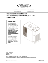
condenser
filter
drier
thermostatic
expansion
valve
evaporator
compressor
high side
service port
low side
service port
high
pressure
vapor
high
pressure
liquid
low
pressure
liquid
low
pressure
vapor
Refrigeration cycle

Table 1 – Refrigeration pressure data*
Ambient 50°F 55°F 60°F 65°F 70°F 75°F 80°F 85°F 90°F 95°F 100°F 110°F
air temp. 10°C 12.7°C 15.6°C 18.3°C 21.1°C 23.9°C 26.7°C 29.4°C 32.2°C 35°C 37.8°C 43.3°C
Water temp. 50°F 55°F 60°F 65°F 70°F 75°F 80°F 85°F 90°F 95°F 100°F 105°F
at float 10°C 12.7°C 15.6°C 18.3°C 21.1°C 23.9°C 26.7°C 29.4°C 32.2°C 35°C 37.8°C 40.6°C
Air-cooled
Suction pressure
PSIG 30 31 32 33 34 35 35 36 37 38 39 41
Discharge pressure
PSIG 155 167 178 192 200 210 223 238 250 269 288 310
Water-cooled
Suction pressure
PSIG 32 32 33 33 34 35 35 35 36 37 39 40
Discharge pressure
PSIG 185 185 185 185 185 185 185 185 185 185 212 229
* Notes: 1) Water regulating valve is factory set at 185 PSIG head pressure.
2) Readings within 10% of above table values should be considered normal.
Table 2 – Compressor data
Compressor current draw
Air-cooled
Ambient air temp. 60°F/15.6°C 70°F/21.1°C 80°F/26.7°C 90°F/32.2°C 100°F/37.8°C
6.3A 6.5A 6.7A 6.9A 7.1A
Water-cooled
Water temp. at float 50°F/10°C 60°F/15.6°C 70°F/21.1°C 80°F/26.7°C 90°F/32.2°C
6.6A 6.7A 6.7A 6.8A 6.9A
Locked rotor amps 48.0
Water-cooled icemaker capacity/24 hours
Table 3 – Gearmotor data
Gearmotor current 2.25A (nominal)
Locked rotor amps 14 amps
10
Inlet Water Temperature °F/°C
Ambient Air Temperature °F/°C
Inlet Water Temperature °F/°C
50° 475 470 465 460 450 lbs.
F° 60° 70° 80° 90° 100°
C° 16° 21° 27° 32° 38°
10° 215 213 211 209 204 kg.
60° 445 435 430 420 415 lbs.
16° 202 197 195 191 188 kg.
70° 415 410 400 390 380 lbs.
21° 188 186 181 177 172 kg.
80° 390 380 370 360 350 lbs.
27° 177 172 168 163 159 kg.
90° 370 360 350 340 325 lbs.
32° 168 163 159 154 147 kg.
Ambient Air Temperature °F/°C
50° 570 515 465 410 360 lbs.
F° 60° 70° 80° 90° 100°
C° 16° 21° 27° 32° 38°
10° 259 234 211 186 163 kg.
60° 535 495 450 405 340 lbs.
16° 243 225 204 184 154 kg.
70° 480 440 400 360 320 lbs.
21° 218 200 181 163 145 kg.
80° 465 425 390 350 315 lbs.
27° 211 193 177 159 143 kg.
90° 420 385 350 310 275 lbs.
32° 191 175 159 141 125 kg.
Air-cooled icemaker capacity/24 hours

Refrigeration system
Important: All service on refrigeration systems must be performed in accordance with all federal, state and local
laws that pertain to the use of refrigerants. It is the responsibility of the technician to ensure that
these requirements are met.
Refrigerant replacement requirements
1. Non-contaminated refrigerant removed from any Follett refrigeration system can be recycled and returned to
the same system after completing repairs. Recycled refrigerant must be stored in a clean, approved storage
container. If additional refrigerant is required, virgin or reclaimed refrigerant that meets ARI standard 700-88
must be used.
2. In the event of system contamination (for example, a compressor burn out, refrigerant leak, presence of non-
condensibles or moisture), the system must be repaired, evacuated and recharged using virgin or reclaimed
refrigerant that meets ARI standard 700-88.
3. Follett Corporation does not approve of recovered refrigerants. Improper refrigeration servicing procedures
will void the factory warranty.
Evacuation
Evacuate the system to a level of 50 microns. When the 50 micron level is reached, shut the vacuum pump down.
Allow the system to sit for approximately 30 seconds. During this period the system should not rise above 1000
microns. If the system rises above 1000 microns, evacuate the system again. If the system rises above 1000
microns for a second time, check the system for leaks.
Ambients Minimum Maximum
Air Temperature
1
50°F/10°C 100°F/37.8°C
Water Temperature
2
40°F/4.4°C 90°F/32.2°C
1
Ambient air temperature is measured at the air-cooled condenser coil inlet.
2
Ambient water temperature is measured in the icemaker float reservoir.
Ice capacity test
Icemaker production capacity can only be determined by weighing ice produced in a specific time period.
1. Replace all panels on icemaker.
2. Run icemaker for at least 15 minutes.
3. Weigh and record weight of container used to catch ice.
4. Catch ice for 15 or 20 minutes.
5. Weigh harvested ice and record total weight.
6. Subtract weight of container from total weight.
7. Convert fractions of pounds to decimal equivalents (ex. 6 lbs 8 oz = 6.5 lbs).
8. Calculate production using following formula:
1440 min. x wt. of ice produced
= Production capacity/24 hr. period
Total test time in minutes
9. Calculated amount per 24 hours should be checked against rated capacity for same ambient and water
temperatures in Ice Production Tables.
R22 icemaker charge specifications
Model Charge Refrigerant type
T5A, R5A , L5A (air-cooled) 24 oz R22
T5W, R5W , L5W (water-cooled) 10 oz R22
11
Recharging of unit at other than factory specifications will void icemaker
warranty.
!

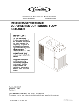
Evaporator disassembly
Note: The upper and lower bearing assemblies and auger assembly must be replaced as assemblies. The
bottom and top bearing assemblies cannot be field assembled to factory specifications.
1. Disconnect power to icemaker.
2. Shut off water to icemaker.
3. Drain evaporator and float tank.
4. Disconnect plastic tubing from evaporator water inlet.
5. Disconnect ice transport tube from compression nozzle.
6. Remove nut and upper vee band coupling from top of evaporator
(see pg. 19).
7. Lift top bearing assembly straight up with a slight rocking motion and
remove.
8. Remove ice compression loop located at top of auger.
9. Lift auger straight up and out of evaporator.
10. Remove nut and lower vee band coupling from bottom of evaporator.
11. Lift evaporator to clear bottom bearing assembly.
12. Loosen hex head bolt in side of mounting base with 5/16 wrench and lift
lower bearing assembly.
13. Remove condensate shield.
14. Remove four Allen head machine screws holding mounting base to
gearbox.
15. If replacing evaporator, remove compression nozzle from evaporator
port.
Evaporator reassembly
1. Clean gearmotor boss, output shaft and shaft well.
2. Degrease OD of gear motor boss.
3. Apply 242 Loctite to OD of boss and install evaporator mounting base.
4. Fill gearmotor shaft well with food grade grease.
5. Install condensate shield and seat against gearmotor boss.
6. Install bearing O ring in groove in evaporator mounting base.
7. Lower bottom bearing assembly into evaporator mounting base.
8. While maintaining a slight downward pressure on bottom bearing
assembly, tighten hex head bolt with a 5/16 wrench.
9. Position evaporator over lower bearing assembly and align grooves
with pins in bearing assembly.
10. Align lower portion of compression nozzle drip guide (if so
equipped) inside evaporator drain pan.
11. Install vee band clamp and nut.
12. Place auger in center of evaporator and rotate to mate with spline.
13. Install ice compression loop, orienting loop as shown on page 19.
14. Install upper bearing and seal assembly, rotating bearing to slip pin
into auger slot.
15. Install upper vee band clamp and nut.
16. If evaporator was replaced, reinstall compression nozzle on new.
Gearmotor replacement
1. Disassemble evaporator as described above.
2. Remove gearmotor drip cap by tapping up on flange at edge of cap.
3. Remove gearmotor cover plate and disconnect the wires.
4. Remove Heyco wire bushing and pull wires out.
5. Remove four screws holding gearmotor mounting plate to base of icemaker and lift gearbox and motor clear
of icemaker.
6. Remove machine screws holding mounting plate to motor.
7. Install new motor in reverse order.
12
compression nozzle
drip guide
apply grease
here
Loctite

Problem
1. Icemaker will not run.
System status:
compressor, gearmotor,
and fan motor inoperative.
2. Compressor will not run.
System status: gearmotor
and fan motor run.
3. Unit cycles intermittently.
System status:
compressor, gearmotor,
and fan motor cycle.
4. Low ice production.
Poor quality ice.
Indicators/possible cause
1. No power to unit.
2. Open bin level control.
3. Water OK LED (WTR) not on.
4. 20M or 2ND LED is on indicating that first
or second torque error has occurred.
5. Gearmotor locked up (immediate torque
error indicated by LEDs when board is
reset).
6. Centrifugal switch stuck in open or closed
position (immediate torque error indicated
by LEDs when board is reset).
1. Condenser coil plugged causing
overheating.
2. Defective starting capacitor.
3. Defective starting relay.
4. Open motor winding.
5. No power output from compressor output
terminal on control board.
1. Hi temp cut out open (W/C units only)
due to high head pressure.
2. Float reservoir running dry, sensing
probe signalling for system to shut down.
1. Dirty condenser coil.
2. Restricted air flow to condenser coil.
3. Mineral coated evaporator.
4. High ambient water supply and/or air
temperature.
5. Improper exhaust air provisions.
6. Faulty expansion valve.
7. Low refrigerant charge.
8. Superheat incorrect.
9. Inefficient compressor.
Corrective action
1. Check that unit is plugged in, circuit
breakers are on.
2. Adjust or replace ice level control.
3. Check reservoir for water, restore
water to unit.
4. See Problem #6 below.
5. Repair or replace gearmotor.
6. Replace centrifugal switch.
1. Clean condenser coil and replace
overload if necessary.
2. Replace start capacitor.
3. Replace relay.
4. Ohm out windings and replace
compressor if necessary.
5. Check terminal connection and
replace control board if necessary.
1a. Check supply and temperature of
water to condenser.
1b. Check discharge pressure and
adjust water regulating valve.
1c. Clean condenser coil.
2. Check water supply to float and
float operation. Part #207588 will
have flashing WTR LED.
1. Clean condenser.
2. Remove obstruction.
3. Clean evaporator.
4. Precool water and/or install air duct
per Follett installation manual.
5. Provide proper exhaust air
provisions per Follett installation
manual.
6. Replace expansion valve.
7. Check for leaks; repair, evacuate,
and weigh in correct charge.
8. Check that TEV sensing bulb is
securely clamped in place and not
damaged; check that insulated bulb
cover is in place.
9. Replace compressor.
Troubleshooting chart
• Flashing water LED at any time indicates that water signal to board has been lost for more than one second.
• Ten-second delay: There is a 10 second delay in reaction to loss of water (WTR) or bin (B-E) signals. If signals
are not lost for more than 10 seconds, no reaction will occur.
13

5. Water leaks from bottom of
evaporator.
6. Icemaker runs for short
period of time and shuts
down on torque error.
System status: 20M or 2nd
LED are lit.
7. Evaporator is iced up on
the outside. No ice
production.
System status:
compressor, gearmotor and
fan motor running.
8. Compressor cycles
intermittently.
System status: gearmotor
and fan motor run.
9. Unit runs but not making
ice.
System status:
compressor, gearmotor and
fan motor running.
10. Compressor and fan motor
will not run. Gearmotor
runs.
1. O ring seal broken.
1. Kink in ice transport tube.
2. Bin level control remains in closed
position.
3. Ice transport tube ruptured internally.
4. Worn evaporator bearings.
5. Faulty centrifugal switch. Icemaker
torques out within 5 seconds of start-up.
6. Torque out occurs when storage bin fills
to capacity.
1. Gearmotor running but no output
rotation.
2. Float reservoir empty.
1. Compressor start relay in wrong
position.
2. Intermittent voltage from circuit board to
compressor.
3. Clogged or dirty condenser coil.
4. Improper ventilation.
5. Defective compressor.
1. Clogged or dirty condenser coil.
2. Compressor not pumping.
3. Low refrigerant charge.
1. Compressor switch in OFF position.
2. No output on compressor and fan motor
terminals on control board.
1. Replace O ring.
1. Eliminate kink and check that tube
routing complies with Follett
icemaker installation manual.
2. Adjust or replace control.
3. Replace complete run of ice
transport tube.
4. Inspect bearings for roughness or
binding and replace if necessary.
5. Replace centrifugal switch.
6. Ensure that ice contacts bin
thermostat before backing ice up in
transport tube. Reference dispenser
manual for proper thermostat and
ice tube mounting.
1. Check for broken gearmotor output
shaft or damaged gearbox.
2. Check for defective water sensor
(water OK (WTR) LED remains on
even when float empty or probe
removed from water).
1. Position relay with arrow or word
“top”.
2. Check for constant line voltage
output on board compressor
terminal and replace board if
intermittent.
3. Clean condenser coil.
4. Provide inlet and exhaust air
provisions per Follett icemaker
installation manual.
5. Replace compressor.
1. Clean condenser coil.
2. Replace compressor.
3. Check for leaks; repair, evacuate,
and weigh in correct charge.
1. Turn compressor switch on.
2. Replace control board.
Troubleshooting chart
14

Air-cooled icemaker – right side
Air-cooled icemaker – left side
15
1
2
3
4
5
6
7
11
10
12
8
9
12
6
5
16
17
15
14
13
2
18

Part # Description Reference #
501581 Drier 1
501187 Condenser coil, a/c 2
502116 Water sensor 3
500504 Float valve & reservoir 4
501986 Reservoir mounting bracket Not shown
502079 Tubing, polypropylene, reservoir supply (sold by foot) Not shown
502078 Fitting, plastic, float valve (includes sleeve & stem) Not shown
502220 Compression nozzle, with drain Not shown
502221 Compression nozzle, without drain 5
502107 Evaporator 6
501500 Drain kit, evap. (for all config.except w/c freestanding) Not shown
501582 Valve, expansion, thermal 7
501289 Drain pan, evaporator 8
500623 Tubing, plastic, 5/8 ID x 13/16 OD (sold by foot) 9
501190 Mounting bracket, gearbox 10
501992 Gearbox & motor assembly, 115V, 60Hz 11
501993 Gearbox & motor assembly, 230V, 50Hz 11
501191 Tubing, plastic, food grade, 1/2 ID (sold by foot) 12
500474 Fan blade 13
500672 Motor, fan, 115V, 60Hz 14
501381 Motor, fan, 230V, 50Hz 14
501188 Bracket, fan motor 15
501579 Overload, compressor, 115V, 60Hz 16
501580 Overload, compressor, 230V, 50Hz 16
501583 Compressor, 115V, 60Hz 17
501584 Compressor 230V, 50Hz 17
502315 Base 18
500376 Strainer, water Not shown
501820 Shroud, condenser coil Not shown
501996 Clamp, suction line Not shown
502347 Assembly, water inlet and drain, double fitting Not shown
502348 Assembly, drain, single fitting Not shown
Replacement parts
Air-cooled icemaker
16

Water-cooled icemaker – right side
Water-cooled icemaker – left side
17
1
3
4
5
6
7
8
12
11
9
13
10
13
2
14
18
16
15
17
19
20

Part # Description Reference #
501581 Drier 1
500536 Hi temp cut-out 2
500537 Valve, water regulating (includes 501810) 3
501810 Iso-washer (for water regulating valve) Not shown
502116 Water sensor 4
500504 Float valve & reservoir 5
501986 Reservoir mounting bracket Not shown
502079 Tubing, polypropylene, reservoir supply (sold by foot) Not shown
502078 Fitting, plastic, float valve (includes sleeve & stem) Not shown
502220 Compression nozzle, with drain Not shown
502221 Compression nozzle, without drain 6
502107 Evaporator 7
501500 Drain kit, evaporator (for all configs. except w/c freestanding) Not shown
502317 Drain kit, evaporator (for w/c freestanding configuration only) Not shown
501582 Valve, expansion, thermal 8
501289 Drain pan, evaporator 9
500623 Tubing, plastic, 5/8 ID x 13/16 OD (sold by foot) 10
501992 Gearbox & motor assembly, 115V, 60Hz 11
501993 Gearbox & motor assembly, 230V, 50Hz 11
501190 Mounting bracket, gearbox 12
501191 Tubing, plastic, food grade, 1/2 ID (sold by foot) 13
500672 Motor, fan, 115V, 60Hz 14
501381 Motor, fan, 230V, 50Hz 14
501188 Bracket, fan motor 15
500790 Fan blade 16
501579 Overload compressor, 115V, 60Hz 17
501580 Overload compressor, 230V, 50Hz 17
501583 Compressor, 115V, 60Hz 18
501584 Compressor 230V, 50Hz 18
501585 Coil, condenser 19
502315 Base 20
500376 Strainer, water Not shown
502085 Water line, condenser coil, C25/50T5W only (includes flare washers) Not shown
502089 Flare washer, 3/8" plastic, condenser coil flex line Not shown
502347 Assembly, water inlet and drain, double fitting Not shown
502348 Assembly, drain, single fitting Not shown
Replacement parts
Water-cooled icemaker
18

19
Evaporator replacement parts
Part # Description Reference #
500486 Coupling, vee band, includes nut 1
501862 Bearing assembly, top 2
502110 Loop, ice compression, beveled 3
502219 Auger, double chamfered 4
502107 Evaporator (includes 502110) 5
501079 Seal, spline 6
500496 O ring, bearing housing 7
502137 Bearing assembly, bottom (Includes
spline seal and O ring) 8
500744 Shield, condensate 9
501063 O ring, mounting base 10
501080 Screw, Allen 1/4 20 x 1/2 (set of 4) 11
501053 Mounting base, evap. (includes 501063) 12
502227 Bolt, mounting base Not shown
501992 Gearbox & motor assembly 13
501993 Gearbox & motor assbly, 230V 13
501190 Mounting base, gearbox Not shown
502220 Compression nozzle, with double drain below
502221 Compression nozzle, with single drain below
Compression nozzle w/o drain no longer
available. Replace with 502221.
501289 Drain pan, evaporator See pg. 17
502226 Clamp, compression nozzle and screw 14
502228 Drip guide, compression nozzle w/o drain 15
500680 Tubing, compression nozzle w/drain 16
501111 Grease, Chevron SRI-2, 14 oz Not shown
502220
Compression nozzle
with double drain
Compression nozzle
without drain (original)
14
14
16
15
1
2
3
4
5
6
8
7
1
9
10
11
12
13
Detail - ice
compression
loop installation
502221
Compression nozzle with
single drain
/