Page is loading ...

AGP
(All Grade Pellet)
Troubleshooting Guide
Copyright © 2017
Travis Industries Certied Factory Training Program
Document 176-01795


Press the START button on the control panel. The stove will enter the start-up sequence for
approximately 22 min.
• 1. Green light will start to ash in start up mode.
• 2. Exhaust blower will come on.
• 3. Push Auger will turn.
Green
light will
start to ash in
START-UP
mode
SEE NEXT PAGE.
NO
GREEN
LIGHT
To START Manually
YES
YES
The unit has been programmed to evacuate smoke in case of a power failure. When 110V is
introduced to the unit the exhaust fan will start and operate approximately 15 minutes, and the
RED stop light will illuminate.
NO
Exhaust
Blower
Comes
On?
IF CONTROL BOARD IS FLASHING EITHER A RED LIGHT OR BLUE LIGHT, OR HAS
CONSTANT RED AND GREEN, REFER TO DIAGNOSTIC CHART.
Plug
stove into
outlet. Does
convection fan
come
on?
• 4. Meter System will turn.
• 5. Pellets will start to feed the system.
• 6. Igniter will come on.
NO
YES
1. Check system disc for continuity.
1. If no power, check fuses on control board and the
inline fuse on the back of the unit. (See Diagram 4).
2. If there is power to the board and GREEN light
does not come on when the start button is depressed.
Replace the control board.
1. Check continuity of exhaust blower or connect power
directly to the blower. If blower does not function and
there are no obstructions in the blower housing,
replace blower.
2. Check wiring connection. (See Diagram 1). Check
pathway for continuity from pin #4 to the end of the
Black wire and pin #7 to White wire.
3. Is the blower getting power? If not receiving power
check fuses on control board and power supply. If
fuses are good you will see the ashing GREEN light,
if not replace board. (See Diagram 4).
Copyright © 5/5/2016- Travis Industries Certified Factory Training Program
1
AGP™ Pellet Troubleshooting

NO
1. Push auger must be operational for meter motor to operate.
2. Is the Start light ashing?
3. Are there pellets in the hopper?
4. If push auger is turning and Stop light on control board is
ashing, Check encoder for proper voltage to and from control
board and if Molex is connected to the control board.
(See Diagram 3). Check continuity of metering motor.
5. Check for power to the meter motor, this will be an intermittent
power supply. (See Diagram 2).
6. Is hopper lid closed and lid switch actuated?
7. Connect power direct to motor to determine if operational.
(If slight movements check for jam)
8. Check Hopper lid switch for continuity.
9. Check Horizontal Rotating Disc (HRD) assembly for
fouling or jam.
10. Check pathway (with hopper CLOSED) from pin #6 to the end
of the RED wire pin #7 to WHITE wire.
11. Check to see if encoder molex is plugged in at board.
12. Remove pellets from the hopper; disconnect metering
motor to determine if HRD is spinning freely.
NOTE: Do not use a wrench or socket drive on 7/16”
retaining bolt on HRD to free a jam. Serious
damage can occur or bolt can be broken.
If this happens the stove must be returned
for repair.
Meter Motor
Turning
(HRD)?
YES
SEE NEXT PAGE.
Push
Auger
Turning?
YES
NO
1. Check vacuum and brass barb tube for blockage,
kinks, or cracks.
2. Check ow switch for continuity. No continuity
through ow switch when actuated, replace ow switch.
3. Check continuity of motor.
4. Check jumper wire between ow switch and push
auger for continuity. Check continuity from pin #7 to
White wire. If no continuity replace wiring.
5. Check for power to motor, this should be a constant
power supply (See Diagram 2).
6. Connect power direct to motor to determine if
operational. If not turning replace motor.
7. Check auger ight for jam.
8. If the ow switch is good and still no power to motor,
replace control board.
2
Copyright © 5/5/2016- Travis Industries Certified Factory Training Program
AGP™ Pellet Troubleshooting

NO
AGP™ Pellet Troubleshooting
Igniter
Comes On
1. Check to see if the wires are connected?
2. Check igniter for continuity. Ohms should be
(57Ω +10/-5) (If ohms not in range replace igniter).
(See Diagram 2).
3. Check for voltage to the Igniter? No voltage,
check fuse. Check that unit is in start mode with
ashing green light. Not working? Replace control
board.
4. Check pathway continuity from pin #1 to the end of
the BLACK wire and pin #7 to the WHITE wire.
NOTE: Igniter is accessed through combustion
chamber and behind burn platform.
(See Diagram 5).
3
Copyright © 5/5/2016- Travis Industries Certified Factory Training Program
Pellets
Ignite
YES
NO
1. Pellets should ignite between 5-15 minutes from the
time the start button is pushed.
2. Check the gaskets on the door, the ash door and
that both are latched.
3. Ensure exhaust access panel behind ash pan is
in place.

NO
1. If the green light does not stay on and the red
light comes on, this indicates the unit has gone
into shut down.
2. Check the systems disc for continuity when
heated. If no continuity, replace systems disc.
1. Check Systems disc for continuity.
If no continuity when hot replace System disc.
2. Jumper Systems disc and check power supply to
convection blower.
If no power when systems disc is jumped, replace
control board.
3. Check continuity or connect power direct to
blower. If there is no continuity or blower does
not function with direct power, replace blower.
Copyright © 5/5/2016- Travis Industries Certified Factory Training Program
4
AGP™ Pellet Troubleshooting
Green
Light Goes
to Constant
Glow?
YES
RUN MODE
NO
Convection
Blower
Comes
On
SHUT DOWN MODE
Press the STOP button on the control panel. The stove will begin the shut-down process,
which takes approximately 45 minutes.
1. The metering auger will stop feeding pellets, but the push auger stays running.
2. When the unit gets cool the convection blower will shut off while the combustion
2. blower stays running for another 15 minutes.
3. The unit is now off and waiting to be started.

5
Copyright © 5/5/2016- Travis Industries Certified Factory Training Program
AGP™ Pellet Troubleshooting
THERMOSTAT MODE
Tstat calls for heat.
1. Unit will go into start mode. Unit will start same as manually.
See manual start.
The stove will enter the start-up sequence for approximately 22 min.
See manual start.
Changing the TSTAT Program
This heater comes with three TSTAT programs built in. Each program is unique and allows
you to modify your thermostat setting to your preference. The stove is shipped pre-pro-
grammed in TSTAT program 1.
How to Tell Which TSTAT Program You Are In
When you press the “STOP” and “TSTAT” button simultaneously while the unit is cold the
blue Auto-Fan LED light will ash. It will ash once for Program 1, twice for Program 2, and
three times for Program 3. Flashes are quick.
Switching Between Program 1, 2, and 3
Each time you press the “STOP” and “TSTAT” button simultaneously while the unit is cold,
the TSTAT program will toggle to the next program. Continue to press these two buttons until
the blue Auto-Fan LED light ashes the program you wish to use.
Thermostat Program 1
When the thermostat stops calling for heat (the thermostat is open) the feed rate “steps down” to
a lower heat setting. The heater will stay at this setting for 15 minutes. If the thermostat does not
call for heat, the feed rate will “step down” again to a lower setting (or off).
At any time if the thermostat calls for heat (thermostat is closed) during this cycle, the heater
will resume at the HEAT output setting set at the control board.
If it switches to off and there is a call for heat it will switch to start up mode for the 22 min.
cycle before returning to its board setting.

THERMOSTAT PROGRAM 2
In Thermostat Mode Program 2 when the thermostat stops calling for heat (the thermostat is
open) the following happens:
The burn rate decreases to Level 1 (low) for 15 minutes. If there is no call for heat during
that time…
The unit turns off. If there is a call for heat by the thermostat (the thermostat is closed) at
any point during this cool-down period then the burn rate resumes corresponding with the
setting on the control panel.
THERMOSTAT PROGRAM 3
In Thermostat Mode Program 3 when the thermostat stops calling for heat (the thermostat is
open) the following happens:
The burn rate decreases to Level 1 (low) and remains at this level until there is a call for
heat by the thermostat (the thermostat is closed), then resumes corresponding with the set-
ting on the control panel.
Run mode. Same as manual mode.
Shut Down. Same as manual mode.
6
Copyright © 5/5/2016- Travis Industries Certified Factory Training Program
AGP™ Pellet Troubleshooting
THERMOSTAT MODE

7
Copyright © 5/5/2016- Travis Industries Certified Factory Training Program
AGP™ Pellet Troubleshooting

8
Copyright © 5/5/2016- Travis Industries Certified Factory Training Program
AGP™ Pellet Troubleshooting
Flow Switch
System Snap Disc
Exhaust/Combustion
Blower
Stove - Diagram 1

9
Copyright © 5/5/2016- Travis Industries Certified Factory Training Program
AGP™ Pellet Troubleshooting
Meter Motor
(HRD)
Push Motor
with Encoder
Convection Blower
Encoder
Molex
Igniter
Wires
Safety Snap
Disc
Grey Wires
go to
Hopper Snap
Disc
Stove - Diagram 2

10
Copyright © 5/5/2016- Travis Industries Certified Factory Training Program
AGP™ Pellet Troubleshooting
Meter Motor
(HRD)
Push Motor
with Encoder
Igniter
Wires
INSERT - Diagram 1
Cooling Fan
Cooling
Fan Fuse
Flow Switch
Convection
Fan
Push Auger
Exhaust
Blower
Encoder
Molex

11
Copyright © 5/5/2016- Travis Industries Certified Factory Training Program
AGP™ Pellet Troubleshooting
Insert - Diagram 2
Control
Panel
Light
Molex
Encoder
Molex
Hopper Lid
Switch
Connection
Inline
Fuse
Control
Panel
Light
Micro
Switch
Cooling Fan Cooling
Fan Fuse
0.5 AMP/125 v

12
Copyright © 5/5/2016- Travis Industries Certified Factory Training Program
AGP™ Pellet Troubleshooting
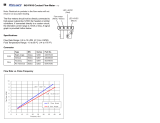
5
Set To
DCV
Set To
DCV
Voltage DC
Take measurements from the Molex Connector (either side)
If no power check molex connection at control board. If good replace control board.
2.5
5 VDC
2.5 VDC
To Red and
Black Wires
To White and
Black Wires
If not 2.5 VDC and you are reading 5 VDC through
the RED and BLACK wires, replace the Pusher Auger.
Diagram 3 - Encoder Voltage Test
Voltage DC

13
Copyright © 5/5/2016- Travis Industries Certified Factory Training Program
AGP™ Pellet Troubleshooting
5amp/125v Fuse
Encoder Molex
Diagram 4
STOVE
5amp/250v Fuse
Back Of Unit
INSERT
5amp/250v Fuse
Bottom of
Control Board

14
Copyright © 5/5/2016- Travis Industries Certified Factory Training Program
AGP™ Pellet Troubleshooting
Burn Platform
Igniter
Diagram 5 - Ignitor

15
Copyright © 5/5/2016- Travis Industries Certified Factory Training Program
AGP™ Pellet Troubleshooting

16
Copyright © 5/5/2016- Travis Industries Certified Factory Training Program
AGP™ Pellet Troubleshooting
AGP™ Pellet Insert
/