COMPANION 580.327112 Owner's manual
- Category
- Power generators
- Type
- Owner's manual
This manual is also suitable for

SE/AR_Owner's Manual
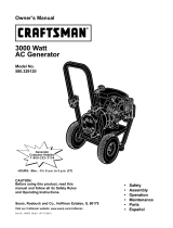
C OMPANION I
5000 Watt
A-C Generator
Model No.
580.327112
CAUTION: Before using this
product, read this manual and
follow all Safety Rules and
Operating Instructions.
HOURS: Mon.- Fri. 8 a.m. to 5 p.m. (CST)
SEARS, ROEBUCK and CO., Hoffman Estates, IL 60179 U.S.A.
Part No. B3051 .Draft 0 (7/23/98)

WARRANTY ............................... 2
SAFETY RULES ............................ 3
TROUBLESHOOTING ....................... 13
WIRING DIAGRAM ......................... 15
ASSEMBLY ................................ 4 REPLACEMENT PARTS .................. 16-22
OPERATION ......................... t.y_3_ _J EMISSIONS WARRANTY ................. 24-25
PRODUCT SPECIFICATIONS .......... {'__i' " ,.10 HOW TO ORDER PARTS ............ BACK PAGE
MAINTENANCE "_.":.":.":',._., ._. ,'T_:',. :_i 'Jl'O.:li
STORAGE -..; .:: .:-::-:-:::-:' ::":":_ .... _!!i:i;.12
'' L'iMi'TED ONE YEAR WARRANTY FOR COMPANION GENERATORS
SEARS warrants tO the Originalpurcl_aser that the alternator and engine for its portable generator will
be free from defects in materials or workmanship for the items and period set forth below from the
date of original purchase. This warranty is not transferable.
CONSUMER* COMMERCIAL*
Alternator 1 year 90 Days
Engine 1 year 90 Days
"NOTE: For the purpose of this warranty "Consumer Use" means personal residential householdand
emergency use by original purchaser, not to be used as a primary source of power. "Commercial Use"
means all other uses, includingrental, construction,commercial, and income producingpurposes. Once
a generator has experienced commercial use, it shall thereafter be considered a commercial use
generator for the purpose of this warranty.
During said warranty period, SEARS will, at its option, repair or replace any part which, upon
examination by SEARS, isfound to be defective under normal use and service**. Starting batteries
are not warranted by SEARS. All transportation costs under warranty, including returnto the factory if
necessary, are to be borne by the purchaser and prepaid by him. This warranty does not cover
normal maintenance and service and does not apply to a generator set, alternator or engine, or parts
which have been subjected to improper or unauthorized installation or alteration, misuse, negligence,
accident, overloading, overspeeding, improper maintenance, repair or storage so as, in SEARS's
judgment, to adversely affect its performance and reliability.
** NORMAL WEAR: As with all mechanical devices, engines need periodic parts service and
replacement to perform well. This warranty will not cover repair when normal use has exhausted the
life of a part or engine.
THERE IS NO OTHER EXPRESS WARRANTY. SEARS HEREBY DISCLAIMS ANY AND ALL
IMPLIED WARRANTIES, INCLUDING BUT NOT LIMITED TO THOSE OF MERCHANTABILITY AND
FITNESS FOR A PARTICULAR PURPOSE TO THE EXTENT PERMITTED BY LAW. THE
DURATION OF ANY IMPLIED WARRANTIES WHICH CANNOT BE DISCLAIMED IS LIMITED TO
THE TIME PERIOD AS SPECIFIED IN THE EXPRESS WARRANTY. LIABILITY FOR
CONSEQUENTIAL, INCIDENTAL, OR SPECIAL DAMAGES UNDER ANY AND ALL WARRANTIES
IS EXCLUDED. Some provinces do not allow limitationson how long an implied warranty lasts, or
the exclusion or limitationof incidental or consequential damages, so the abovelimitations or
exclusions may not apply to you. This warranty gives you specific legal rights and you may also have
other rights,which vary from state to state.
For service, see your nearest SEARS authorized warranty service facility. Warranty service can be
performed only by a SEARS authorized service facility. This warranty will not apply to service at any
other facility. At the time of requesting warranty service, evidence of original purchase date must be
)resented.
SEARS, ROEBUCK and CO., DI817WA, Hoffman Estates, IL 60179 U.S.A.
2

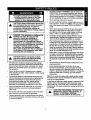
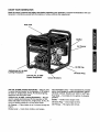
CAUTION: Always disconnect spark plug
wire and place the wire where it cannot
contact the spark plug. To prevent
accidental starting when setting up,
transporting, adjusting or making repairs
to your Generator.
A
DANGER: This generator is designed for
outdoor use only. Do not use this
generator inside any building or
enclosure including the generator
compartment of a recreational vehicle
(RV). Fire or an explosion may result. No
user performed modifications, including
venting of exhaust and/or cooling
ventilation, will eliminate the danger.
Also, allow at least two feet of clearance
on all sides of the generator even while
operating the unit outdoors.
CAUTION: Before using this product,
read this manual and follow all Safety
Rules and Operating Instructions.
• The generator produces dangerouslyhighvoltage
that can cause extremely hazardous electricalshock.
Avoidcontact with bare wires, terminals,etc. Never
permitany unqualified person to operate or service
the generator.
• Never handle any kindof electrical cordor device
while standingin water, while barefoot or while hands
or feet are wet.
• The National ElectricCode requiresthe frame and
externalelectricallyconductiveparts of generatorbe
properlyconnected to an approved earth ground.
Local electrical codes may also requireproper
groundingof the generator. Consultwith a local
electricianfor groundingrequirements inyour area.
• Use a ground fault circuitinterrupterin any damp or
highlyconductivearea (such as metal deckingor
steel work).
• Do not use any worn, bare, frayed or otherwisedam-
aged electrical cordsets with the generator.
• Operate generator only on level surfaces and where
it willnot be exposed to excessive moisture,dirt, dust
or corrosivevapors.
• Gasoline is highlyFLAMMABLE and itsvapors are
EXPLOSIVE. Do not permit smoking,open flames,
sparks or heat in the vicinitywhilehandlinggasoline.
Avoid spillinggasolineon a hot engine. Complywith
all laws regulatingstorage and handlingof gasoline.
• Never add fuel whileunit is running.
• Do not overfillthe fuel tank. Alwaysallow roomfor
fuel expansion. Iftank isoverfilled,fuel can overflow
ontoa hotengine and cause FIRE or an EXPLO-
SION.
• Never store generatorwith fuel in tank where gaso-
linevapors mightreach an openflame or spark or
pilotlight (as on a furnace, water heater or clothes
dryer). FIRE oran EXPLOSION mightresult.
• Generator exhaust gases contain DEADLY carbon
monoxidegas. Operate this equipmentonlyin the
open air where adequate ventilationisavailable.
• The engine-generatorrequiresan adequate flow of
coolingair for its continuedproperoperation. Never
operatethe unitinsideany roomor enclosurewhere
the free flow of cooling air intoand out of the unit
mightbe obstructed.Allowat least2 feet ofclearance
onall sidesofgenerator,evenwhileoperatingunitout-
doors,oryou coulddamage the unit.
• Never start, or stop,the engine-generatorwith electri-
cal loadsconnected to receptacleswith the connect-
ed devices tumed ON. Start the engine and let itsta-
bilizebefore connectingelectrical loads. Disconnect
all electricalloadsbefore shuttingdownthe genera-
tor.
• Do not insertany objectthrough coolingslots ofthe
engine-generator.
• Never operate generator (a) in rain;(b) in any
enclosed compartment;(c) if connected electrical
devices overheat;(d) ifelectrical outputis lost;(e) if
engine or generatorsparks; (f) if flames or smokeare
observed whileunitis running;(g) if unitvibrates
excessively.
Note: Ifyou equiptheenginewitha sparkarrestormuffler,
thesparkarrestormustbe maintainedineffectiveworking
orderbythe owner/operator.
In theState ofCalifomiaa sparkarrestoris requiredbylaw
(Section4442 oftheCaliforniaPublicResourcesCode).
Otherstatesmay havesimilarlaws. Federallawsapplyon
federal lands.The sparkarrestorpart numberfor thisunitis
pin34479A.
A
LOOK FOR THIS SYMBOL TO POINT OUT
IMPORTANT SAFETY PRECAUTIONS. IT
MEANS "ATTENTION!!! BECOME
ALERT!!! YOUR SAFETY IS INVOLVED."

Your A(3 generator requiressome assembly and is ready
for useafter it has been properly servicedwiththe rec-
ommended oil and fuel.
If you have any problems with the assembly of your
generator, please call the generator helpline at 1-800-
222-3136
Important: Any attemptto runthe engine beforeit has
been servicedwith the recommendedoilwill resultin an
engine failure.
TO REMOVE THE GENERATOR FROM
CARTON
• Set the cartonon a rigidflat surface with =THISSIDE
UP" arrows pointing upward.
Carefully open the top flapsof the shippingcarton.
• Cut down comers at one end of cartonfrom topto
bottomand lay that side of cartondownfiat.
• Remove all packing material, cartonfillers,etc.
• Remove the generatorfrom the shippingcarton.
CARTON CONTENTS
Check all contents. Ifany partsare missingor damaged,
call the Generator Helplineat 1-800-222-3136.
• The main unit
• Owner's manual
• Engine oil
CORD SETS AND CONNECTOR PLUGS
120 Volt Duplex Receptacle
Use only highquality, well-insulated, extensioncords with
the generator's120-volt duplex electricalreceptacles.
Each receptacle is protected againstoverloadby a push-
to-reset circuitbreaker. Use each receptacleto operate
120 volts,single phase 60 Hz, A C electricalloads requir-
ing upto 2400 watts (2.4 kW) at 20 amps of current.
A
CAUTION! Although each receptacle is
rated for 120 volts at 20 amps (2400 watts
or 2.4 kW), the generator is rated for a
total of 5000 watts. Powering loads that
exceed the wattage capacity of the
generator can damage it or cause serious
injuries. The total of loads with 120 volts
powered through these receptacles
should not exceed 20 amps.
Check the ratings ofall extension cords before you use
them. Extensioncord sets used shouldbe rated 125 volts
at 20 ac amps or greater for most electricaldevices.
Some devices, however, may not require thistypeof
extension cord. Check the owner's manuals of those
devices for the manufacturer's recommendations.
Keep extensioncordsas shortas possible,preferably
lessthan 15 feet long to prevent voltagedrop and possi-
ble overheating of wires.
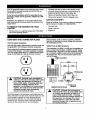
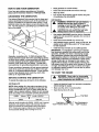
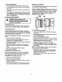
120/240 Volt, 20 AMP Receptacle
This receptacle isa NEMA L14-20R and is protected by a
push-to-reset circuitbreaker. A NEMA L14-20P mating
connector plug isrequired to usethis receptaclerecepta-
cle. Connect a suitable4-wire cordset tothe plugand to
the desired load. The cordset shouldbe rated for 250
volts at 30 amps.
Ire Cord Set
(Neutral)
Y(Hot)
X (Hot)
1201240 VOLTS PLUG (Green)
A
CAUTION! Although this receptacle is
rated for 240 volts at 20 amps (4800 watts
or 4.8 kwh, the generator is rated for a
total of 5000 watts (5.0 kW). Powering
loads that exceed the wattage capacity of
the generator can damage it or cause
serious injuries. Loads with 240 volts
powered through this receptacle should
not exceed 20 amps.

KNOW YOUR GENERATOR
Read the owner's manual and safety rules before operating your generator. Compare the illustrationswithyour
Generatorto familiarize yourselfwith the locationsof vadous controlsand adjustments.
Fuel Tank
120/240-Volt AC, 20 AMP
Locking Receptacle
/
120-Volt AC, 20 AMP
Duplex Receptacle
Circuit Breakers
Muffler
Air Cleaner
Oil Fill Cap
Oil Drain Plug
120 Volt, 20 AMP, Duplex Receptacles -- May be used
to supplyelectrical power forthe operationof 120 volts at
20 amps ac, single phase, 60 Hz, AC electricallighting,
appliance, tool and motorloads.
120/240 Volt, 20 AMP, Locking Receptacle -- May be
used to supplyelectrical power for the operationof 120
and/or 240 volts at 20 amps AC, single phase, 60 Hz, AC
electrical lighting,appliance, tool and motorloads.
Air Cleaner -- Filtersintake air as it isdrawnthroughthe
engine.
Choke Lever- Used when startinga coldengine.
Circuit Breakers (AC) -- Each receptacleis provided
with a circuitbreakerto protectthe generator against
electrical overload. Breakers are "pushto reset"type.
Fuel Tank -- Tank holds 5 U.S. gallonsofunleaded
gasoline.
Muffler -- Muffler lowersengine noise.
Oil Drain Plug -- Drainengine oilhere.
Oil Fill Cap -- Fill engine with oilhere.

HOW TO USE YOUR GENERATOR
Ifyou have any problemsoperating your Generator,
please call the Generator helplineat 1-800-222o3136.
GROUNDING THE GENERATOR.
The NationalElectricalCode requiresthat the frame and
extemal electricallyconductiveparts of this generator be
properlyconnectedto an approved earth ground. Local
electrical codes may also requireproper groundingof the
unit. For that purpose,a groundinglug is providedon the
base ofthe cradle.
• Place generator on a level surface.
• Clean area aroundoil filland remove oilfillcap
• Wipe cap dean.
• Pouroil intooilfillopening untiloilreaches the point
of overflowing. Do not overfill!
Add Gasoline
A
A
WARNING NEVER fill fuel tank indoors.
NEVER fill fuel tank when engine is
running or hot. DO NOT light a cigarette
or smoke when filling the fuel tank.
CAUTION: Do not overfill the fuel tank.
Always leave room for expansion.
Generally, connectinga No. 12 AWG (American Wire
Gauge) stranded copper wire to the groundinglugand to
an earth-drivencopper or brass groundingrod(electrode)
providesadequate protectionagainstelectrical shock.
However, localcodes may varywidely. Consultwith a
• local electricianfor groundingrequirements in yourarea.
Proper groundingof generatorwill help preventelectrical
shock in the event of a groundfault conditioninthe gen-
eratoror in connected electricaldevices. Proper ground-
ingalso helpsdissipatestatic electricity,whichoften
buildsup in ungroundeddevices.
BEFORE STARTING THE GENERATOR
To operatethe engine you willneed to do the following:
• Use regular UNLEADED gasoline withthe Generator
engine. Do not use premiumgasoline.Do not mixoil
with gasoline.
• Clean area aroundfuel fill cap, remove cap.
• Add unleaded regulargasoline,slowlyto fuel tank. Be
careful not to overfill.Allow about 1/4" oftank space
for fuel expansion.
• Installfuel cap and wipe up any spilledgasoline.
IMPORTANT: It isimportantto preventgum deposits
from forming in essentialfuel system partssuch as the
carburetor,fuel filter, fuel hose or tankduringstorage.
Also, experience indicatesthat alcohol-blendedfuels
(called gasohol, ethanolor methanol) can attractmoisture
which leads to separation and formation of acids during
storage.Acidic gas can damage the fuel systemof an
engine while in storage. To avoid engine problems,the
fuel system should be emptied before storageof 30 days
or longer. See "Storage"on page 12. Never useengine
or carburetor cleaner productsin the fuel tank or perma-
nent damage may occur.
TO START THE ENGINE
WARNING: Never start or stop engine I
with electrical devices plugged into the
I
panel receptacles and turned on.
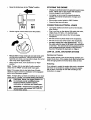
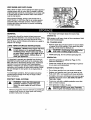
Add Engine Oil
NOTE: When adding oilto the engine crankcase in the
future, use onlyhigh quality detergent oil rated with API •
service classificationSF or SG or higher rated SAE 30 ,
weight. Use no specialadditives.Select the oil'sviscosity
grade accordingto your expectedoperating temperature.
I
colder -<----- 32°F _ warmer |
I
5W30 SAE 30
Although multi-viscosity oils (5W30, 10W30, etc.) improve
startingin coldweather, these multi-viscosity oilswill
resultin increased oil consumptionwhen used above
32°F. Check your engine oil level more frequently to
avoid possibledamage from runninglow on oil.
Unplug all electrical loads from generator receptacles
beforestarting the engine.
Make sure the unitisin a level position.
Open the fuel shut--offvalve.
J..d.._ FuelTank
Turn Clockwise to
"OFF" Position
6

• Move the choke lever to the "Choke" position.
I
RUN
t÷t
Set the engine controlswitchto the On position.
• Manual Start: Grasp starter grip and pull slowlyuntil
you feel some resistance.Then pullcord outwith
rapid fullarm stroke. Let rope retum slowly. Do not let
rope "snapback" againststarter.
• When engine starts, move choke lever to "Run"
position.
Note: If engine fails to startafter 3 pulls,move the
choke lever to "RUN" and pull starter ropeagain.
Note: If the engine fails to start afterthree (3) pulls,
check for proper oillevel in crankcase. Unitis equipped
with a lowoil shutdownsystem.
Note: If engine fires, but does not continueto run, move
choke lever to "Choke" and repeat startinginstructions.
,_ CAUTION! Never run engine indoors or
in enclosed poorly ventilated areas.
Engine exhaust contains carbon
monoxide, an odorless and deadly gas.
,_ WARNING! Temperature of muffler and
nearby areas may exceed 150°F (65°C).
Avoid these areas.
STOPPING THE ENGINE
• Unplug all electrical loadsfrom generatorpanel recep-
tacles. Never start or stop engine with electrical
devices plugged inand turned on.
• Let engine run at no-loadfor several minutesto
stabilizethe internaltemperatures of engine and
generator.
° Move engine controlswitchto "Off" Position.
° Closethe fuel shut-off valve
CONNECTING ELECTRICAL LOADS
• Let engine stabilizeand warm up for a few minutes
after starting.
• Plug in and turn on the desired 120 and/or 240 volts,
single phase, 60 Hertz, A C electrical loads.
• Do not connect 240 volts to the 120 volt duplex
receptacles
• Do not connect 3-phase loads to the receptacles.
• Do not connect any 50Hz loads to the receptacles.
• DO NOT OVERLOAD THE GENERATOR. Add up
the rated watts (or amps) of all loads tobe connected
at one time. This total shouldnot be greaterthan the
rated wattage/amperage capacityof the generator.
See Don't Overload the Generator on Page 9.
LOW OIL LEVEL SHUTDOWN SYSTEM
Sensing Low Pressure
If the system sensesa low oil levelduring operation,the
engine shuts down. Ifthe engine shuts downby itselfand
it has enough gasolinein the fuel tank, checkoil level.
Restarting
If you attempt to restartthe engine after such a shutdown
and have not corrected the engine oil level,the engine
will not start. Check the oil and refill accordingto the
instructionson page 7.
7

DON'T OVERLOAD THE GENERATOR ..
Overloadinga generator in excess of its rated wattage
capacity can resultin damage to the generator and to
connected electricaldevices. Observe the following, to
preventoverloadingthe unit:
, Add up the total wattage of all electricaldevices to be
connected at one time. This total should NOT be
greater than the generator's wattage capacity.
* The rated wattage of lights can be taken from light
bulbs. The rated wattage of tools, appliances and
motors can usually be found on a data plate or decal
affixed to the device.
• If the appliance, toolor motordoes not give wattage,
multiply volts times ampere ratingto determinewatts
(voltsx amps = watts).
Some electricmotors,such as inductiontypes,
requireabouttwoand a half times more watts of
powerfor startingthan for running. This surge of
powerlastsonlya few secondswhen startingsuch
motors. Make sure you allowfor this highstarting
wattage when selectingelectricaldevicesto connect
to your generator. First,figurethe watts neededto
start the largestmotor. Add to that figure the running
watts of all other connectedloads.
The Wattage Reference Guide below is provided to
assist you in determininghow many items your generator
can operate at one time.
WATTAGE REFERENCE GUIDE
Electrical Device Running
Watts
*Air Conditioner (12,000 Btu) ....................... 1700
Battery Charger (20 amp) .............................. 500
Belt Sander (3") ........................................... 1000
Chain Saw .................................................... 1200
Circular Saw (6-12/") ........................ 800 to 1000
Coffee Maker ............................................... 1000
*Compressor (1 HP) .................................... 2000
*Compressor (3/4 HP) ................................. 1800
*Compressor (1/2 HP) ................................. 1400
Curling Iron .................................................... 700
*Freezer ......................................................... 500
Disc Sander (9") ........................................... 1200
Edge Trimmer ................................................ 500
Electric Nail Gun .......................................... 1200
Electric Range (one element) ...................... 1500
Electric Skillet ............................................... 1250
*Furnace Fan (1/3 HP) ................................. 1200
Hair Dryer ..................................................... 1200
Hand Drill (1") .............................................. 1100
Hand Drill (1/2") ................................ 750 to 1000
Hand Drill (3/8") ............................................. 500
Hand Drill (1/4") ............................................. 250
Hedge Trimmer .............................................. 450
Electrical Device Running
Watts
Impact Wrench ................................................ 500
*Jet Pump ...................................................... 800
Lawn Mower ................................................. 1200
Light Bulb ....................................................... 100
Microwave Oven ............................................ 700
*Milk Cooler .................................................. 1100
Oil Burner on Furnace ................................... 300
Oil Fired Space Heater (140,000 Btu) ........... 400
Oil Fired Space Heater (85,000 Btu) ............. 225
Oil Fired Space Heater (30,000 Btu) ............. 150
*Paint Sprayer, Airless (1/3 HP) .................... 600
Paint Sprayer, Airless (handheld) .................. 150
Radio .................................................... 50 to 200
*Refrigerator ................................................... 600
Slow Cooker ................................................... 200
*Submersible Pump (1-1/2 HP) .................... 2800
*Submersible Pump (1 HP) .......................... 2000
*Submersible Pump (1/2 HP) ....................... 1500
Sump Pump .................................................. 600
*Table Saw (10") ............................. 1750 to 2000
Television ............................................ 200 to 500
Weed Trimmer ............................................... 500
* Allow 2-1/2 times the listed watts for starting
these devices.

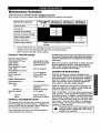
Maintenance Schedule
Follow the hourly or calendar intervals, whichever occurs first.
More frequent service is required when operating in adverse conditions noted below.
Maintenance Operation
Check oil level
Change oil_:
Service air pre-cleaner
Service air cleaner cartridge
Clean coolingsystem
Replace spark plug
Prepare unit for storage
Every5 Hours
or Ually
X
25 Hours or 50 Hours or 100 Hours or
Every Season Every Season Every Season
Generator Specifications
Rated Maximum Power ......... 5000 Watts (5.0 kW)
Surge Power ......... ....... 6250 Watts (6.25 kW)
Rated Voltage ............... 120/240 Volts AC
Rated MaximumCurrent
at 240 volts ................. 20.8 AC Amperes
Rated MaximumCurrent
at 120 Volts ................ 41.7 AC Amperes
Rated Frequency ............ 60 Hz at 3600 rpm
Phase ..................... Single Phase
Engine Specifications
Rated Horsepower ........... 10 at 3600 rpm
Spark Plug
Type: ................ Champion RC14YC or
Equivalent
Set Gap To: ........... 0.030inch (0.76mm)
Prepare unitfor storage if its to remain idlefor more than
30 days
Change oil after first 5 hours of operationthen after every 25 hours or every season.
" Change oil sooner when operating under heavy load or in high temperatures.
** Clean more often under dirty or dusty conditions.
PRODUCT SPECIFICATIONS
All adjustments in the Service and Adjustmentssectionof
this manual should bemade at least once each season.
Followthe requirementsinthe "Maintenance Schedule"
chartabove.
Note: Once a year you shouldclean or replace the spark
plugand replace the air filter. A new spark plug and
clean air filter assure properfuel-air mixtureand help
your engine runbetter and last longer.
GENERATOR MAINTENANCE
Generator maintenance consistsof keeping the unit
clean and dry. Operate and store the unitin a clean dry
environmentwhere itwillnot be exposedto excessive
dust,dirt, moistureor any corrosivevapors. Coolingair
slots in the generator mustnot become cloggedwith
snow, leaves, or any otherforeign material.
Check the cleanlinessof the generator frequently and
clean when dust,dirt, oil, moistureor otherforeign sub-
stances are visibleon itsexterior surface.
Gasoline Capacity ............ 5 U.S. gallons
Oil
Summer ............. SAE 30 (10W-30)
Winter .............. SAE 5W-20 or 5W-30
GENERAL RECOMMENDATIONS
The warranty ofthe Generator does not cover items that
have been subjected to operator abuse or negligence. To
receive full value from the warranty, operator must main-
tain Generator as instructed in this manual.
Some adjustments will need to be made periodically to
properly maintain your Generator.
Note: We DO NOT recommend using a garden hose to
clean generator. Water can enter the engine fuel system
and cause problems. In addition,ifwater enters the gen-
eratorthroughcoolingair slots, some of the water willbe
retained in voidsand cracksofthe rotorand stator wind-
ing insulation. Water and dirt buildup on the generator
internalwindingswilleventually decrease the insulation
resistanceofthese windings.
A AUTION: Never Insert any object or tool I
through the air cooling slots, even if the
!
engine is not running.
X
X

Toclean.theGenerator- ....
• Use a damp clotht0 Wipeexterior surfacesClean.
• A soft, bristlebrushmay be used to loosen caked on
dirt, oil, etc.
• A vacuum cleaner may be used to pickup loosedirt
and debris.
Low pressure air (not to exceed 25 psi) may be used
to blow away dirt. Inspect cooling air slots and open-
ings on the generator. These openings must be kept
clean and unobstructed.
ENGINE MAINTENANCE
A
DANGER: When working on the
generator ALWAYS disconnect spark
plug wire from spark plug and keep it
away from spark plug.
Checking Oil Level
Oil level shouldbe checked priorto each use or at least
every 5 hours of operation. Keep oillevel maintained.
Changing Engine Oil
To
Change oilafter first 5 hours of operation.Change oil
every25 hoursthereafter. If you are usingyour generator •
under extremely dirtyor dusty conditions,or in extremely
hot weather, change oil more often. •
Change oilwhile engine isstillwarm from running,as fol-
lows:
• Clean area around oil drain plug.
• Remove oildrain plug and oil fill plug and drain 0il
completely intoa suitable container.
• When oil has completely drained, Install oildrain plug
and tightensecurely.
• Fill oil sumpwith recommended oil. (See "Before
Startingthe Engine" on page 7 for oil recommenda-
tions)
• Install the oil fill plug and tighten securely.
• Wipe up any spilled oil.
CLEAN/REPLACE SPARK PLUG
Change the spark plug every 100 hoursof operation or
once each year, whichever comes first. This willhelp
your engine to start easier and run better. See
"Specifications" for proper spark plug.
• Clean area around spark plug.
• Remove and inspectspark plug.
• Replace spark plug if electrodes are pitted, burnedor
porcelain iscracked.
• Check electrode gap with wire feeler gauge and set
spark plug gap to 0.030 inch (0.76ram) if necessary.
" SERVICE AIR.... CLEANER"'_
Your engine willnot run properlyand may be damaged if
you run itusing a dirtyair cleaner.
Clean or replacethe foam pre-cleaner every 25 hours of
operation. Service cartridgeevery 100 hoursof operation
or once a year, whichevercomes first.Clean or replace
more often if operatingunder dustyordirtyconditions.
Replacements are availableat your localSears
Authorized Service Center.
service foam pre-cleaner:
The cover is attachedto the air cleaner housingby
two screws.
Carefullyremove air cleaner assemblyfrom insideof
cover and disassemble.
• Wash in liquiddetergentand water.
• Squeeze (don'ttwist) pre-cleaner in a clean, dry cloth.
• Saturate pre-cleanerin engine oil. Squeeze in a clean
absorbentclothto remove all excess oil.
• Replace pre-cleaner ifvery dirtyor damaged.
• To service cartridge, clean bytappinggentlyon a
flat surface. Replace ifvery dirtyor damaged. Do not
oil cartridge.
Note: Do not use petroleumsolventssuch as kerosene,
or pressurizedair to clean cartridge.
• Reassemble retaineron pre-cleaner and cartridge
(screen side of pre-cleanertoward cartridgepleats).
Install this assembly in cover.
• Insert tabs on cover into slots in base. Tighten cover
screws securely.
10

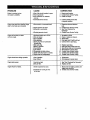
KEEP ENGINE AND PARTSCLEAN
With a brushor cloth, remove debris from debrisguard or
rotatingscreen dailyor more often ifneeded to prevent
engine damage caused by overheating.Do not clean with
a forceful spray of water because water couldcontami-
natethe fuel system.
Keep governor linkage, springs, and controlsfree of
debris.Debris or chaff may clogthe air coolingsystem,
especiallyafter prolonged operation.Remove blower
housingand clean area shown to preventoverheating
and engine damage.
CLEAN
OUT
DEBRIS
AND
CHAFF
GENERAL
The generator should be started at leastonce every
seven days and allowed to run at least 30 minutes. If this
cannotbe done and you must store the unitfor more
than 30 days, use the following informationas a guide to
prepare itfor storage.
LONG TERM STORAGE INSTRUCTIONS
A
WARNING: NEVER store engine with fuel
in tank indoors or in enclosed, poorly
ventilated areas where fumes may reach
an open flame, spark or pilot light as on a
furnace, water heater, clothes dryer or
other gas appliance.
It is importantto prevent gum depositsfrom formingin
essentialfuel system parts such as the carburetor,fuel
filter, fuel hose or tank during storage. Also, experience
indicatesthat alcohol-blendedfuels (calledgasohol,
ethanol or methanol) can attractmoisturewhichleads to
separationand formation ofacids duringstorage. Acidic
gas can damage the fuel system of an engine while in
storage.
To avoid engine problems, the fuel system shouldbe
emptied before storage of 30 days or longer. Follow
these instructions:
PROTECT FUEL SYSTEM
A
WARNING: Drain fuel into approved
container outdoors, away from open
flame. Be sure engine is cool. Do not
smoke.
• Remove all gasoline from the fuel tank to prevent gum
deposits from forming on these parts and causing
possible malfunction of engine.
• Run engine until engine stops from lackof fuel.
CHANGE OIL
While engine isstill warm, drain oilfrom crankcase. Refill
with recommended grade.
OIL CYLINDER BORE
• Remove spark plug and pour about 1/2 ounce (15ml)
ofengine oilintothe cylinder. Cover spark plug hole
with rag.Crank slowlyto distributeoil.
IA CAUTION' Av°id spray fr°m spark plug I
hole when cranking engine slowly.
• Installspark plug. Do not connectspark piug wire.
GENERATOR:
• Clean the generator as outlined on Page 10 ("To
Clean the Generator").
• Check that cooling air slots and openingson genera-
tor are open and unobstructed.
OTHER STORAGE TIPS:
• Do notstore gasoline from one season to another.
• Replace yourgasoline can if yourcan startsto rust.
Rust and/or dirtin yourgasolinewill cause problems.
• If possible,store yourunitindoors and cover itto give
protectionfrom dust and dirt. BE SURE TO EMPTY
THE FUEL TANK.
Cover your unit with a suitable protective coverthat
does not retain moisture.
• Store generator in clean, dry area.
I A DANGER:NEVERcoveryourGenerator i
while engine and exhaust area are warm.
I]

PROBLEM
Engineisrunning,butno
ACoutputisavailable.
Enginerunsgoodat no-loadbut "bogs
down"whenloadsare connected
Enginewillnotstart;or starts
andrunsrough.
CAUSE
1.Oneofthecircuitbreakersisopen.
2.Faultingenerator.
3.Poorconnectionordefective
cordseL
4.connecteddeviceisbad.
1.Shortcircuitina connectedload.
2.Enginespeedistooslow.
3.Generatorisoverloaded.
4.Shortedgeneratorcircuit.
1.Run/StopSwitchsettoSTOP.
2.Dirtyaircleaner
3.Outofgasoline.
4.Stalegasoline.
5.Sparkplugwirenotconnected
tosparkplug.
6.Badsparkplug.
7.Waterin gasoline.
8.overchoking.
9.Lowoillevel
10.Excessivelyrichfuelmixture.
11.Intakevalvestuckopenor closed.
12.Enginehaslostcompression.
CORRECTION
1. Resetcircuitbreaker.
2. ContactSearsServiceFacility.
3. Checkandrepair.
4. Connectanotherdevicethat
is ingoodcondition.
1. Disconnectshortedelectrical
load.
2. ContactSearsServiceFacility.
3. See=Don_Overloadthe
Generator"
4. ContactSearsServiceFacility.
1. Setswitchto RUN.
2. Cleanor replaceaircleaner.
3. RIIfueltank.
4. Draingastank;fillwithfreshfuel.
5. Connectwiretosparkplug.
6. Replacesparkplug.
7. Draingastank;fillwithfreshfuel.
8. Openchokefully andcrankengine.
9. RIIcrankcasetoproperlevel.
10. ContactSearsServiceFacility.
11. ContactSearsServiceFacility.
12. ContactSearsServiceFacility.
Engineshutsdownduringoperation 1.Outof gasoline. 1. Fillfueltank.
2iow oil level. 2. Fillcrankcaseto properlevel.
Enginelackspower. 1.Loadistoohigh. 1. See=Don'tOverloadtheGenerator"
2.Dirtyairfilter. 2. Replaceairfilter.
Engine=hunts"or falters. 1.
.
1.Chokeisopenedtoosoon.
2.Carburetorisrunningtoorich
ortoolean.
Movechoketohalfwaypositionuntil
enginerunssmoothly.
ContactSearsServiceFacility.
]2

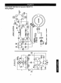
CRAFTSMAN 5000 Watt AC Generator 580.327112
Wiring Diagram
r_-
_L_ i
_d _/ Ii
I_ n,'o
o _glll II II
_________J
,_ r U L_-_
÷ I
cJ
<{
o
13

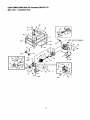
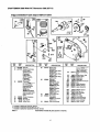
CRAFTSMAN 5000 Watt AC Generator 580,327112
Main Unit -- Exploded View
44 _ 66
59
• X " (STOP SVITCH TERMINAL)
900
38= tO,,
2
51 55
13
14
15
II
25
21
26
-36 TO • A •
22
35
49
14

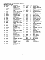
CRAFTSMAN 5000 Watt AC Generator 580.327112
Main Unit- Parts List
ITEM PART NO. Q_. DESCRIPTION
900 91011 1 ENGINE, Briggs &
Stratton 10 Hp
2 91020B 1 ASSEMBLY, Cradle
4 143-53621 1 WIRE, Ground
5 86292 1 CAPSCREW, #10 Self
Driller
6 75475 4 SCREW, M4-0.7 x 10ram
7 70642 2 MOUNT, Vibration
8 22129 8 WASHER, M8 Lock
10 38150 4 WASHER, No. 8 Flat
11 93585J 1 ASSEMBLY, Stator
12 66365G 1 HOUSING, Engine
Adapter
13 91844 1 ASSEMBLY, Rotor
14 65791 1 BEARING, Ball
15 47480 1 BOLT, Rotor 5/16"-24 x 7"
16 81917 1 PIN, M4 x 10 Roll
19 86308C 4 BOLT, Stator M6-1.00 x
130ram
20 22264 4 WASHER, No. 8 Lock
21 66849 2 SCREW, M5- .80 x 16ram
Taptite
22 86494 1 SCREW, M6 x 16mm
Wing
23 68759 1 RECEPTACLE, 120Volts
AC, 20AMP
24 94396B 1 BREAKER, Circuit-
20AMP
25 95600 1 PANEL, Control Sheet
Metal
26 91825 1 ASSEM, Brush & Bridge
Rectifier
27 67451 1 WASHER, Flat (Special)
28 23365 4 WASHER, No.8
Shakeproof
29 51715 4 NUT, M4-0.7 Hex
30 74908 4 SCREW, M5- 0.80 x
10ram
31 26850 2 WASHER, Shakeproof -
1/4"
32 84242 2 GROMMET, Rear Bearing
Carrier
33 86307 4 CAPSCREW, Hx Hd.-
5116"x 3/4"
34 67022 1 GROMMET, Bearing
Carrier
35 52858 6 NUT, M8-1.25 Hex
36 22769 1 WASHER, No. 10
Shakeproof
ITEM PAFITNO. QTY. DESCRIPTION
37 22145 2 WASHER, M8 Flat
38 68867 1 OUTLET, 120/240 Volt -
Twistlock
39 76222 2 SCREW, Pan Head-M8 x
40ram
40 48031C 2 CLAMP, 1/4" Hose
41 83465 4 GROMMET, Mounting
Tank
44 78831B 4 CAPSCW., Hx Hd.-M6-
1.0 x 60mm
46 90878 1 CAP, Fuel Tank
47 82857 2 MOUNT, Vibration
48 25244 2 NUT, 5/16" - 18 Hex
49 66825C 1 BEARING, Rear Carder
50 77374 1 TANK, Fuel
51 78299 1 BUSHING, Plastic Tank
52 80270 1 VALVE, Plastic Tank
53 77395 4 NUT, M6 Hex Lock
54 78951 1 SHIELD, Heat
55 56892 2 SCREW, Crimptite #10-24
x 3/8"
56 88977 1 SWITCH, Low Oil Shut-
Down (LOS)
57 91841 1 GASKET
58 91842 1 WIRE, Low Oil Shut-
Down
59 32713 2 SCREW, No. 10-32 x 3/4"
Taptite
60 22471 .... 2 NUT, No. 8-32
61 23365 1 WASHER, No. 8
Shakeproof
62 B3050 1 DECAL, Panel Cradle
63 98247 1 DECAL, Control Panel
64 94396A 1 BREAKER, Circuit 15
AMP
65 92982 1 DECAL, Danger
66 93826 1 DECAL, Operating
Instructions
Parts Not Illusbated
B3051 1 Owner'sManual
B3061 2 2007_EngineOil
Optional Accessories Not Illustrated
09-32684 Wheel I_t
O9-32688 CordWrap I_t
O9-32686 120/240V20A Rug
]5

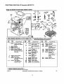
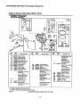
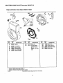
CRAFTSMAN 5000 Watt AC Generator 580.327112
Briggsand Stratton4 Cycle Engine19G412-1129-E1
z
3O6
7
552
10
I 1058 OWNER'S MANUAL J[ 1019 LABEL KIT I 9r REQUIRESSPECIALTOOLS TOINSTALL.
SEE REPAIR INSTRUCTION MANUAL.
REF. PART
NO. NO. DESCRIPTION
495631 Cylinder Assembly
(Includes OIL GARD®
Cover)
495657 Bushing
*391085 Seal-Oil
214347 Head-Cylinder
_272163 Gasket-Cylinder Hd.
495736 Breather Assembly
(Used After Code Date
95010100).
2
3
5
7
8
REF. PART
NO. NO. DESCRIPTION
13 94565 Screw-Cylinder Head
(3-9/16" Long)
13A 94733 Stud-Cylinder Head
Used in Position # 5 &
#6.
14 93723 Screw-Cylinder Head
(3" Long)
15 94239 Plug-Oil Drain
33 390419 Valve-Exhaust
(Indudes Fief. 42)
34 261055 Valve-Intake
35 65906 Spring--Valve
(Intake)
36 26828 Spring-Valve
(Exhaust)
40 221596 Retainer-Valve
41 292260 Retainer-Valve
42 494553 Keeper-Valve
306 496797 Shield--Cylinder
REF. PART
NO. NO. DESCRIPTION
337 496018
354A 94726
383 89838
529 281367
552 491986
635 66538
869 211661
871 261961
1019 491181
1058 272848
307 94386 Screw-Sell' Tapping
308 225055 Cover-Cylinder Head
9 *27803 Gasket-Breather
10 94621 Scfew-Sem
11 280225 Tube-Breather
(Used After Code Date
95010100).
11A 231900 Tube-Breather
(Used Before Code
Date 94111100).
13
5
Plug-Spark
Nut-Hex.
Wrench-Spark Plug
Grommet
(Used Before Code
Date 94111100).
Bushing--Gov. Crank
Boot-Spark Plug
Seat-Valve
Bushing-Guide
(Exhaust)
Note
231218 Bushing-
Guide
(Intake)
Label Kit
Owner's Manual
, Included in Gasket Set-Part No. 497070.
• Included in Carburetor Kit-See Rel. No. 121.
4, Included in Carburetor Gasket Set-Part No. 497069.
0432-2
Assemblies include all parts shown in frames.
25
]5

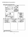
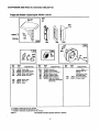
CRAFTSMAN 5000 Watt AC Generator 580.327112
Briggsand Stratton4 CycleEngine19G412-1129-E1
592
26
230
12
219
_:_186
3
f If'_\\
REF. PART REF. PART REF. PART
NO. NO. DESCRIPTION NO. NO. DESCRIPTION NO. NO. DESCRIPTION
25 3916733 *391086
12 *271701
16 495832
18 496984
19 295964
21 66768
22 93585
Seal-Oil
Gasket-Crankcase
(.015" Thick)
,27876 Gasket-
Crankcase
(.005" Thick)
,27877 Gasket-
Crankcase
(.009" Thick)
Crankshaft
Note
For "13ruingGear
Retaining Device.
Order Part No.
94388 Key.
495790 Crankshaft
Used on Type No(s).
0068, 0129, 0131,
0169.
Cover-Crankcase
Bushing
Plug-Oil Fill
Screw-Sem
26 393881
27 68546
28 295840
29 390401
Piston Assy.
(Standard)
391674 Piston Assy.
(.010" O.S.)
391675 Piston Assy.
(.02o-o.s.)
391676 Piston Assy.
(.030" O.S.)
Ring Set
(Standard)
299743 Ring Set
(Std.. Chrome)
393882 Ring Set
(.OlO-O.S.)
393883 Ring Set
(.020" O.S.)
393884 Ring Set
(.030"O.S.)
Lock-Piston Pin
Pin-Piston
(Standard)
295841 Pin-Piston
(.005"O.S.)
Rod-Connecting
30 222113
32 94670
45 260933
46 211689
84 9'1488
186 67218
202 263049
219 497037
220 221551
227 496254
23O
232
562
592
614
616
623
624
741
94742
26302O
92613
231082
93306
496818
231520
497207
262479
Note
390773 Rod-Conn.
(.020" Undersize)
Dipper-Connecting
Rod
Screw-Conn. Rod
Tappet-Valve
Gear-Cam
Plug-Pipe
Connector-Fuel Line
Link
Gear--Governor
Washer-Thrust
Lever-Governor
WasHer-Thrust
Spring-Link
Bolt-Carriage
Nut-Hex.
Pin-Cotter
Crank-Governc¢
•Screw-Shoulder
Lever-Linkage
Gear-'13ming
* Included inGasket Set-Part No. 497070.
• Included in Carburetor Kit-See Ref. No. 121.
€ Included in Carburetor Gasket Set-Part No. 497069.
0432-3
Assemblies include all parts shown in frames.
17

CRAFTSMAN 5000 Watt AC Generator 580.327112
BriggsandStratton4 Cycle Engine 19G412-1129-E1
REQUIRES SPECIAL TOOLS
TO INSTALL. SEE REPAIR
INSTRUCTION MANUAL.
95 987
52
REF. PART
NO. NO. DESCRIPTION
51 e,,272708 Gasket-Intake
52 ,272707 Gasket-Intake
53 94778 Stud-Carb. Mtg.
93 t281346 Bushing-Shaft
95 e94098 Screw-Round Head
98 495800 Screw-Idle Adjust
104 t231789 Pin-Float Hinge
105 D231935 Valve-Needle
106 e231856 Seat-Inlet
108 224666 Valve-Choke
116 494383 Valve-Needle
123 94616 Screw-Torx®Hex.
125 497844 Carburetor
(Used After Code Date
94083100)o
Note
497164 Carburetor
(Used Before Code
Dale 94090100).
127 • Plug-Welch
(Sold in Kit Only)
130 224539 Valve-Throttle
131 497846 Shaft-Throttle
(Used After Code Date
94083100).
REEF. PART REF. PART
NO. NO. DESCRIPTION NO. NO. DESCRIPTION
497198 Nozzle-Carb.
(High Altitude)
Include(s):
281164 Washer
(Used Before Code
Date 94062400).
147 o497472 Jet-Pilot
133 494381 Roat-C_,buretor (Used After Code Date
137 o,281165 Gasket-Float Bowl 94072400).
138 e+281164 Washer Note
141 497160 Shaft-Choke e231794 Jet-Pilot
142 e497564 Nozzle-Carburetor
(Used Before Code
(Used Afler Code Date Date 94072500).
94062300). 164 214170 Manifold-Intake
Note
497848 Nozzle-Carb. 186A 493496 Elbow-Fuel Pipe
(High Altitude) 618 e262803 Spring
Include(s): 634 •2.81168 Seal-Choke Shaft
281164 Washer 955 94642 Screw-Bowl Mtg.
(Used After Code Date 965 94010 Nut-Hex.
94062300). 975 494379 Bowl-Float
987 e281166 Seal-Throttle Shaft
e497197 Nozzle-Carb.
(Used Before Code
Date 94062400).
* Included in Gasket Set-Part No. 497070.
• Included in Carburetor Kit-See Ref. No. 121.
. Included in Carburetor Gasket Set-Part No. 497069.
0432-4
Assemblies include all parts shown in frames.
]8

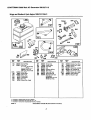
CRAFTSMAN 5000 Watt AC Generator 580.327112
BriggsandStratton4 CycleEngine19G412-1129-E1
63
@-
1
REF. PART
NO. NO. DESCRIPTION
55 393576 Housing-Rewind
Starter
56 295871 Pulley-Starter
57 490179 Swing-Rewind Starter
58 65884 Rope-Starter
(63"Long)
59 490653 Insert-Starter Handle
60 490652 Grip-Starter Rope
REF.
NO.
PART
NO. DESCRIPTION
63 260414 Spring-Ratchet
64 230543 Adopter-Ratchet
Spr_j
65 94128 Screw-Sem
66 399671 Clutch-StaRer
67 394897 Housing-Clutch
68 63770 Bali-Starter Clutch
REF. PART
NO. NO. DESCRIPTION
70 298799 Ratchet-Rewind
Starter
71 394506 Washer-Retainer
373 92987 Nut-Hex.
608 390391 Starter-Rewind
655 222598 Anchor-Spring
1018 490617 Spacer
* Included in Gasket Set-Part No. 497070.
• Included in Carburetor Kit-See Ref. No. 121.
• Included in Carburetor Gasket Set-Part No. 497069.
0432-5
Assemblies include all parts shown in frames.
]9

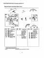
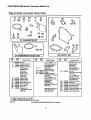
CRAFTSMAN 5000 Watt AC Generator 580.327112
Briggsand Stratton4 CycleEngine19G412-1129-E1
201
° 17sAi
•
209 209A
_271 269_'__ _
268
27O
RER PART REF. PART REF. PART
NO. NO. DESCRIPTION NO. NO. DESCRIPTION NO. NO. DESCRIPTION
75A 495659 Kit-Washer
98A 493280 Swing-Speed Adj.
165 94692 Nut-Wing
201 263051 Link
201A 262970 Link
209 263054 Spring--Governor
209A 260723 Spdng-Govemor
222 497076 Plate-Control
232A 262959 Spring-Link
258 94620 Screw-_elf Tapping
268 65616 Casing-Control Wire
(72" Long)
269 26633
Note
If Longer Casing is
Required, Specify
Length in Inches; if
Shorter Casing is
Needed, Cut to
Required Length.
W'_e-Control
(78" Long)
Note /
If Longer Wire is
Required. Specify
Length in Inches; if
Shorter Wire is
Needed, Cutto
Required Length.
270 63426 Locknut-Casing
271 290568 Lever-Control
333 492341 Armature-Magneto
334 94731 Screw-.Hex.
353 92791 Washer-I.,ock
354 90576 Nut-Hex.
356 491391 Wire--Stop
520 93722 Terminal
851 493880 Terminal-Cable
985 396525 Insulator
. Included in Gasket Set-Part No. 497070.
• Included in Carburetor Kit-See Ref. No. 121.
. Included in Carburetor Gasket Set-Part No. 497069.
0432-6 Assemblies include all parts shown in frames.
2O
Page is loading ...
Page is loading ...
Page is loading ...
Page is loading ...
Page is loading ...
Page is loading ...
Page is loading ...
Page is loading ...
-
 1
1
-
 2
2
-
 3
3
-
 4
4
-
 5
5
-
 6
6
-
 7
7
-
 8
8
-
 9
9
-
 10
10
-
 11
11
-
 12
12
-
 13
13
-
 14
14
-
 15
15
-
 16
16
-
 17
17
-
 18
18
-
 19
19
-
 20
20
-
 21
21
-
 22
22
-
 23
23
-
 24
24
-
 25
25
-
 26
26
-
 27
27
-
 28
28


COMPANION 580.327112 Owner's manual
- Category
- Power generators
- Type
- Owner's manual
- This manual is also suitable for
Ask a question and I''ll find the answer in the document
Finding information in a document is now easier with AI
Related papers
Other documents
-
Craftsman 580.329100 Owner's manual
-
Simplicity 01187-0 User manual
-
-
-
Generac SE10000 Owner's manual
-
 Champion Power Equipment 580.329120 Owner's manual
-
Harbor Freight Tools 212cc Quick start guide
-
-
-
