Page is loading ...

42, 54 & 72
ProBuilder MV
Owner’s Manual
WARNING: FIRE OR EXPLOSION HAZARD
Failure to follow safety warnings exactly could result in serious injury, death, or property damage.
- Do not store or use gasoline or other flammable vapors and liquids in the vicinity of this or any
other appliance.
- WHAT TO DO IF YOU SMELL GAS
• Do not try to light any appliance.
• Do not touch any electrical switch; do not use any phone in your building.
• Leave the building immediately
• Immediately call your gas supplier from a neighbor's phone. Follow the gas supplier's
instructions.
• If you cannot reach your gas supplier, call the fire department.
- Installation and service must be performed by a qualified installer, service agency or the gas supplier.
HOT GLASS WILL CAUSE
BURNS
DO NOT TOUCH GLASS
UNTIL COOLED
NEVER ALLOW CHILDREN
TO TOUCH GLASS
A barrier designed to reduce the risk of burns from
the hot viewing glass is provided with this appliance
and shall be installed for the protection of children
and other at-risk individuals.
Tested and Listed by
(42 MV) Report # 0028GF105S
(54 MV) Report # 0028GF105S
REV.002
(72 MV) Report # 0028GF105S-001
Omni-Test Laboratories, Inc.
Portland, Oregon
ANSI Z21.88-2016
CSA 2.33-2016
Operation
Maintenance
This appliance may be installed in an aftermarket, permanently located, manufactured home
(USA only) or mobile home, where not prohibited by local codes.
This appliance is only for use with the type of gas indicated on the rating plate. A conversion
kit is supplied with the appliance.
INSTALLER: Leave this manual with the appliance.
CONSUMER: Retain this manual for future reference.
Travis Industries, Inc. 12521 Harbour Reach Dr., Mukilteo, WA 98275 www.travisproducts.com
Copyright 2017, T.I. $10.00 10/28/20 100-01452

2 Table of Contents
© Travis Industries 10/28/20 - 1452 PB Lin MV Operation
Introduction
We welcome you as a new owner of a ProBuilder gas fireplace. This manual details operation and
maintenance of this fireplace. Please familiarize yourself with the Owner's Manual before operating your
heater and save the manual for future reference.
Important Information
No other ProBuilder gas fireplace has the same serial
number as yours. The serial number is on the listing
label that is chained to the gas control valve. This
serial number may be needed in case you require
service.
Model: 42 ProBuilder MV
54 ProBuilder MV
72 ProBuilder MV______
Serial Number:
Purchase Date:
Purchased From:
Register your warranty online at:
traviswarranty.com
Or, mail your warranty card to:
Travis Industries House of Fire
4800 Harbour Pointe Blvd. SW
Mukilteo, WA 98275
Save Your Bill of Sale.
To receive full warranty coverage, you will
need to show evidence of the date you
purchased your heater. Do not mail your Bill
of Sale to us.
We suggest that you attach your Bill of Sale
to this page so that you will have all the
information you need in one place should the
need for service or information occur.
Installation Warnings
Installation requirements are printed in the ProBuilder Installation Manual. All
requirements in the installation manual must be met.
Failure to follow all of the requirements may result in property damage, bodily injury,
or even death.
This heater must be installed by a qualified installer who has gone through a training
program for the installation of direct vent gas appliances.
This appliance must be installed in accordance with all local codes, if any; if not,
follow ANSI Z223.1 and NFPA 54(88). In Australia follow AS/NZS 5601.1.
In Manufactured or Mobile Homes must conform with Manufactured Home
Construction and Safety Standard, Title 24 CFR, Part 3280, or, when such a standard
is not applicable, the Standard for Manufactured Home Installations, ANSI/NCSBCS
A225.1. This appliance may be installed in Manufactured Housing only after the
home is site located.
The fireplace is designed to operate on natural gas, or propane (LP).
All exhaust gases must be vented outside the structure of the living-area.
Combustion air is drawn from outside the living-area structure.
Notify your insurance company before hooking up this fireplace.

Introduction 3
© Travis Industries 10/28/20 - 1452 PB Lin MV Operation
Table of Contents
Introduction ................................................... 2
Important Information ................................... 2
Installation Warnings .................................... 2
Table of Contents .......................................... 3
Features ......................................................... 3
Heating Specifications .................................. 3
Before You Begin .......................................... 6
Location of Controls ..................................... 6
Starting the Pilot ............................................ 7
Pilot Fuel Conservation Timer ..................... 8
Starting the Heater for the First Time .......... 8
Turning the Heater On and Off ..................... 9
Adjusting the Flame Height .......................... 9
Adjusting the Blower Speed (Optional) .... 10
Normal Operating Odors ............................ 10
Power Outages ............................................ 10
Glass Frame Removal and Installation .............. 11
Crushed Glass Installation ......................... 14
Maintaining Your Heater's Appearance .... 15
Cleaning The Glass .............................................. 15
Cleaning the Fireplace ......................................... 15
Yearly Service Procedure ........................... 16
Troubleshooting Table ............................... 17
Replacement Parts List .............................. 18
Wiring Diagram ........................................... 19
Optional Blower Wiring ...................................... 19
42 ProBuilder Safety Label ................................ 20
54 ProBuilder Safety Label ................................ 21
72 ProBuilder Safety Label ................................ 22
CONDITIONS & EXCLUSIONS ................... 23
IF WARRANTY SERVICE IS NEEDED: ...... 23
Index ............................................................. 24
Features
Works During Power Outages
Contemporary Look
Optional Blower for Heat Distribution
Optional Remote Thermostat
Standing Pilot
Variable-Rate Heat Output
Low Maintenance
Heating Specifications
Natural Gas Propane
42 ProBuilder
Approximate Heating Capacity (in square feet)* Up to 1,250 Up to 1,250
Maximum BTU Input Per Hour 25,000 25,000
54 ProBuilder
Approximate Heating Capacity (in square feet)* Up to 1,650 Up to 1,650
Maximum BTU Input Per Hour 33,000 33,000
72 ProBuilder
Approximate Heating Capacity (in square feet)* 2,250 2,250
Maximum BTU Input Per Hour 45,000 45,000
* Heating capacity will vary with floor plan, insulation, and outside temperature.

4 Safety Precautions
© Travis Industries 10/28/20 - 1452 PB Lin MV Operation
IF YOU SMELL GAS:
* Do not light any appliance
* Extinguish any open flame
* Do not touch any electrical switch or plug or unplug anything
* Open windows and vacate building
* Call gas supplier from neighbor's house, if not reached, call fire department
This unit must be installed by a qualified installer to prevent the possibility of an explosion.
Your dealer will know the requirements in your area and can inform you of those people
considered qualified. The room heater should be inspected and cleaned before use and at
least annually by a qualified service person. More frequent cleaning may be required due
to excessive lint from carpeting, bedding material, etc.
The instructions in this manual must be strictly adhered to. Do not use makeshift methods
or compromise in the installation. Improper installation will void the warranty and safety
listing.
This heater is either approved for natural gas (NG) or for propane (LP). Burning
the incorrect fuel will void the warranty and safety listing and may cause an
extreme safety hazard. Direct questions about the type of fuel used to your dealer.
Check for a label on the flame adjust knob on the gas control valve (this is the best
place to check). You may also check for a label on the gas control valve body.
Contact your local building
officials to obtain a permit and
information on any installation
restrictions or inspection
requirements in your area.
Notify your insurance company
of this heater as well.
If the flame becomes sooty, dark
orange in color, or extremely tall,
do not operate the heater. Call
your dealer and arrange for
proper servicing.
It is imperative that control
compartments, screens, or
circulating air passageways of
the heater be kept clean and
free of obstructions. These
areas provide the air necessary
for safe operation.
Do not operate the heater if it is
not operating properly in any
fashion or if you are uncertain.
Call your dealer for a full
explanation of your heater and
what to expect.
Do not store or use gasoline or
other flammable liquids in the
vicinity of this heater.
Do not operate if any portion of
the heater was submerged in
water or if any corrosion occurs.
Immediately call a qualified
service technician to inspect the
appliance and to replace any part
of the control system and any
gas control that has been under
water.
Ok
?
Gas

Safety Precautions 5
© Travis Industries 10/28/20 - 1452 PB Lin MV Operation
Do not place clothing or other
flammable items on or near the
heater. Because this heater can
be controlled by a thermostat
there is a possibility of the
heater turning on and igniting
any items placed on or near it.
Light the heater using the built-in
igniter. Do not use matches or
any other external device to light
your heater.
Allow the heater to cool before
carrying out any maintenance or
cleaning.
The viewing glass should be
opened only for conducting
service. Do not operate with
cracked, broken, or removed
glass.
Any safety screen or guard
removed for servicing must be
replaced prior to operating the
heater.
Never remove, replace, modify or
substitute any part of the heater
unless instructions are given in
this manual. All other work must
be done by a trained technician.
Don't modify or replace orifices.
Operate the heater according to
the instructions included in this
manual.
If the main burners do not start
correctly turn the gas off at the
gas control valve and call your
dealer for service.
Instruct everyone in the house
how to shut gas off to the
appliance and at the gas main
shutoff valve. The gas main
shutoff valve is usually next to
the gas meter or propane tank
and requires a wrench to shut off.
This unit is not for use with solid
fuel
Do not place anything inside the
firebox (except the crushed
glass).
If any component becomes
damaged, replace with Travis
Industries components.
Do not throw this manual away.
This manual has important
operating and maintenance
instructions that you will need at
a later time. Always follow the
instructions in this manual.
Children and adults should be
alerted to the hazards of high
surface temperature and should
stay away to avoid burns or
clothing ignition. Young children
should be supervised when they
are in the same room as the
heater.
Travis Industries, Inc. grants no
warranty, implied or stated, for
the installation or maintenance of
your heater, and assumes no
responsibility of any
consequential damage(s).
The viewing glass should be opened only for conducting service (or lighting the pilot on millivolt units).
Suggestions on how to limit the need to restart the pilot during the heating season can be found on page 8
This
Manual

6 Operation
© Travis Industries 10/28/20 - 1452 PB Lin MV Operation
Before You Begin
Read this entire manual before you use your new fireplace (especially the section "Safety
Precautions" on pages 4 & 5). Failure to follow the instructions may result in property damage, bodily
injury, or even death.
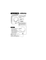
Location of Controls
There is a door on the lower portion of the screen assembly to provide access to the manual controls on
the fireplace. The door is held closed by two magnets. Open the door by gently pulling outward on the
upper portion of the lower trim.
On/Off Switch This control is used to turn the heater on and off.
Pilot Igniter The pilot igniter is used only to start the pilot. When pressed, it sends an
electrical charge to the pilot assembly. This creates a blue spark directly
next to the pilot, igniting the pilot flame.
Gas Control Knob This knob is used to control gas to the heater and for starting the pilot. There
are three positions, ON, OFF, & PILOT. The pointer to the left of the knob
indicates the position this knob is in.
Flame Adjust Knob This knob controls the flame height from low ("LO") to high ("HI"). The
pointer above the knob points to the position this knob is in.
Optional Remote Receiver The receiver is used in conjunction with the optional remote thermostat. It is
used to control the remote and replaces the on/off switch for direct operation.
Optional Blower Dial This dial controls the speed of the internal convection blower that pushes the
heated air into the room.
Optional Light Dial This dial controls the brightness of the optional accent lights (if applicable).
Pilot Igniter
On/Off Switch
Optional Blower Dial
Shutoff Valve
(accessible with
screen removed)
Rotate the Control Door Down to
Access Controls
Optional Remote Receiver
Gas Control Knob
Flame Adjust Knob
Optional Light Dial

Operation 7
© Travis Industries 10/28/20 - 1452 PB Lin MV Operation
Starting the Pilot
Remove the glass frame before starting the pilot.
The pilot flame is required to ignite the main
burners (it also plays a safety role). It should be
left on once lit. It will stay lit unless the gas
control valve is turned to "OFF" or if the burner
has not been lit in a 7 day period (see “Pilot Fuel
Conservation Timer” section on pg. 8).
However, the pilot will go out if the gas is shut
off, the propane tank runs out (or low) or if the
stove malfunctions. If the pilot turns off
frequently, call your dealer for information.
NOTE: Suggestions on how to limit the need to
restart the pilot during the heating
season can be found on page 8
To start the pilot follow the directions below:
WARNING:
When lighting or re-lighting the pilot, the
glass must be removed (see page 11).
a Remove the glass (see page 11 for details).
b Push the gas control knob in slightly and
turn it to the "OFF" position. The knob will
not turn from "ON" to "OFF" unless the knob
is depressed slightly. Wait five minutes to
let any gas that may have accumulated
inside the firebox escape. If you smell
leaking gas, follow the directions on the
cover "IF YOU SMELL GAS".
c Turn the gas control knob to the "PILOT"
position and press the knob in, this will allow
gas to flow to the pilot light. Press the
button on the pilot igniter repeatedly until
you see the pilot light.
WARNING:
If the pilot does not light after 15 seconds,
release the knob and call your dealer for
service. Do not attempt to light pilot until
service has been performed.
d Keep the gas control knob depressed for 30
seconds once it is lit.
e Release the gas control knob. If the pilot
goes out, repeat step C. If the pilot refuses
to stay lit, call your dealer for service. With
the pilot lit, proceed to step “f”.
f Replace the glass.
g Turn the gas control knob counter-clockwise
to "ON". The pilot is now lit and the heater
can be turned on and off.
30 seconds
PILOT
IGNITER
a
b
5 minutes
c
d
e
f
g
?

8 Operation
© Travis Industries 10/28/20 - 1452 PB Lin MV Operation
Pilot Fuel Conservation Timer
7 Day Pilot Shutoff Timer (MV Units)
This appliance is equipped with a 7 day pilot shutoff
timer. This timer helps conserve fuel and save money by
turning the pilot off when the appliance is not used for 7 days
(this timer is mandated in certain areas for conservation
purposes).
The appliance will function normally as long as the burner is
engaged within a 7 day window. Each time the burner is
turned on the 7 day timer resets. If the burner is not engaged
within the 7 day window, the pilot will automatically turn off to
conserve fuel. If the pilot is turned off, it will need to be manually re-lit.
To prevent the need to restart the pilot during the heating season, we have listed a few strategies below:
Option 1: Remember to periodically turn on the heater during the heating season
If you use your heater for supplemental heat, this may be the best solution. Set a specific time, once or
twice per week (e.g. 5pm on Tuesday & Friday) to turn the heater on for a few minutes. This will restart
the timer and prevent the need to restart the pilot.
Option 2: Install a thermostat
This will keep the room at a constant temperature and will, in most cases, keep the heater working
throughout the heating season. Light the pilot at the beginning of the heating season and set the
thermostat to the desired room temperature. As long as the outside temperatures does not rise
excessively, for seven days or more, the pilot will continue to operate.
Option 3: Use a programmable thermostat
A programmable thermostat may be set to turn on, once per week, to a high temperature for a short
time. This will reset the 7-day timer and allow the heater to operate without having to restart the pilot.
Starting the Heater for the First Time
Burn the heater at a high setting with the blower off for an extended period (up to 48 hours). This will
cure the painted surfaces. Fumes from the paint curing and oil burning off the steel will occur. This
is normal. We recommend opening a window to vent the room.
Condensation may appear on the glass each time you start the heater - this is normal.
Blue Flames will occur on the heater when it first comes on. After fifteen minutes the flames will turn
a more realistic yellow and orange color.

Operation 9
© Travis Industries 10/28/20 - 1452 PB Lin MV Operation
Turning the Heater On and Off
Do not place any combustible items on top of or directly in front of the heater, even temporarily. The
optional thermostat may start the heater causing a combustible item to ignite.
If the heater turns on and off frequently while using the thermostat, you may want to adjust the flame
height down until it produces just enough heat needed.
Adjusting the Flame Height
Your heater has an adjustable flame to tailor the look and heat output to your specific needs. It is
adjusted by turning the middle dial on the gas control valve.
O
F
F
O
N
ON/OFF SWITCH
Use this switch to turn the main
burner on and off manually.
A
fter the pilot has been started...
OPTIONAL REMOTE THERMOSTAT
See the instructions included with the remote
for details on operation.
°F
Flame Height
Adjustment Knob
Index Mark
Turn counter-clockwise to adjust the flame higher, clockwise to lower.

10 Operation
© Travis Industries 10/28/20 - 1452 PB Lin MV Operation
Adjusting the Blower Speed (Optional)
The optional blower helps transfer heat from the heater into the room. It will not turn on until the heater is
up to temperature (approximately 10 minutes after starting). See the illustration below for instructions on
adjusting the blower speed.
Normal Operating Odors
This appliance has several areas that reach high temperatures. Dust or other particles on these areas
may burn and create an odor. This is normal during start-up. You may notice the smell is more acute if
the appliance was left idle for a long period.
Power Outages
The heater will work if household current (AC power) is disconnected.

Maintenance 11
© Travis Industries 10/28/20 - 1452 PB Lin MV Operation
Glass Frame Removal and Installation
A barrier designed to reduce the risk of burns from the hot viewing glass is provided
with this appliance and shall be installed for the protection of children and other at-risk
individuals.
If the barrier becomes damaged, the barrier shall be replaced with the manufacturer’s
barrier for this appliance.
The appliance must be completely cool before removing the glass.
Do not strike or slam the glass.
Warning: Do not operate appliance with the glass front removed, cracked or broken.
Replacement of the glass should be done by a licensed or qualified service person.
Remove the screen-trim assembly by lifting the assembly up slightly and tilting it toward you. The
mounting hooks on the back of the assembly will disengage the fireplace. Set the assembly aside for
reinstallation.
NOTE: Opening the access door on the front of the assembly allows for an easy location to get a secure grip
on the assembly for removal
Replacement Barrier Part #
42 ProBuilder 250-04494
54 ProBuilder 250-04690
72 ProBuilder 250-04655
Top Corner
Bottom Corner
Bottom hook
engages this slot in
bracket
Top hook engages
this slot in bracket

12 Maintenance
© Travis Industries 10/28/20 - 1452 PB Lin MV Operation
Remove the glass frame following the directions below.
Replacement Glass Frame Part #
42 ProBuilder 250-04491
54 ProBuilder 250-04689
72 ProBuilder 250-04654
Open the latches holding the glass frame in place (start with
the bottom) - follow the directions shown to the right.
a
Lift the glass frame up and
pull it forward to remove.
b
Re-Attaching the Glass Frame:
a) Hang the glass frame on the firebox.
b) While holding in place, attach the upper latches
(follow the instructions to the right in reverse).
c) Lift the glass frame slightly and attach the lower latches.
NOTE: Make sure the glass frame is all the way in place - it should
be parallel with the front of the fireplace when installed.
NOTE:
You may need to lift
the glass frame
while re-attaching.
Glass
Top of
Firebox
Latch
Catch
(on glass frame)
Pliers may be used
NOTE: Make sure the glass frame is all the way in place – It should be parallel with the front of the
fireplace when installed.

Maintenance 13
© Travis Industries 10/28/20 - 1452 PB Lin MV Operation
The latch can come loose from glass frame anchor. This occurs when it is turned 1/4 turn when it
is disengaged. Follow the directions below to re-install the latch if it becomes loose.
Top of
Firebox
Hold the latch at an angle and insert it into the slot on the glass frame anchor.
NOTE: this slot may be at a
different angle than illustrate
d.
Note how the washer on the latch fits behind the flange on the
g
lass frame anchor.
Glass Frame
Anchor
O
nce fully inserted, turn the latch until it is upright.
Latch

14 Maintenance
© Travis Industries 10/28/20 - 1452 PB Lin MV Operation
Crushed Glass Installation
Do not allow the crushed glass to block the air slots or to become too thick (maximum 1
layer deep on the burner). Failure to properly install glass may lead to sooting and
improper burning.
If converting to LP (propane), convert the appliance prior to placing the crushed glass.
Install the crushed glass on the glass tray following the directions below.
Quantity of Crushed Glass
42 ProBuilder 5 lbs. (2.3 Kg)
54 ProBuilder 6 lbs. (2.7 Kg)
72 ProBuilder 8 lbs. (3.6 Kg)
1 Spread and even layer of crushed glass over the media tray and burner. The glass must be only 1
layer thick on the burner but can be 2 layers thick on the media tray. Make sure no glass is in the
pilot area indicated in the picture below.
Make sure the rear and end air channels are free of crushed glass. Use a screwdriver to clear this area.
Make sure the glass is only 1 layer deep on the burner.
No glass in
this area.
Only one layer
thick on burner

Maintenance 15
© Travis Industries 10/28/20 - 1452 PB Lin MV Operation
Maintaining Your Heater's Appearance
The appliance must be completely cool prior to conducting service.
Cleaning The Glass
The glass may be cleaned with a non-
abrasive cleaner. To clean the inside of
the glass, simply remove the glass frame,
place it on a non-scratching surface, and
clean the surface.
Cleaning the Fireplace
Use a duster to remove dust from the visible portions of the fireplace. Contact your dealer if you wish to
re-paint any surfaces. Heat-resistant stove-paint (with instructions) is available from your dealer.

16 Maintenance
© Travis Industries 10/28/20 - 1452 PB Lin MV Operation
Yearly Service Procedure
WARNING: Failure to inspect and maintain the stove may lead to improper combustion and a potentially
dangerous situation. We recommend the following procedures be done by a qualified
technician.
Shut off gas to the fireplace and let it cool for 15 minutes. Remove the glass. Inspect and operate the
pressure relief mechanism to verify relief mechanisms are free from obstruction to operate.
Clean glass window with a suitable fireplace glass cleaner. Abrasive cleaners must not be used. Be
careful not to scratch the glass when cleaning.
Vacuum and clean any debris in the firebox.
Check all accessible gas-carrying tubes, connections, pipes and other components for leaks.
Inspect the burner and firebox. Make sure the burner is not warped, cracked, or damaged. Check the
firebox and area around the pilot to make sure there is no damage. Inspect primary air openings for
blockage. If any problem is found, discontinue use and contact your dealer for service.
Inspect the area behind the access door; clean if necessary. Check the gas control valve and the gas
lines. If damage is found, discontinue use and contact your dealer for service. Clean the air channels,
ducts, and blower (if applicable)
Inspect vent and vent termination for sooting, obstructions, or damage. Make repairs as needed.
Remove any debris or vegetation near the vent termination. Contact your dealer if any sooting or
deterioration is found near the vent termination.
Turn the pilot flame on (MV units) or turn on the continuous pilot (GS units). It should touch
approximately 3/8" of the top of the flame sensor (see below). If it does not, contact your dealer.
Reinstall the glass assembly. If the glass is damaged, replace it. Make sure the gasket along the
perimeter of the glass contacts the face of the firebox and forms an air-tight seal. If it does not, re-align or
replace the gasket to ensure an air-tight seal.
Start the main burner. Inspect and ensure the lighting of the main burner occurs within 4 seconds of the
main gas valve opening.
Test the flame failure response time of the flame safety system. It must de-energize the safety shutoff in
no more than 30 seconds.
After 15 minutes the flames should be orange/yellow and not touch the top of the firebox. If the pilot or
main burners do not burn correctly, contact your dealer for service. Monitor blower operation
GS Pilot
MV Pilot

Maintenance 17
© Travis Industries 10/28/20 - 1452 PB Lin MV Operation
Troubleshooting Table
Problem: Possible Cause: Don't Call for Service
Until You:
Pilot Will Not Light
A gas shut off valve is turned off
The gas control knob isn't turned to "PILOT"
The valve control knob isn't pushed in
The igniter wasn't pressed repeatedly
No Propane in Tank
Check all gas shut off valves
See "Starting the Pilot Light" Step C
See "Starting the Pilot Light" Step C
See "Starting the Pilot Light" Step C
Check Tank Level
Main Burners Will
Not Start
The pilot light has gone out
The gas control valve is turned to "PILOT" or "OFF"
The ON/OFF switch is turned to "OFF"
The remote control is not working correctly
The thermostat is disconnected or set too low
See "Starting the Pilot Light"
See "Starting the Pilot Light"
Turn the ON/OFF switch to "ON"
See the remote control instructions
See "Thermostat Operation"
Optional Remote
Control Does Not
Work
The pilot light has gone out
The gas control valve is turned to "PILOT" or "OFF"
The ON/OFF switch is turned to "OFF"
The remote is too far away from the heater
The remote control receiver is turned "Off"
Remote or receiver batteries are dead
See "Starting the Pilot Light"
See "Starting the Pilot Light"
Turn the ON/OFF switch to "ON"
Use the remote closer to the heater
See the remote control instructions
See the remote control instructions
Heater Will Not
Distribute Heat
The heater is not up to temperature This is normal – allow 5 to 20 minutes for
heater to reach operating temperature.
Optional Blower
Does Not Turn On
The heater is not up to temperature
The heater is not getting electricity
The blower is set to off
The blower will turn on once the heater is
up to temperature (5 to 20 minutes).
Check the breaker switch.
Check the blower knob.
Pilot Goes Out
Intermittently
The gas supply has been shut off
Keep the gas supply turned on
Flames Are Too
Blue
The heater has just been started
Improper air shutter adjustment
This is normal - see "Starting the Heater
for the First Time"
Adjust Air Shutter - contact your dealer
Flames Are Too
Short (Under 6")
The flame height may be turned too low
Turn the flame height to "HI" -
See "Adjusting the Flame Height"
Thin Layer of Soot
Covers the Glass
The logs or coals are placed incorrectly
Improper air shutter adjustment
See "Log Set Installation"
Adjust Air Shutter - contact your dealer

18 Maintenance
© Travis Industries 10/28/20 - 1452 PB Lin MV Operation
Replacement Parts List
Caution: Use only Travis Industries replacement parts. Do not use substitute materials.
Warning: Do not operate appliance with the glass front removed, cracked, or broken. Replacement of
the glass should be done by a licensed or qualified service person.
GLASS w/FRAME (42 ProBuilder) 250-04491
GLASS w/FRAME (54 ProBuilder) 250-04689
GLASS w/FRAME (72 ProBuilder) 250-04654
SCREEN BARRIER, FRONT (42 ProBuilder) 250-04494
SCREEN BARRIER, FRONT (54 ProBuilder) 250-04690
SCREEN BARRIER, FRONT (72 ProBuilder) 250-04655
PILOT ASS'Y, 3-WAY PSE 250-04481
VALVE, NG w/MANUAL H/L 250-04377
VALVE REGULATOR, LP MAN HI-LO 250-00415
Contact your local Travis Industries Dealer for Replacement Parts

Maintenance 19
© Travis Industries 10/28/20 - 1452 PB Lin MV Operation
Wiring Diagram
Caution: Label all wires prior to disconnection when servicing controls. Wiring errors can cause
improper and dangerous operation.
Optional Blower Wiring

20 Safety Label
© Travis Industries 10/28/20 - 1452 PB Lin MV Operation
42 ProBuilder Safety Label
The safety (listing) label is attached to the operating tag (chained to the heater near the gas control
valve). A copy is shown below
/