Page is loading ...

LanRoamerPROf Tester/Analyzer
User's Guide
www.jdsu.com/hbn


Warning!
Do not attach to energized cables. The
LanRoamerPRO
™
may be damaged.
Caution!
Improperly crimped, damaged or un-
crimped plugs can damage the jacks on
the LanRoamerPRO
™
. Inspect plugs for
proper termination and crimping before
inserting into the tester. Contacts should
always be recessed into the plastic grooves
of the plug. Do not use with 6 position
plugs (RJ11) without an adapter.

1
Features
• Auto-on and auto-off when testing cables, just
plug both ends into tester!
• Two-line by 16-character full alphanumeric
LCD with icons for clear results
• Cable test results displayed in wire map format
with a message line for shorts and split pairs
• Tests for shorts, opens, miswires, reversals
and split pairs with remote connected
• Pre-test – One-ended testing for shorts,
opens and split pairs (no remote)
• Displays PASS icon and sounds beeper
(optional) for T568A/B passing cables
• Length measurement in feet or meters using
cable capacitance method
• Tone generator mode for use with tone
tracers
• Auto-off in any mode and low power
consumption for long battery life
• Snap-together case for easy storage of a
remote and convenient patch cable testing

2
Description
The LanRoamerPRO
™
has an LCD display and
four momentary buttons. One remote attaches
to the main unit for storage or patch cable
testing. The rubber end cap at the bottom is
the battery compartment cover.
The LanRoamerPRO
™
starts in an off condition
when cable testing with a remote. This yields
maximum battery life and takes advantage
of the fact that the auto-on feature effectively
synchronizes the test cycle to the cable being
connected for results in 2 seconds. The tester
powers on and testing begins automatically
when a connection from the main unit to the
remote is sensed. The tester will automatically
power off within 5 seconds of the cable being
disconnected.
Upon completion of the test, the wire map
display, ID and any faults are displayed. The
top line of numbers on the display represents
the connector pins on the main unit. The
second line of pin numbers is the connector
pin numbers of the remote, normally being the
same as the top line for a normal data cable. If
there is a miswire, the numbers on the second
line will indicate the pin numbers detected. If
no connection was detected for some of the
pins, the second line will be blank in those pin
locations. If a short is detected, the second
line will have a flashing “x” in that position and
the specific short condition displayed on the

3
third line. If a split pair is detected, those pin
positions on the second line will be flashing the
pin numbers detected from the remote and the
specific split condition displayed on the third
line. If there are multiple errors to display on
the third line, the messages are displayed in
sequence until all are displayed. The ID icon
will have a number directly below it indicating
the remote ID number.
The LanRoamerPRO
™
is powered on by
pressing any of the four buttons. The tester will
turn on in the last mode used before turning off.
There are four modes of operation as described
below. In any mode, pressing the MODE
button causes the mode select screen to be
displayed. The TURN OFF message is usually
the first one displayed. Subsequent presses
of the MODE button cycle through the other
modes. Pressing the SEL button causes the
currently displayed mode to be entered.
Test/Pre-test – If a remote is sensed, the
tester reverts to the power off cable test
described above (Test). If there is no remote,
the LanRoamerPRO
™
uses the length and
cable test capability to attempt to measure a
cable for shorts, opens and split pairs (Pre-
test). TEST and the current pair under test
icons being on indicate a test in progress. The
results are displayed as messages on the LCD.
Because a test can take up to about 5 seconds
to complete, the SEL button, which immediately

4
starts a new test, should be pressed whenever
a new cable is connected for pre-test. Partial
and erroneous results will be displayed until a
complete test cycle has been run on a cable.
Length – The length mode measures the
length of a cable by measuring its capacitance
and using the capacitance per unit length
(length constant) to calculate the length. The
length is displayed on the LCD along with the
current value of the length constant. The SEL
button changes the pair being measured in
a 1-2, 3-6, 4-5, 7-8 and auto-select sequence.
The pair number is displayed next to the length
except in auto-select mode. If a selected
pair has a fault, the fault replaces the length
reading on the LCD. In auto-select mode, the
tester automatically selects a pair without a
fault. The length constant is changed with the
up and down arrows. The CAL icon is on while
adjusting the constant. If network terminator
patterns are found in length mode, the tester
will display “T Ring Network??”, “xbase-
T Network?” or “Network?” (all four lines
terminated).
Tone – The tone mode generates audio tones
for use with tone tracers on all pairs, a selected
pair or a selected pin. The signal generated
on a pair has the signal on one pin and the
complement of the signal on the other pin of
the pair, yielding a nominal 10 volts peak-to-
peak across the pair. The SEL button selects

5
one of the four tone sounds provided. The up
and down arrows scroll through the pairs and
pins that have signal on them. All pins not
being driven are held at tester ground.
Setup – The setup mode is provided to set
user-selectable options. The beep-on-pass can
be turned on or off (default is on). The pass
criteria can be set for shielded or unshielded
cables (default is unshielded). The length and
length constant can be set for meters or feet
(default is feet). If the length units are changed,
the tester converts the currently set length
constant to the new units on exit of setup. The
up and down arrow buttons scroll through the
set-able options. The SEL button changes the
current setting to the other option. On exit, the
mode screen first offers to return to the last
mode used before entering setup.
The LanRoamerPRO
™
monitors for voltage
being present on the RJ jack when off, in
TEST/PRE-TEST mode or in LENGTH mode.
The “VOLTAGE!!” message appears on the
screen and the beeper sounds continuously
until the voltage is removed.

6
LanRoamerPRO
™
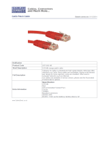
LCD Display
PASS FAIL CAL SETUP TEST
1 2 3 4 5 6 7 8 S
ID
Beeper
Off
Battery
Low
Main Unit Pin
Numbers
Alphanumeric
Characters
ID Number
Icon
(Remote ID
Displayed
Below It)
Adjusting Length Constant
Setup Mode
Cable Has
Faults
Test in
Progress
Cable Passed
T568A/B
Cable Shield
Indicator

7
Instructions for Use
LanRoamerPRO
™
powers off automatically
after 5 minutes of continuously testing a
cable when auto-on powered up the tester.
Disconnecting the cable restores normal
function. Most power-on modes will timeout
in about 18 minutes, except for tone, which is
about 2.4 hours. Be sure to install a battery if
using for the first time—see battery installation.
Cable Testing
To Test a Patch Cable (see “Caution!” on
page 1 about cables with bad plugs)
1) Plug one end of patch cable into main unit.
2) Plug other end of cable into remote unit.
3) The tester will power on immediately and
will indicate a test in progress by displaying
the TEST icon. It will be followed by map
results plus a PASS icon and a beep, if it
passed both the T568A/B standard and the
configured shield criteria.
4) Disconnect patch cable after test. The test
repeats every 5 seconds.

8
To Test Cable from One End
This can be done immediately after termination
of one end of the cable, because no connector
or remote is required at the other end of the
cable. Attach a remote after the pre-test and
you are ready for a full test when the other end
is terminated.
1) Attach one end of supplied one-foot jumper
to main unit and the other end to the wall
plate or patch panel jack.
2) Turn on unit by pressing any button. If not
in pre-test mode, press MODE until TEST/
PRE-TEST is displayed, than press
SEL button.
3) Results should appear within 5 seconds.
Pressing SEL button starts a new test
immediately.
4) Disconnect cable after test. The test
repeats every 5 seconds.
Application Hints: The jumper cables must be
short compared to the cable run for accurate
open and split pair indication, either no more
than 10% of the total run length or 3 feet,
whichever is less. Cable being tested must be
at least 4 feet long for pre-test to work properly.

9
To Test Installed Cable (office jack to patch
panel with remote)
1)
Remove remote unit from main unit by
sliding remote towards top of the main unit.
2) Attach one end of supplied one-foot patch
cable to the remote and other end to the wall
jack.
3) Attach one end of the second supplied one-
foot patch cable to the main unit and other
end to the patch panel jack.
4) The tester will power on immediately and
indicate a test in progress by displaying
the TEST icon. It will be followed within
2 seconds by a wire map display of the
results, plus a PASS icon and a beep if it
passed the set shield criteria and T568A/B
standard. The ID number for the remote will
also be displayed.
5)
Disconnect cable after test. The test repeats
every 5 seconds.
Application Hints: The jumper cables must be
short compared to the cable run for accurate
split pair indication – no more than 10% of the
total run length.

10
To Test Coax (tester off or in TEST/PRE-TEST
mode)
1) Plug RJ45 to F coax adapters into the
remote and main units.
2) Attach cable to be tested to F connectors.
3) The tester will power on if it senses the
cable. If not, the cable is open. The coax
adapter is connected to the 1-2 pair and will
display “12” on the second line if good and
flashing “xx” if shorted.
4) Length may be measured as well by setting
length constant and selecting 1-2 pair.
To Place Tone on a Cable
1) Turn on unit by pressing any button. If not
in tone mode, press MODE until TONE is
displayed, than press SEL button.
2) Press SEL until desired tone is selected.
The up/down arrow keys select the pin or
pair(s) to carry the tone.
3) Connect cable to be traced to main unit.
For best signal, do not connect remote. Due
to the shielding effect of twisted pairs, the
strongest signal is obtained by having one
wire of a pair carry tone. Selecting a single
pin instead of a pair will do this.

11
4) To turn tone off, press the MODE button
until TURN OFF is displayed, then the SEL
button. The tone will turn off automatically
after about 2.4 hours.
To Measure Length
1) Connect cable to main unit. (A remote may be
at the other end).
2) Turn on unit by pressing any button. If not in
length mode, press MODE until LENGTH is
displayed, than press SEL button. To change
length between feet and meters, use setup
mode.
3) Press up and down arrows to adjust length
constant. If length constant is unknown for
a particular cable, a known length of cable
may be used to set the constant. Fifty feet or
more is suggested to minimize the resolution
error (1 foot in 50 is 2% uncertainty).
Connect known cable to tester and set cable
constant using up and down arrows until the
length reads correctly.

12
Interpreting Cable Test Results
The PASS icon will be on if the cable has all
pins properly connected per T568A/B. The
FAIL icon will be on if there is a short or split
pair. Neither icon will be on if there are opens
or miswires. The wiremap should be inspected
for these types of errors.
Definition of Errors – (See failure example
drawings) The three classes of faults discussed
below are in order of severity. The severity has
to do with the ability of a more severe error
to mask lower severity errors. For example,
if there is a short in the cable; miswires and
split pairs may not be detected for the pairs
involved in the short fault.
Short – The pair has a low resistance
connection from one wire of the pair to the
other wire of the pair, or to any other wire in
the cable or the shield. A short in the TEST
mode is indicated by the FAIL icon being on
and flashing X’s in the appropriate pin position
of the second line of pin numbers, plus one or
more error message lines listing all the pins
shorted together. In the PRE-TEST mode, the
error messages are displayed.

13
Miswire – A wire or both wires of a pair are
not connected to the correct pins at the other
end of the cable. In TEST mode, the wire map
shows the pin numbers from line 1 (main) to
line 2 (remote). A reverse pair is a special case
of a miswire in which the pair is wired to the
correct pair of pins, or to another designated
pair of pins, but the two leads are reversed. In
PRE-TEST, this type of error is not detectable.
Split Pair – A split pair is an error in the
twisting of the wires together within the
cable. The cables generally are made up of
8 wires twisted together in 4 pairs. These 4
pairs are designated as pairs by the wiring
standards and are intended to carry a signal
and its return. 1 & 2, 3 & 6, 4 & 5 and 7 & 8
are the pairs designated by T568A/B for a
RJ45 jack or plug. A cable can be wired with
correct continuity, but not with correct pairing.
This most often happens when the cable is
terminated consistently at both ends, but in the
wrong order. A dynamic or AC test is required
to detect this type of error. If the only error is a
split pair error, the cable has correct continuity.
If cross talk is not a concern, as in flat satin
cable, the cable is good if the only error is the
split pair error. In TEST mode, the pin numbers
on the second line of the wire map with split
pairs flash, and an error message is displayed
listing the pin numbers of the pairs involved
in the error. In the PRE-TEST mode, the error
message is displayed.

14
1
1
1
1
1
1
1
1
1
1
2
2
2
2
2
2
2
2
2
2
3
3
3
3
3
3
3
3
3
3
4
4
4
4
4
4
4
4
4
4
5
5
5
5
5
5
5
5
5
5
6
6
6
6
6
6
6
6
6
6
7
7
7
7
7
7
7
7
7
7
8
8
8
8
8
8
8
8
8
8
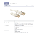
Short
T568A/B Passing Cable (Unshielded)
(1 not twisted with 2; 3 not twisted with 6)
Examples of Wiring Errors (Shielded)
1 2 3 4 5 6 7 8 S ID
Open
FAIL
Miswire
Split Pair
DARK = ON, LIGHT = FLASHING
1 2 3 4 5 6 7 8 S ID
1 2 3 4 5 6 7 8 S ID
FAIL
1 2 3 4 5 6 7 8 S ID
1 2 3 4 5 6 7 8 S ID
PASS

15
Battery Replacement
When the battery low icon is on, the battery
should be replaced as soon as practical. The
cable testing results will become unreliable
when the battery reaches about 4.5 volts.
To Replace Battery
Remove rubber battery cap by pressing
on bottom edge of the cap with the heel of
the hand until the cap pops off.
Pull battery out of cavity and remove
battery snap.
Connect a new Alkaline 9 volt battery to
battery snaps.
Slide battery into cavity and snap cap in
place.
When installing a new battery, disconnect
any cables connected to the tester. The
length and pre-test modes will be improperly
calibrated if a cable is present.
1)
2)
3)
4)

16
Specifications
Physical Dimensions
Size: 14. 5 cm x 7.2 cm x 3 cm (5.7" x 2.85" x 1.2")
Weight: 176 grams (6.2 oz.) with battery and remote
Environmental
Operating temperature: 0 to 50°C (32 to 122°F)
Storage temperature: –10 to 60°C (14 to 140°F)
Humidity: 10% to 90%, non-condensing
Battery Life (9V Alkaline battery, typical): times are
for the full capacity of the battery used
continuously in one of the following
modes — Standby: 2.5 years
Cable Testing: 120 hours
Cable Types: Shielded or unshielded, CAT3, CAT4,
CAT5, CAT5E CAT6 and Coaxial
Cable
Minimum cable length for testing for split pairs:
1 meter (3 feet)
Minimum cable length for PRE-TEST:
1.25 meter (4 feet)
Length measurement range (CAT5/6):
0 to 762 meters
(0 to 2500 feet)
Coax Cable: 100 ohms maximum DC resistance,
center conductor plus shield

17
Warranty
JDSU guarantees that its products will be free
of all defects in material and workmanship.
This warranty extends for the period of 12
months for test instruments and 3 months for
cables from date of manufacture or purchase
(proof of purchase required).
All product deemed defective under this
warranty will be repaired or replaced at JDSU’s
discretion. No further warranties either implied
or expressed will apply, nor will responsibility
for operation of this device be assumed by
JDSU.
WEEE Directive Compliance: JDSU has
established processes in compliance with the
Waste Electrical and Electronic Equipment
(WEEE) Directive, 2002/96/EC. This product
should not be disposed of as unsorted
municipal waste and should be collected
separately and disposed of according to your
national regulations. In the European Union,
all equipment purchased from JDSU after
2005-08-13 can be returned for disposal at the
end of its useful life. JDSU will ensure that all
waste equipment returned is reused, recycled,
or disposed of in an environmentally friendly
manner, and in compliance with all applicable
national and international waste legislation. It
is the responsibility of the equipment owner to
return the equipment to JDSU for appropriate
/