Page is loading ...

QUICK START GUIDE
DISPENSERS • HDE215
30636_B

QUICK START GUIDE
u-line.com
WELCOME TO U-LINE
ice making, refrigeration, and wine preservation experience. U-Line continues to be the American leader, delivering versatility
product collection includes Wine Captain
®
Models, Beverage Centers, Clear Ice Machines, Nugget Ice Machines, Crescent Ice
Makers, Glass & Solid Door Refrigerators, Drawer Models, Freezers, Combo
®
Models, and more.
and attention to even the smallest details. We are known and respected for our unwavering dedication to product design,
two decades and is proud to have the opportunity to ship to you.
PRODUCT INFORMATION
Looking for additional information on your product? User Guides, Spec Sheets, CAD Drawings, Compliance Documentation,
and Product Warranty information are all available for reference and download at u-line.com.
PROPERTY DAMAGE / INJURY CONCERNS
In the unlikely event property damage or personal injury is suspected related to a U-Line product, please take the following
steps:
1. U-Line Customer Care must be contacted immediately at +1.800.779.2547.
2. Service or repairs performed on the unit without prior written approval from U-Line is not permitted. If the unit has been
GENERAL INQUIRIES
U-Line Corporation
8900 N. 55th Street
Milwaukee, Wisconsin 53223 USA
Monday - Friday 8:00 am to 4:30 pm CST
T: +1.414.354.0300
F: +1.414.354.7905
Email: sales@u-line.com
u-line.com
SERVICE & PARTS ASSISTANCE
Monday - Friday 8:00 am to 4:30 pm CST
T: +1.800.779.2547
F: +1.414.354.5696
Service Email: onlineservice@u-line.com
Parts Email: onlineparts@u-line.com
CONNECT WITH US
Designed, engineered and assembled in WI, USA
2

QUICK START GUIDE
u-line.com
This Quick Start Guide covers the basics of installation and general use of your product.
For more details, see the complete User Guide & Service Manual on u-line.com.
This product is eligible for an additional one-year warranty at no charge when you register your product on u-line.com.
See complete warranty for details.
CONTENTS
Safety and Warning 4
Environmental Requirements 5
Electrical 5
Door Swing 5
Door Adjustments 6
General Installation 8
Control Operation 15
First Use 15
Cleaning 18
Warranty 20
D
e
s
i
g
n
e
d
,
e
n
g
i
n
e
e
r
e
d
,
a
n
d
a
s
s
e
m
b
l
e
d
i
n
M
i
l
w
a
u
k
e
e
,
W
I
,
U
S
A
t
o
b
e
r
e
m
o
v
e
d
b
y
e
n
d
c
o
n
s
u
m
e
r
o
n
l
y
2
*
v
i
s
i
t
u
-
l
i
n
e
.
c
o
m
f
o
r
d
e
t
a
i
l
s
1 year + 1 with registration
*
3

QUICK START GUIDE
u-line.com
Safety and Warning
NOTICE
Please read all instructions before installing,
operating, or servicing the appliance.
Use this appliance for its intended purpose only and follow
these general precautions with those listed throughout this
guide:
SAFETY ALERT DEFINITIONS
Throughout this guide are safety items labeled with a
Danger, Warning, or Caution based on the risk type:
Danger means that failure to follow this safety
statement will result in severe personal injury or
death.
Warning means that failure to follow this safety
statement could result in serious personal injury
or death.
Caution means that failure to follow this safety
statement may result in minor or moderate
personal injury, property, or equipment damage.
This unit contains R600a (Isobutane) which is a
ammable hydrocarbon. It is safe for regular
use. Do not use sharp objects to expedite
defrosting. Do not service without consulting the
“R600a specications” section included in the
User Guide. Do not damage the refrigerant
circuit.
Service must be done by factory authorized
service personnel. Any parts shall be replaced
with like components. Failure to comply could
increase the risk of possible ignition due to
incorrect parts or improper service.
CALIFORNIA PROPOSITION 65
This product contains chemicals known to the
state of California to cause cancer and birth
defects or other reproductive harm.
www.P65warnings.CA.gov
DANGER
!
DANGER
!
WARNING
!
CAUTION
!
WARNING
!
4

QUICK START GUIDE
u-line.com
Environmental Requirements
This model is intended for indoor/interior applications only
and is not to be used in installations that are open/
exposed to natural elements.
This unit is designed to operate between 50°F (10°C) and
100°F (38°C). Higher ambient temperatures may reduce
ice production on applicable models.
For best performance, keep the unit out of direct sunlight
and away from heat generating equipment.
In climates where high humidity and dew points are
present, condensation may appear on outside surfaces.
This is considered normal. The condensation will
evaporate when the humidity drops.
Damages caused by ambient temperatures of
40°F (4°C) or below are not covered by the
warranty.
Electrical
SHOCK HAZARD — Electrical Grounding
Required. Never attempt to repair or perform
maintenance on the unit until the electricity has
been disconnected.
Never remove the round grounding prong from
the plug and never use a two-prong grounding
adapter.
Altering, cutting or removing power cord,
removing power plug, or direct wiring can cause
serious injury, re, loss of property and/or life,
and will void the warranty.
Never use an extension cord to connect power to
the unit.
Always keep your working area dry.
NOTICE
Electrical installation must observe all state and
local codes. This unit requires connection to a
grounded (three-prong), polarized receptacle
that has been placed by a qualied electrician.
The unit requires a grounded and polarized 115 VAC,
60 Hz, 15A power supply (normal household current). An
individual, properly grounded branch circuit or circuit
breaker is recommended. A GFCI (ground fault circuit
appliances and is not recommended for your unit because
it could be prone to nuisance tripping. However, be sure
to consult your local codes.
See CUTOUT & PRODUCT DIMENSIONS for recommended
receptacle location.
Door Swing
Units have a zero clearance for the door to open 90
o
, when
installed adjacent to cabinets.
Stainless steel models require 2-1/8” (54 mm) door
clearance to accommodate the handle if installed next to a
wall.
CAUTION
!
5
1/4" Min.
Wall
21"
Wall
21"
16-1/2" 16-1/2"
2" Min.
90°
Door Swing
90°
Door Swing
Black and White Models
2115R Models
Stainless Models
Wall Wall
21"
16-1/2"
2" Min.
90°
Door Swing
Stainless Steel
21"
16-1/2"
90°
Door Swing
Black, White and Wood Overlay
1/4" Min.
2115WC Models
Wall
Wall
90°
Door Swing
Integrated
Stainless Steel, Black and White
90°
Door Swing
2175R(F) & 2275WC Models
90°
Door Swing
Wall Wall
21"
25-1/2"
90°
Door Swing
21"
25-1/2"
Stainless Steel
Wood Overlay
2175BEV
90°
Door Swing
Wall Wall
90°
Door Swing
Stainless Steel
2175WC Models
2-1/8" Min.
(54 mm)
1/4" Min.
(6 mm)
2-1/8" Min.
(54 mm)
1/4" Min.
(6 mm)
2-1/8" Min.
(54 mm)
1/4" Min.
(6 mm)
Black, White and Integrated

QUICK START GUIDE
u-line.com
6
USER GUIDE
Door Adjustments
u-line.com
Door Adjustments
HINGE COVER
Hinge cover included with the literature bag is optional.
To install hinge cover:
Press hinge cover squarely over hinge
DOOR ALIGNMENT AND ADJUSTMENT
Align and adjust the door if it is not level or is not sealing
properly. If the door is not sealed, the unit may not cool
properly, or excessive frost may form in the interior.
NOTICE
Properly aligned, the door’s gasket should be
firmly in contact with the cabinet all the way
around the door (no gaps). Carefully examine
the door’s gasket to ensure that it is firmly in
contact with the cabinet. Also make sure the
door gasket is not pinched on the hinge side of
the door.
To align and adjust the door:
1.
Gently pry off hinge cover from top of unit.
2.
Loosen (do not remove) top and bottom hinge screws
using a Torx T-25 screwdriver on the top and a 1/4”
socket on the bottom.
3.
Align door squarely with cabinet.
4.
Make sure gasket is firmly in contact with cabinet all
the way around the door (no gaps).
5.
Tighten bottom hinge screws.
6. Tighten top hinge screws and replace hinge cover.
REVERSING THE DOOR
Location of the unit may make it desirable to mount the
door on the opposite side of the cabinet.
The hinge hardware will be removed and reinstalled on the
opposite side of the cabinet.
TO REVERSE THE DOOR
Remove top hinge and door:
1. Remove hinge cover from top of unit.
2. Hold door to keep it from falling.
3. Remove top hinge from cabinet using a Torx T-25
screwdriver to remove three screws. Set aside and
save for possible future use.
Hinge Cover

QUICK START GUIDE
u-line.com
7
USER GUIDE
Door Adjustments
u-line.com
4. Remove door by tilting forward and lifting door off
bottom hinge. Retain shoulder washers; they will be
reused.
5. Remove three screws from hinge holes on the opposite
side. Reinstall into holes where the hinge was
removed. Take care not to scratch cabinet.
Remove bottom hinge:
1. Remove bottom hinge from cabinet using 1/4” socket.
2. Remove corresponding screws on opposite side of
cabinet. On some models there may be a nut behind
one or both screws on either side.
Install bottom hinge:
Install two or three screws, depending on model. Replace
nuts if used.
Prepare door for reinstallation:
1. Remove gasket.
2. Rotate gasket 180
o
and press firmly into the gasket
channel starting at the corners.
3. Rotate door 180
o
to reverse.
Install top hinge and door:
1. Remove pivot screw from hinge, flip hinge over, and
install the pivot screw in the same hole from the
opposite surface.
2. Rotate door 180
o
and
lift the door onto the bottom
hinge.
3. Align edge of the hinge with the outer edge of the unit.
4. Tighten three screws and replace hinge cover.
Align and adjust the door:
Align and adjust the door (see DOOR ALIGNMENT AND
ADJUSTMENT).
Top Hinge
Right Side
Top Hinge
Left Side
Pivot
Screw

QUICK START GUIDE
u-line.com
8
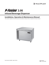
The following components are shipped inside the unit:
1. Double Tower (faucets, handles, gaskets, & hardware)
2. Nitrogen regulator (hose and valve)
3. Infuser regulator (hoses & hardware)
5. 2.5-gallon ball tap keg (you may use 3-gallon or 5-gallon keg)
6. Drip tray
7. Cleaning solution (2-ounce packet)
(Additional cleaner, ULACOFFEECLEAN, is available at u-line.com)
Safety and Warning
Keep nitrogen tank in an upright position and
handle with care.
Never exceed 60 PSI.
Ventilate area after nitrogen leak.
1
2
3
4
5
6
7
Required (not included):
1. Nitrogen tank with food grade nitrogen - available at
your local gas supplier. 22 cubic feet aluminum empty
tank available (ULANITROTANK) at u-line.com.
2.
General Installation
WARNING
!

QUICK START GUIDE
u-line.com
9
Install Tower on Free-Standing Refrigerator
If your refrigerator is new out of the box, do not remove all
is installed.
1. Remove four Phillips screws (secured with nuts on
to clear.
2. Position gasket over mounting hole and install tower
using four Phillips screws and nuts.
3. Screw the handles onto the faucets and continue to
assemble and connect regulator to Nitrogen tank.
Gasket

QUICK START GUIDE
u-line.com
10
Install Tower on Countertop
(See template on next page)
Note: These instructions are designed for a standard
36" countertop application.
Note: For a customized t, it may be necessary to
acquire screws that are sized to the thickness of your
countertop.
1. Position keg refrigerator under countertop to determine
the desired depth.
2. Use the dimensions from Diagram A to determine the
center point of the tower mounting hole.
3. Remove keg refrigerator from under countertop.
4. Use template to drill four mounting holes.
5. Drill 3-1/8" diameter hole through countertop.
6. Secure tower to countertop.
7. Screw the handles onto the faucets and continue to
CONNECTIONS in this User Guide.
Front Face
of Unit
3 ⁄”
(79 mm)
Hole Diameter
Power Cord
2”
(51 mm)
15”
(381 mm)
Rear Wall
24 ¼”
(616 mm)
11 ⁄”
(297 mm)
10 ⁄”
(257 mm)
1 ⁄”
(43 mm)
7 ½”
(19 1 mm)
Rear Wall
Countertop
10-1/8”
Front edge of hole
to front face of
refrigerator
Diagram A Diagram B

QUICK START GUIDE
u-line.com
11
Template for Countertop Installation
⁄” HOLE
3-⁄” HOLE
14 - ⁄”
To front face
of unit
7 - ⁄”
To side of unit
1 Inch
Note: Verify template has printed true to scale - double check hole dimensions and placement.

QUICK START GUIDE
u-line.com
12
Assemble and Connect Regulator
to Nitrogen Tank
1. Attach ball valve to tank regulator. Tighten with
position - turned clockwise as far as it can go.
2. Attach regulator to nitrogen tank. Hand tighten the
coupling nut and then use an adjustable wrench for an
additional quarter turn. DO NOT OVER TIGHTEN
1. Attach black nitrogen coupler of the liquid jumper line
to keg. With your thumb on top of the coupler, pull
valve. Release collar - listen for a click. Pull up on the
coupler to ensure it is locked down.
2. Attach other end of beverage hose to "Y" connection
3. Attach hose to elbow connector on infuser regulator.
Out Valve
Connect Keg to Dispenser Tower
Other end is
connected to keg
Elbow
Connector
Other end is
connected to
Tower

QUICK START GUIDE
u-line.com
13
1. Attach nitrogen
line to ball valve on tank regulator.
clockwise as far as it can go. Tighten hose clamp.
2. Attach other end of nitrogen
line to T connector on
Other end is
connected
to Infuser
Regulator
Connect Nitrogen Tank to Keg
3. Attach gray coupler of the gas jumper line to keg.
With your thumb on top of the coupler, pull up on
Release collar - listen for a click. Pull up on the
coupler to ensure it is locked down.
4. Attach other end of gas jumper line to T connector on
4. Attach other end of hose to the single connection
within the beverage tower.
In Valve
T-Connector
T-Connector

QUICK START GUIDE
u-line.com
14
Connections
When complete, the connections should look like this:
Nitrogen Tank
LEVELING INFORMATION
1.
unit is level. Level should
be placed along top edge
and side edge as shown.
2. If the unit is not level,
adjust the legs on the
corners of the unit as
necessary.
Keg
Infuser
Regulator
Tank
Regulator
Filter
Assembly
Turn to Adjust
3.
and repeat the previous steps until the unit is
level.
When ready to use, see FIRST USE section in
this manual.

QUICK START GUIDE
u-line.com
15
Control Operation
CONTROL FUNCTION GUIDE
FUNCTION COMMAND NOTES
ON/OFF Press and hold for 5 seconds Unit will turn On or OFF
Adjust Temperature Press or and release
adjust the set point temperature. Note: temperature
displayed is the actual temperature inside unit
Toggle between
º
F /
º
C Hold and for 5 seconds The display will change units
Temperature displayed reects actual
temperature inside unit.
Initial startup requires no adjustments. If the unit was
See “Control Operation” section for more details.
unit is progressing towards the selected temperature. Time
to reach set point varies based upon ambient temperature,
temperature of product loaded, door openings, etc. U-Line
recommends allowing the unit to reach set points before
loading.
assembled according to the instructions in GENERAL
INSTALLATION.
NOTICE
First Use
DE-PRESSURIZE SYSTEM
Fill the Keg
NOTICE
Before attempting to ll the keg it is necessary to
conrm system is not pressurized.
1.
it stops.
2. Lift up on pressure release valve ring. Allow pressure to
release.
3. Detach hoses from keg. (See General Installation
section of this guide.)

QUICK START GUIDE
u-line.com
4. Remove keg from refrigerator.
5. Lift handle and remove lid.
6. Fill keg with cold brew.
7. Replace and lock down lid.
8. Reattach hoses.
Set Nitrogen Pressure
The pressure should be set around 20 - 30 PSI. Start at 25
PSI on regulated gauge; 7 PSI at infuser regulator.
1. Make sure red regulator valve is in the OFF position.
2. On top of Nitrogen tank, turn black handle
counterclockwise until it stops.
3. Rotate the red regulator valve to ON Position; turn
TO ADJUST PRESSURE
1. Loosen locking nut, turn adjusting screw until desired
pressure is reached, and retighten locking nut.
2. On infuser regulator, pull out middle knob to unlock
then turn knob until needle points at 7 - turn right to
increase; left to decrease.
3. Once set, lock in place by pressing middle knob in until
it clicks.
Lock
Unlock
Adjusting
Screw
Locking
Nut
Regulated
Gauge
Tank Pressure
Gauge
16

QUICK START GUIDE
u-line.com
Dispensing Coee
-
pensed. This creates a naturally slightly sweet taste and thicker and smoother texture.
Troubleshooting
ISSUE CAUSE SOLUTION
through faucet(s).
is clogged or beginning to clog.
See cleaning section
If applicable, assure that the nitrogen tank is not empty and
the tube). Also assure that the knob on top of the tank is turned
all the way counterclockwise. If the tank is empty, replace it
with a full one.
Liquid and/or nitrogen ball lock disconnects
are not fully connected to product tank.
Attach the liquid/nitrogen ball lock disconnects to the product
tank. If they already appear to be connected, disconnect/
reconnect them.
The nose cone of the faucet is clogged. Detach the nose cone assembly from the stout faucet by turning
it counterclockwise. Remove the stainless steel restrictor disc
and inspect the small holes to assure that none of them are
clogged.
The system is dirty and requires a thorough
line cleaning/sanitizing procedure.
Follow the line cleaning procedure above to remove buildup and
Too much or not enough
nitrogen being infused
into the product (head is
too big or too small).
The secondary regulator is set to a pressure
that is either too high or low.
knob on the secondary regulator assembly to make a change.
To adjust the secondary regulator, pull the black knob out until
you feel a slight click. This is the adjustment mode. To increase
the level of nitro, turn this knob clockwise. To decrease the level
of nitro, turn the knob counterclockwise. Continue adjusting and
pouring until the level of nitro meets your requirements. Once
you have found your desired level of nitrogenation, push the
black knob back in to lock it in place.
is beginning to clog.
See cleaning section
The system is dirty and needs cleaned. See cleaning section
Liquid leak.
assembly.
the quick disconnects from the product tank and call customer
support for consultation to assess the system.
Nitrogen leak (system
is using nitrogen even
when faucets are
closed).
Product tank lid is not sealed completely. Remove the lid and reattach making sure that the lid is centered
and sealed.
Fitting is loose, disconnected, or broken.
the quick disconnects from the product tank and call customer
support for consultation to assess the system.
The product is pouring
too warm/cold or is
freezing in the lines.
Hot/Warm - The refrigeration is not plugged
in or turned on.
Plug in the refrigerator and assure it is powered on.
Frozen - The thermostat on the refrigeration
needs adjusted.
See control section
The condenser coil on the refrigeration is dirty
and needs cleaned.
See condenser cleaning
17

QUICK START GUIDE
u-line.com
18
Stainless Models
Stainless door panels, handles and frames can discolor
when exposed to chlorine gas, pool chemicals, saltwater or
cleaners with bleach.
Keep your stainless unit looking new by cleaning with a
good quality all-in-one stainless steel cleaner and pol-
ish monthly. For best results use Claire
®
Stainless Steel
Polish and Cleaner. Comparable products are acceptable.
Frequent cleaning will remove surface contamination that
could lead to rust. Some installations may require cleaning
weekly.
Do not clean with steel wool pads.
Do not use stainless steel cleaners or polishes on
any glass surfaces.
Clean any glass surfaces with a non-chlorine glass cleaner.
Do not use cleaners not specically intended for
stainless steel on stainless steel surfaces (this
includes glass, tile, and counter cleaners).
Cleaning
If any surface discoloring or rusting appears, clean it
quickly with Bon-Ami
®
or Barkeepers Friend Cleanser
®
and
a nonabrasive cloth. Always clean with the grain. Always
®
Stainless Steel Polish and Cleaner or
comparable product to prevent further problems.
Using abrasive pads such as ScotchBrite™ will
cause the graining in the stainless steel to
become blurred.
Rust not cleaned up promptly can penetrate the
surface of the stainless steel and complete
removal of the rust may not be possible.
INTERIOR CLEANING
Disconnect power to the unit.
Clean the interior and all removed components using a
mild nonabrasive detergent and warm solution applied with
a soft sponge or non-abrasive cloth.
Rinse the interior using a soft sponge and clean water.
Do not use any solvent-based or abrasive
cleaners. These types of cleaners may transfer taste
and/or odor to the interior products and damage or
discolor the interior.
DEFROSTING
Under normal conditions this unit does not require manual
defrosting. Minor frost on the rear wall or visible through
the evaporator plate vents is normal and will melt during
each cycle.
If there is excessive build-up of 1/4” (6 mm) or more,
manually defrost the unit.
Ensure the door is closing and sealing properly.
High ambient temperature and excessive humidity can also
produce frost.
CAUTION
!
DO NOT use an ice pick or other sharp instrument
to help speed up defrosting. These instruments
can puncture the inner lining or damage the
cooling unit. DO NOT use any type of heater to
defrost. Using a heater to speed up defrosting can
cause personal injury and damage to the inner
lining.
Restricting airow may result in poor product
performance, product failure, and uneven internal
temperatures and may freeze contents.
• Do not block the front grille - no additional clearance
around sides, top or rear of unit is needed for ventilation
• Do not install behind a closed door
• When loading, leave space between internal fans, vents,
and side walls to allow air to circulate freely
NOTICE
AIRFLOW
External
Internal
Airow and Product Loading

QUICK START GUIDE
u-line.com
NOTICE
The drain pan was not designed to capture the
water created when manually defrosting. To
prevent water from overowing the drain pan
and possibly damaging water sensitive ooring,
the unit must be removed from cabinetry.
To defrost:
1. Disconnect power to the unit.
2. Remove all products from the interior
3. Prop the door in an open position (2 in. [50 mm]
minimum).
4. Allow the frost to melt naturally.
5. After the frost melts completely, clean the interior and
all removed components.
6. When the interior is dry, reconnect power and turn
unit on.
Cleaning the System
The system should be cleaned each time you change your
a solution of water and ULACOFFEECLEAN. One packet of
ULACOFFEECLEAN (Stera-Sheen®) was included with your
product and more can be purchased at u-line.com.
Notice
Conrm system is not pressurized by turning
o nitrogen – turn handle clockwise. Release
pressure in system by pulling up on the release
valve.
Cleaning Solution Preparation
Follow safety instructions on
packet. Mix ULACOFFEECLEAN with
2 gallons of warm (100°F/38°C)
potable water.
Tap Heads
Clean the faucet with warm soapy
water. Remove nose cone and soak in the cleaning solution
dry and reattach.
Infuser Filter
with warm potable water and reassemble.
Line and System Cleaning
1. Remove the contents, clean the keg with water warm
soapy water, and rinse.
2. Pour the cleaning solution into keg, attach hoses and
open the nitrogen valve to pressurize the system.
3. Place a bucket under the taps. Pull and hold the left
tap open until approximately ½ gallon of cleaning
solution is dispensed. Close the left faucet. Pull and
hold the right faucet handle until ½ gallon of solution
is dispensed. Discard solution.
4. Allow the cleaning solution to remain in the system for
5. Dispense approximately ¼ gallon of the solution
through the left tap. Dispense the remaining solution
from the right tap. No rinsing is required.
6.
dry.
Nose Cone
Cap
Filter
19

Copyright © 2020 U-Line Corporation. All Rights Reserved. | Publication Number 30379 | 01/2020 Rev. N
U-Line Corporation (U-Line) Limited Warranty
One Year Limited Warranty
For one year from the date of original purchase, this warranty covers all parts and labor to repair or replace any part of the product that
proves to be defective in materials or workmanship. For products installed and used for normal residential use, material cosmetic defects
are included in this warranty, with coverage limited to 60 days from the date of original purchase. All service provided by U-Line under the
above warranty must be performed by a U-Line factory authorized servicer, unless otherwise specified by U-Line. Service provided during
normal business hours.
Two Year Limited Warranty (5 Class Product)
For two years from the date of original purchase, this warranty covers all parts and labor to repair or replace any part of the product that
proves to be defective in materials or workmanship. For products installed and used for normal residential use, material cosmetic defects
are included in this warranty, with coverage limited to 60 days from the date of original purchase. All service provided by U-Line under the
above warranty must be performed by a U-Line factory authorized servicer, unless otherwise specified by U-Line. Service provided during
normal business hours.
Available Second & Third Year Limited Warranty
In addition to the standard one and two year warranties outlined above, U-Line offers a one year extension of the warranties from the date
of purchase, free of charge. To take advantage of this extension, you must register your product with U-Line within 60 days from the date
of purchase at u-line.com and provide proof of purchase.
Five Year Sealed System Limited Warranty
For five years from the date of original purchase, U-Line will repair or replace the following parts, labor not included, that prove to be
defective in materials or workmanship: compressor, condenser, evaporator, drier, and all connecting tubing. All service provided by U-Line
under the above warranty must be performed by a U-Line factory authorized servicer, unless otherwise specified by U-Line. Service
provided during normal business hours.
Terms
These warranties apply only to products installed in any one of the fifty states of the United States, the District of Columbia, or the ten
provinces of Canada. The warranties do not cover any parts or labor to correct any defect caused by negligence, accident or improper use,
maintenance, installation, service, repair, acts of God, fire, flood or other natural disasters. The product must be installed, operated, and
maintained in accordance with your product’s User Guide.
The remedies described above for each warranty are the only ones that U-Line will provide, either under these warranties or under any
warranty arising by operation of law. U-Line will not be responsible for any consequential or incidental damages arising from the breach of
these warranties or any other warranty, whether express, implied, or statutory. Some states do not allow the exclusion or limitation of
incidental or consequential damages, so the above limitation or exclusion may not apply to you. These warranties give you specific legal
rights, and you may also have other rights which vary from state to state.
Any warranty that may be implied in connection with your purchase or use of the product, including any warranty of merchantability or any
warranty fit for a particular purpose is limited to the duration of these warranties, and only extends to five years in duration for the parts
described in the section related to the five year limited warranty above. Some states do not allow limitations on how long an implied warranty
lasts, so the above limitations may not apply to you.
• The warranties only apply to the original purchaser and are non-transferable.
• The second, third, and five year warranties cover products installed and used for normal residential or designated marine use only.
• The warranties apply to units operated outside only if designed for outdoor use by model and serial number.
• U-Line Commercial products are covered by the one year and 5 year limited warranties and are not eligible for the second and
third year limited warranties.
• Replacement water filters, light bulbs, and other consumable parts are not covered by these warranties.
• The start of U-Line’s obligation is limited to four years after the shipment date from U-Line.
• In-home instruction on how to use your product is not covered by these warranties.
• Food, beverage, and medicine loss are not covered by these warranties.
• If the product is located in an area where U-Line factory authorized service is not available, you may be responsible for a trip
charge or you may be required to bring the product to a U-Line factory authorized service location at your own cost and expense.
• Units purchased after use as floor displays, and/or certified reconditioned units, are covered by the limited one year warranty only
and no coverage is provided for cosmetic defects.
• Signal issues related to Wi-Fi connectivity are not covered by these warranties.
For parts and service assistance, or to find U-Line factory authorized service near you, contact U-Line:
8900 N. 55
th
Street, Milwaukee, WI 53223 • u-line.com • onlineservice@u-line.com • +1.800.779.2547
20
/