Techno line WS 2350 Owner's manual

Category
Weather stations
Type
Owner's manual
51
Operation Manual
Professional Remote Weather Station
Table of Contents
Page
1.
Introduction………… .................................................................. 52
2. Intended use .............................................................................. 52
Weather Station ......................................................................... 52
System requirements for PC use ................................................ 53
Installation for the USB adapter driver ........................................ 53
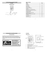
Features of the base station ....................................................... 54
Features of the thermo-hygro sensor.......................................... 55
Features of the wind sensor ....................................................... 55
Features of the rain sensor......................................................... 55
3. Safety Notes .............................................................................. 55
4. Packaged contents ..................................................................... 57
5. Setting up ................................................................................... 58
6. Operation using cable connection or wireless 433MHz............... 61
7. LCD overview ............................................................................. 63
8. Function test .............................................................................. 64
9. Mounting .................................................................................... 64
10. Resetting & factory settings ........................................................ 68
11. Function description ................................................................... 70
12. Operation keys ........................................................................... 73
13. Basic programming modes ......................................................... 75
14. MIN/MAX programming modes .................................................. 76
15. Alarm programming modes ........................................................ 78
16. Auto-memory for stored values .................................................. 87
17. Accessories: extensions cables .................................................. 87
18. Changing batteries ..................................................................... 88
19. Interference and problems with operation ................................... 89
20. Transmission range .................................................................... 90
21. Cleaning and maintenance ......................................................... 91
22. Specifications ............................................................................. 91
23. Liability disclaimer ...................................................................... 93
This Operation Manual is part of this product and should be kept in a safe
place for future reference. It contains important notes on setup and opera-
tion.
52
Please visit our web site www.heavyweather.info for downloads of complete
instruction manuals and the most current version of the 'Heavy Weather'
software.
1. Introduction
Thank you for purchasing this Professional Remote Weather Sta-
tion.
Designed for everyday use, the weather station will prove to be an
asset of great value for your personal use in the home or office.
Please read this instruction manual thoroughly to fully understand
the features and functions so that you can enjoy the safe and cor-
rect operation of this unique product.
2. Intended Use
Weather Station
The base station measures the indoor environment of its surround-
ing area and receives weather data from the following three outdoor
sensors:
1) Thermo-Hygro Sensor
2) Wind Sensor
3) Rain Sensor
The received data is continuously updated to bring you the latest
weather information on the base station’s LCD. The thermo-hygro
sensor is the main data communication unit since both the wind
and rain sensors are connected to the thermo-hygro sensor for
operating power and rely on it to communicate to the base station.
Weather data sent from the thermo-hygro sensor can be done by
wireless 433MHz transmission (up to 100 meters in open space) or
by cable connection.
Using the enclosed 2 meter computer cable and CD-ROM, you can
install the Heavy Weather software to your PC and upload all the
received weather data from the base station. Access the latest
weather information from your PC and upload up to 175 sets of
recorded weather data by the base station and generate useful
statistics and charts onto your spreadsheets (175 sets of data is
stored in the base even if the PC is switched OFF). The software
53
itself does not set any limits as to how many data sets that can be
transferred to PC.
This weather station is designed to work easily with your PC.
There are no tedious requirements to turn your PC ON or OFF,
simply connect and disconnect the PC cable at any time.
System Requirements for PC use:
The minimum system requirement for use of this “Heavy Weather”
software is:
Operating system: Windows 98 or above
Processor: Pentium 166 MHz or above
RAM: 32MB of RAM or above
Hard disk: 20MB free space
CD-ROM drive
Installation for the USB adapter driver
1- Find the Heavy Weather CD-ROM within the packaging.
2- Plug in the USB adapter to the computer.
3- Follow the Windows Installation steps to find the driver.
Select “ Install from a list of specific location (Advanced)”
4- Install the CD-ROM to CD drive.
5- From the list that appears select:
E:\USB\ where E: is the location of the CD drive.
Note:
For the latest USB adapter driver, please visit:
http://www.ftdichip.com/Drivers/VCP.htm
For the detail installation instruction for the USB adaptor, please visit:
http://www.ftdichip.com/Documents/InstallGuides.htm
After installing the USB Adapter Driver check in Device Manager to confirm
that Windows has recognized the adapter:
To determine which COM Port your USB adapter is on:
1- Find MY COMPUTER and “right click” the icon.
2- Select MANAGE.
3- Click on DEVICE MANAGER.
54
4- You should see COM Ports listed with numbers after them Ex: Com-
munications Port (COM 1), USB to Serial Bridge (COM 4).
If you do not see a COM setting, your computer does not recognize
your USB driver.
5- If the USB adapter is not on COM port 1, 2, 3 or 4 you will need to
change it.
6- Double click the COM Port Ex: (COM 7) this will bring up a Communi-
cations Port Properties Box. Click the Port Settings Tab, Click Ad-
vanced.
7- Click the Drop Down next to the COM port number and select Com 1,
2, 3, or 4. If they are IN USE see your computer person BEFORE
changing.
After configuring the adapter, connect the weather station and open the
Heavy Weather software. Click SETUP button and select the proper COM
Port. Data should begin to download within a minute or two.
Features of the base station:
Receives and displays the DCF77 radio controlled time and date
Display of extensive weather data, in all cases with programmable
alarm functions for certain weather conditions as well as records of
all minimum and maximum values along with time and date of their
recordings
Indoor and outdoor temperature and relative humidity displays in
degrees Fahrenheit or Celsius (user selectable)
Indoor and outdoor relative humidity displays
Air pressure reading in inHg or hPa, absolute or relative (user
selectable)
Detailed display of rainfall data in 1 hour, 24 hours, total since last
reset (user selectable in mm or inch)
Wind speed in mph, km/h, m/s, knots or Beaufort (user selectable)
Wind direction display with LCD compass as well as numerical
(e.g. 225°) and abbreviated characters (e.g. SW)
Wind chill temperature display
Dew point temperature display
Weather forecast display by weather icons (sunny, cloudy, rainy)
Weather tendency indicator
Storm warning alarm
LED back light
55
Simultaneous display of all weather data with individual settings by
the user
COM port for easy connection to your PC
All the weather data from the base station and up to 175 sets of
weather history data with user adjustable measuring intervals can
be recorded and uploaded to your PC
Features of the Thermo-Hygro Sensor
The thermo-hygro sensor measures the outdoor temperature and
relative humidity. It also collects the readings from the rain and
wind sensors before transmitting the data to the base station by
wireless 433MHz or by the 10 meter cable included in this set.
Features of Wind sensor
The wind sensor measures wind speed and wind direction and
sends the data to thermo-hygro sensor which in turn transmits the
data to the base station. Operating power is taken from the ther-
mo-hygro sensor using a 10 meter cable connection.
Features of Rain sensor
The rain sensor measures the rainfall and sends the data to ther-
mo-hygro sensor which in turn transmits the data to the base sta-
tion. Operating power is taken from the thermo-hygro sensor by a
10 meter cable connection.
3. Safety Notes
Damage caused by failure to comply with this instruction manual
will invalidate any guarantee! The manufacturer and supplier will
not be held liable for actions due to failure to comply with this in-
struction manual or from data inaccuracies that may occur with this
product!
In case of harm or damage to a person or property caused by
improper handling or failure to comply with this instruction manual,
the manufacturer and supplier cannot be held liable.
For reasons of safety and operation, alterations to this device are
strictly prohibited.
56
To operate the weather station, use only supplied adaptor and
batteries of the recommended type.
Do not leave used-up batteries in the device as these may corrode
and release chemicals that may damage the unit.
Inserting batteries in an incorrect polarity will cause damage to this
product.
This product is not a toy kept out of the reach of children.
Do not depose new or used batteries to fire as they may explosion
or release dangerous chemicals.
This product is not to be used for medical purposes or for public
information.
57
4. Packaged Contents
Before setting up, carefully unpack the contents onto a table or flat
surface and check that the following are complete:
Item:
Consisting of:
Fittings:
Illustration:
Base
Station
Main unit
AD/DC 230V power
Adaptor - optional use
(included)
Thermo-
Hygro
Sensor
Main unit
Rain protection
cover
10 meter cable -
optional connection to
the base station (in-
cluded)
Wall mounting screws
Plastic anchors for
screws
Wind
Sensor
Main unit with
wind vane
10 meter cable
(already at-
tached to the
main unit)
Mast holder
L-shaped
extension
1 x U-bolts for mast
holder
2 x Washers
2 x Nuts
2 x Plastic cable ties
Rain
Sensor
Main unit (base
and funnel)
10 meter cable
(already at-
tached to the
main unit)
Heavy
weather
PC
software
CD-Rom format
(English,
German and
French languages
only)
2 meter PC cable for
PC connection - op-
tional use (included)
58
Battery compartment
Socket for
Adaptor
5. Setting up
Firstly, choose to use the adaptor (included in this set) or batteries
for operation. Both these methods allow for operation of using
wireless 433MHz transmission or cable connection between the
base station and the sensors and setting up for both methods is as
follows:
Base Station:
Socket for
Thermo-
Hygro
Sensor
PC COM
Port
59
Setting up using batteries:
Important: To avoid operating problems, please take note of
battery polarity if inserting any batteries
1) Pull away the rain cover of the thermo-hygro sensor to reveal
the three sockets (for the wind sensor, rain sensor and the
base station)
2) Connect the attached cables of wind and rain sensors to the
corresponding sockets of the thermo-hygro sensor by clicking
them into place
3) Open the battery cover of the thermo-hygro sensor located
below the three sockets and insert 2 x AA, IEC LR6, 1.5V bat-
teries and close the cover
Battery
Compartment
Battery Cover
Thermo
-
Hygro Sensor
Sensor sockets
Sensor sockets
60
4) Open the base station’s battery cover located at the back of
the unit and insert 3 x AA, IEC LR6, 1.5V batteries into the bat-
tery compartment and close the battery cover
Setting up using the AC adaptor:
1) Power up all the sensors as described in setting up using bat-
teries above
2) Using the AC adaptor (included), plug it into the mains outlet
and power up the base station by inserting the adaptor jack in-
to the 6.0V DC socket located on the side of the base station
Every time the thermo-hygro sensor is powered up (for example
after a change of batteries), a random security code is transmitted
and this code must be synchronized with the base station to receive
weather data.
When the base station is powered up, a short beep will sound and
all LCD segments will light up for about 5 seconds before it enters
into a 15 minute learning mode to learn the sensors security code.
After the learning mode (or by pressing the MIN/MAX key at any-
time), the base station will start the DCF77 radio controlled time
reception.
Note for DCF77 Radio Controlled Time:
The time and date display is based on the signal provided by a
highly accurate Caesium atomic clock operated by the Physikalisch
Technische Bundesamt in Braunschweig (Germany). This radio-
controlled clock does not only provide for the weather station’s time
and date display but also functions as the time source for all of this
weather station’s memory and history values using time and date
information.
LCD backlight:
When using the power adaptor or under battery operation, the LCD
backlight will switch on for 15 seconds when any key is pressed.
61
6. Operation using cable connection or wireless 433MHz
Cable Connection:
Using this method of operation will provide interference free trans-
fer of the weather data from the sensors to the base station. The
data sending interval from the sensors to the base station will also
be more frequent compared to using 433MHz transmission and will
result in higher power consumption. Therefore batteries will have a
shorter life span for cable connection compared to using 433MHz.
To operate using cable connection, simply use the enclosed 10
meter cable and connect the thermo-hygro sensor to the base sta-
tion. Once the connection is detected, the base station will automat-
ically continue reading the data from the sensor.
The user may at any time switch from cable connection to using
433MHz (or vice versa) by simply disconnecting (or connecting) the
cable from the base station to the sensor. When the base station
detects no cable connection to the sensors, the existing data read-
ing interval is changed to the new reading interval, i.e. using cable
connection is every 8 seconds data reading interval or from 32
seconds - 128 seconds intervals when using 433MHz (depending
on wind speed)
Using the AC adaptor to operate the base station will also supply
power to the sensor if the cable is connected to it. Batteries used
for 433MHz transmission may be left in the sensor when using
cable connection for power back-up in case of AC power failure. A
loss of power would desynchronize the base station and the sensor
and no weather data will be received. To Synchronize the units so
that the weather data can be received, press and hold the PLUS(+)
for 2 seconds. However in general, batteries that will not be used
for long periods should be removed to avoid leakage.
Wireless 433MHz transmission:
Using 433MHz wireless transmission of weather data from the
sensor to the base station will provide users greater freedom as to
where units can be positioned without the need to be restricted by
cable.
62
Note:
If no outdoor weather data is displayed or the signal to the sensors
is lost during setting up, mounting, changing of batteries to the
sensor or plugging or unplugging cables, simply press and hold the
PLUS(+) key for 2 seconds and a short beep will sound to syn-
chronize the base station to sensors. Without being synchronized,
weather data will not be received.
63
1. Low battery indicator
2. DCF77 radio controlled time icon
3. Date display
4. Time zone display
5. Date, seconds, alarm time and time
zone
6. Alarm icon
7. Weather forecast icons
8. Weather tendency indicator
9. Pressure alarm display
10. hPa/inHg air pressure unit
11. Pressure units (relative or absolute)
12. 433MHz reception icon
13. Rainfall display
14. Indoor, outdoor, humidity, dew
point, wind chill, rainfall alarm icon
15. 24h, 1h or total hour display
16. Humidity display as RH%
17. Rainfall units (inch or mm)
18. Temperature display units (ºC or ºF)
19. Outdoor temperature/humidity
display
20 Indoor temperature/humidity display
21. Dew point temperature display
22. Wind chill temperature display
23. Wind alarm icon
24.
Wind information for Min/Max speed
and wind speed low, high, direction
alarm
25. Wind direction and speed (m/s,
knots, Beaufort, km/h or mph) dis-
play
26. Alarm buzzer ON/OFF icon
27. General alarm icon
7. LCD Overview
The following illustration shows the full segments of the LCD for description
purposes only and will not appear like this during normal operation and use.
16
1
2
3
4
5
6
7
8
9
10
13
12
14
15
17
23
11
19
20
22
21
18
24
25
26
27
64
8. Function test:
Once the weather station is powered up, perform a function test by
checking that the weather data is received. To do this, press the
either DISPLAY, PRESSURE or WIND keys to toggle through the
relevant LCD sections:
1) Indoor temperature and humidity
2) Outdoor temperature and humidity
3) Outdoor wind chill
4) Dew point
5) Rainfall 24 hour
6) Rainfall 1hour
7) Rainfall Total
8) Relative and absolute pressure
9) Wind speed, wind direction and wind direction in degrees
If any readings cannot be received from the sensors, lines (- - -) will
be displayed in the respective weather sections of the LCD. In this
case, check that all cables are correctly inserted into the correct
sockets and press and hold the PLUS(+) key for 2 seconds and a
short beep will sound to synchronize the base station to the sen-
sors otherwise no weather data will be received.
Some weather readings such as wind speed and direction may not
appear immediately on the LCD if the wind-fan or vane of the wind
sensor is moved. This is due to the set reading time intervals for
the wind readings. However the current wind speed or direction will
be displayed once the time reading interval is reached. For rainfall,
the interval readings may take up to 2 minutes before the data is
displayed on the LCD.
9. Mounting
Important Note
Prior to drilling mounting holes and permanently affixing any of the
units, please ensure the following points are considered:
Cable lengths of the units meet with your distance require-
ments at the point of fixing
65
Signals from the sensors can be received by the base station
at points of mounting
Radio controlled time signal can be received at the point of
mounting
Base Station
With two foldable legs at the back of the unit, the base station can
be placed onto any flat surface or wall mounted at the desired loca-
tion by the hanging holes also at the back of the unit. It is important
to check that the 433MHz (if using wireless connection) and the
DCF77 radio controlled time signal can be received before perma-
nently mounting any of the units. Should the base station not dis-
play the 433MHz weather data from the sensors or the radio con-
trolled time from the desired location, then relocate the units. Once
the signals are received, the system can be affixed. Also if you
have selected to use cable connection, ensure that distances can
reach all desired locations before affixing any unit permanently
Mounting the Wind Sensor
The remote wind speed sensor can be mounted two ways:
With the use of screws
Using nylon straps
Mounting with screws
Horizontal panel
Wind vane
Fixed with screw
66
1. Unlock the mounting bracket from the remote wind speed sen-
sor leaving the wire going through the bracket.
2. Place the mounting bracket over the desired location.
3. Through the two screw holes of the bracket, mark the mounting
surface with a pencil.
4. Screw the mounting bracket onto the mounting surface. En-
sure that the screws are tight against the bracket.
5. Slide the remote wind speed sensor onto the bracket making
sure to lock it in place.
MOUNTING WITH NYLON STRAPS
1. Unlock the mounting bracket from the remote wind speed sen-
sor leaving the wire going through the bracket.
2. Place two nylon straps through the slots on the mounting
bracket.
3. Place the remote wind speed sensor in your desired location.
4. Fasten the two nylon straps securely around the mounting
location.
5. Slide the remote wind speed sensor onto the bracket making
sure to lock it in place.
Once the wind sensor is fixed onto the mast, connect the cable to
the corresponding thermo-hygro sensor socket so that operating
power supply can be received and data can be transmitted to the
base station.
Vertical mast
Wind fan
Fixed with Nylon strap
67
Mounting the Rain Sensor
For best results, the rain sensor should be securely mounted onto a
horizontal surface about 1 meter above the ground and in an open
area away from trees or other coverings where rainfall may be
reduced causing inaccurate readings.
When securing into place, check that rain excess will not collect
and store at the base of the unit but can flow out between the base
and the mounting surface (test by pouring clean water).
After mounting the rain sensor, connect the cable to the thermo-
hygro sensor at the corresponding socket so power supply can be
received and data be transmitted to the base station
The rain sensor is now operable. For testing purposes, very slowly
pour a small amount of clean water into the rain sensor funnel. The
water will act as rainfall and will be received and displayed at the
base station after about 2 minutes delay i.e. when the reading in-
terval is reached (to clear this testing data on the base station, refer
to the section “MIN/MAX Mode” below).
Mounting the thermo-hygro Sensor
Base portion
Funnel portion
Rain Cov-
er
Wall Bracket
Main Unit
68
An ideal mounting place for the thermo-hygro sensor would be the
outer wall beneath the extension of a roof, as this will protect the
sensor from direct sunlight and other extreme weather conditions.
To wall mount, use the 2 screws to affix the wall bracket to the
desired wall, plug in the thermo-hygro sensor to the bracket and
secure both parts by the use of the supplied screw and ensure that
the cables from the wind and rain sensors are correctly plugged in
otherwise data transmission errors could occur.
10. Resetting & factory settings:
As previously mentioned, in the event of a power reset to the sen-
sor (for example a change of batteries), the base station has to
synchronize to the sensor again otherwise no weather data will be
received. To do this, simply press and hold the PLUS(+) key for 2
seconds and a short beep will sound to synchronize the base sta-
tion to the sensor. When the units are synchronized, the data will
be received again and the base station will return to normal opera-
tion mode.
Do not reset the power of the base station otherwise all 175 sets of
recorded weather history data for transferring to the PC will be lost
(for full details of PC use, please see PC user manual in the en-
closed Heavy Weather CD-ROM).
However if you wish to make a full reset of the base station and
return to the original factory settings, simultaneously press and hold
the PRESSURE and WIND keys for about 5 seconds. The base
station will beep once and the entire LCD will light up for 5 seconds
and go back to the original factory settings. This process with clear
all previous user defined values and all weather history recordings.
69
Factory default settings:
The following table shows the factory default values of the weather
station:
Matter:
Default Setting:
Time 0:00
Date 01.01.2001
Time zone 0
Alarm time 0:00
Relative air pressure 1013.0 hPa
Weather-picture threshold 3 hPa
LCD contrast level 5 (1-8 levels)
Rainfall per impulse 0.518mm
Storm alarm 5 hPa
Relative air pressure alarm 960.0 hPa (low) 1040.0 hPa (high)
Indoor temperature alarm 10.0ºC (low) 30.0ºC (high)
Outdoor temperature alarm 0.0ºC (low) 40.0ºC (high)
Indoor humidity alarm 35%RH (low) 65%RH (high)
Outdoor humidity alarm 45%RH (low) 70%RH (high)
Wind chill alarm 10.0ºC (low) 30.0ºC (high)
Dew point alarm 0.0ºC (low) 30.0ºC (high)
Rainfall 24h alarm 50.0mm
Rainfall 1h alarm 1.0mm
Wind Speed 1km/h (low) 100km/h (high)
Wind direction alarm None set
Note:
All alarm default values are deactivated at the start up and any
alarm must be activated by the user otherwise it will not sound.
70
11. Function Description of the Weather Station
After setting up, the following data will be displayed in different
sections on the LCD. If this is not the case please observe the
notes on “Interferences” below.
Time & Date (LCD Section 1)
If the DCF77 icon (icon 2) is ON and not flashing, it means that the
DCF77 radio-controlled time and date are has been received. Press
the PLUS(+) key to change the format of date display between
date/month/year, weekday/date/month, seconds, alarm set time
and time zone.
Weather forecasting (LCD Section 1)
The three weather icons Sunny, Cloudy and Rainy represent the
weather forecasting. There are also two weather tendency indica-
tors to show the air pressure tendency either side of the weather
icons.
LCD Section 1:
Time, date, seconds, time zone,
weather forecasting icons with
tendency arrows, air pressure,
and respective alarms sections
LCD Section 2
:
Indoor and outdoor temperature
and rela
tive humidity, wind chill,
dew point, rainfall, and respec-
tive alarms sections
LCD Section 3:
Wind direction, wind speed, and
respective alarms sections
  • Page 1 1
  • Page 2 2
  • Page 3 3
  • Page 4 4
  • Page 5 5
  • Page 6 6
  • Page 7 7
  • Page 8 8
  • Page 9 9
  • Page 10 10
  • Page 11 11
  • Page 12 12
  • Page 13 13
  • Page 14 14
  • Page 15 15
  • Page 16 16
  • Page 17 17
  • Page 18 18
  • Page 19 19
  • Page 20 20
  • Page 21 21
  • Page 22 22
  • Page 23 23
  • Page 24 24
  • Page 25 25
  • Page 26 26
  • Page 27 27
  • Page 28 28
  • Page 29 29
  • Page 30 30
  • Page 31 31
  • Page 32 32
  • Page 33 33
  • Page 34 34
  • Page 35 35
  • Page 36 36
  • Page 37 37
  • Page 38 38
  • Page 39 39
  • Page 40 40
  • Page 41 41
  • Page 42 42
  • Page 43 43
  • Page 44 44

Techno line WS 2350 Owner's manual

Category
Weather stations
Type
Owner's manual

Ask a question and I''ll find the answer in the document

Finding information in a document is now easier with AI