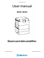
Munters MG: Advanced Dehumidification Solutions for Optimal Air Quality
With the Munters MG desiccant dehumidifier, you've made a wise choice for managing humidity levels efficiently. Experience precise dehumidification with its ability to effectively remove excess moisture from the air. Protect your environment from the damaging effects of high humidity, ensuring a comfortable and healthy atmosphere.


-
 1
1
-
 2
2
-
 3
3
-
 4
4
-
 5
5
-
 6
6
-
 7
7
-
 8
8
-
 9
9
-
 10
10
-
 11
11
-
 12
12
-
 13
13
-
 14
14
-
 15
15
-
 16
16
-
 17
17
-
 18
18
-
 19
19
-
 20
20
-
 21
21
-
 22
22
-
 23
23
-
 24
24
-
 25
25
-
 26
26
-
 27
27
-
 28
28


Munters MG: Advanced Dehumidification Solutions for Optimal Air Quality
With the Munters MG desiccant dehumidifier, you've made a wise choice for managing humidity levels efficiently. Experience precise dehumidification with its ability to effectively remove excess moisture from the air. Protect your environment from the damaging effects of high humidity, ensuring a comfortable and healthy atmosphere.
Ask a question and I''ll find the answer in the document
Finding information in a document is now easier with AI
Related papers
-
Munters Icedry 1400 Owner's manual
-
-
-
-
-
-
-
Munters T-M190Y-A1808 Owner's manual
-
Munters T-M160L-A1808 Owner's manual
-
Other documents
-
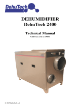 Dehutech 2400 User manual
-
Sierra Wireless Airlink MG90 User manual
-
Aerial AD 20 Condensation Dehumidifier User manual
-
Meaco DD8L-ZAMBEZI User manual
-
TrolMaster HS-1 Hydro-X Humidistat Station Operating instructions
-
Meaco DD8L User manual
-
-
-
Meaco MeacoDry ABC 10L, 12L and 20L User manual
-
Condair 52 Dehumidification Planning Owner's manual
