GA-P35C-DS3R/DS3/S3 Motherboard - 16 -
English
1-4 Installing the Memory
Read the following guidelines before you begin to install the memory:
• Make sure that the motherboard supports the memory. It is recommended that memory of
the same capacity, brand, speed, and chips be used.
(Go to GIGABYTE's website for the latest memory support list.)
• Always turn off the computer and unplug the power cord from the power outlet before
installing the memory to prevent hardware damage.
• Memory modules have a foolproof design. A memory module can be installed in only one
direction. If you are unable to insert the memory, switch the direction.
• Mixed mode, populating DDR2 and DDR3 memory modules simultaneously is not supported.
DDRII1
DDRII2
DDRII3
DDRII4
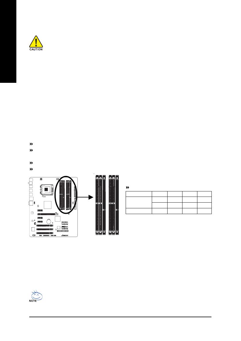
1-4-1 Dual Channel Memory Configuration
This motherboard provides four DDR2 and two DDR3 memory sockets and supports Dual Channel
Technology. After the memory is installed, the BIOS will automatically detect the specifications and
capacity of the memory. Enabling Dual Channel memory mode will double the original memory
bandwidth.
The four DDR2 memory sockets (DDRII1, DDRII2, DDRII3, and DDRII4) are divided into two channels
and each channel has two memory sockets as following:
Channel 0: DDRII1, DDRII2
Channel 1: DDRII3, DDRII4
The two DDR3 memory sockets (DDRIII1, DDRIII2) are divided into two channels as following:
Channel 0: DDRIII1
Channel 1: DDRIII2
DDR2 Dual Channel Memory Configuration:
Due to chipset limitation, read the following guidelines before installing the DDR2 memory in Dual Channel mode.
1. Dual Channel mode cannot be enabled if only one DDR2 memory module is installed.
2. When enabling Dual Channel mode with two or four memory modules, it is recommended that
memory of the same capacity, brand, speed, and chips be used and installed in the same
colored DDR2 sockets for optimum performance.
When memory modules of different capacity and chips are installed, a message which says
memory is operating in Flex Memory Mode will appear during the POST. Intel
®
Flex Memory
Technology offers greater flexibility to upgrade by allowing different memory sizes to be
populated and remain in Dual Channel mode/performance.
Two Modules
Four Modules
DDRII1 DDRII2 DDRII3 DDRII4
DS/SS - - DS/SS - -
- - DS/SS - - DS/SS
DS/SS DS/SS DS/SS DS/SS
DDR 2 Dual Channel Memory Configurations Table
(SS=Single-Sided, DS=Double-Sided, "- -"=No Memory)
DDRIII1
DDRIII2