Page is loading ...

TECHNICAL MANUAL
INSTALLATION MANUAL FOR EXPORT UNITS
SERVICE MANUAL FOR DOMESTIC UNITS
FOR JACKSON MODELS:
ELECTRIC HEATED
300X
300XLT
300XN
STEAM HEATED
300XS
Jackson MSC, Inc.
P.O. BOX 1060
HWY. 25E
BARBOURVILLE, KY. 40906
FAX (606) 523-9196
PHONE (606) 523-9795
www.jacksonmsc.com
UPRIGHT DOOR DISHMACHINE SERIES
July 26, 2006
P/N 7610-002-64-22 (Revision E)


i
REVISION
REVISION
DATE
MADE
BY
APPLICABLE
ECN
DETAILS
A 02-13-2003 MAW 6662 Release manual for service use.
B 07-11-2003 MAW
6652, 6681
6690
Updated per ecns.
C 02-09-2004 MAW 6973
Added 300XS Model. Changed Cover name from Service to
Technical.
D 02-10-2006 MAW
7205, 6964
7231, 7383
7553
Added 300XLT Dimensioned drawing. Changed High Limit
Thermostat from 05930-121-71-36 to 05930-011-49-43. Changed
Rinse Thermostat from 05930-121-71-29 to 05930-510-03-79.
Replace vacuum breaker 04820-300-07-00 with 04820-003-06-
13. Add false panel kit assembly numbers.
E 07-26-2006 MAW 7571
Converted to center layout. Added wash themostat kits and updat-
ed tub assemblies. Updated drain quench assembly.

ii
NOMENCLATURE FOR THE MODELS COVERED IN THIS MANUAL
300XS
300X = Electrically heated, high temp, hot water sanitizing, with booster heater, door-type dishmachine
300XLT = Electrically heated, low temp, chemical sanitizing, no rinse booster, door-type dishmachine
300XN = Electrically heated, high temp, hot water sanitizing, no rinse booster, door-type dishmachine
300XS = Steam heated, high temp, hot water sanitizing, door-type dishmachine
Model:
Serial No.:
Installation Date:
Service Rep. Name:
Phone No.:

SECTION DESCRIPTION PAGE
I. SPECIFICATION INFORMATION
Operating Capacities 2
Electrical Requirements 3
Dimensions 4
300XN/300XLT Dimensions 5
Table Dimensions 6
II. INSTRUCTION/OPERATION INSTRUCTIONS
Installation Instructions 8
300X System Flow Diagram 10
300XN/XLT System Flow Diagram 11
300XS System Flow Diagram 12
Detergent Control 13
Operation Instructions 14
III. PREVENTATIVE MAINTENANCE 17
IV. TROUBLESHOOTING SECTION 19
V. SERVICE PROCEDURES
Rinse Solenoid Valve Repair Parts Kit 22
Vacuum Breaker Repair Parts Kit 26
Rinse Regulating Thermostat Replacement 28
VI. PARTS SECTION
Control Box Assembly 33
Hood Assembly 35
Cantilever Arm/Door Assemblies 36
Frame Assembly 38
Tub Assembly 39
Steam Tub Assembly 41
RinseTank Assembly 43
Thermostats/Wash Heaters/Rinse Heaters 44
Wash Pump Exploded View 45
Wash Motors 46
Water Pressure Regulator Kit (WPRK) Option Plumbing 47
Incoming Plumbing Assembly 47
Outlet Plumbing Assembly 49
300XN/300XS Incoming Plumbing Assembly 50
Vacuum Breaker Repair Kit (1/2” NPT) 51
Solenoid Valve Repair Parts 51
300XS Incoming Steam Plumbing Assemblies 52
300XS Steam Coil Assembly 53
Wash and Rinse Arm/Manifold Assemblies 54
Safety Door Interlock (SDI) Option 56
Exhaust Fan Control Option 57
False Panel Kit Option 58
Drain Quench Kit Option 59
VII. ELECTRICAL DIAGRAMS
208V - 230V, 50/60 Hz, single/three phase 300X/XN/XLT 61
380V - 440V - 460V, 50/60 Hz, three phase 300X/XN/XLT 62
415V, 50/60 Hz, three phase 300X/XN/XLT 63
208V - 230V - 380V - 460V, 50/60 Hz, single/three phase 300XS 64
TABLE OF CONTENTS
i

1
SECTION 1:
SPECIFICATION INFORMATION

OPERATING CAPACITY (PER HOUR):
Model Racks Dishes Glasses
300X 57 1425 1425
300XN 57 1425 1425
300XLT 57 1425 1425
OPERATING CYCLE (SECONDS):
Wash Time 45 sec
Rinse Time 11 sec
Complete Cycle Time 58 sec
OPERATING TEMPERATURES (°F):
Wash Temperature (Minimum) 150°F
Wash Temperature (Minimum) 66°C
Rinse Temperature (Minimum) 180°F
Rinse Temperature (Minimum) 83°C
WATER REQUIREMENTS:
Inlet Temperature (300X/12KW Heater) (Minimum) 140°F
Inlet Temperature (300X/12KW Heater) (Minimum) 60°C
Inlet Temperature (300X/14KW Heater) (Minimum) 110°F
Inlet Temperature (300X/14KW Heater) (Minimum) 44°C
Inlet Temperature (300XN) (Minimum) 180°F
Inlet Temperature (300XN) (Minimum) 83°C
Inlet Temperature (300XLT) (Minimum) 110°F
Inlet Temperature (300XLT) (Minimum) 44°C
Gallons per Hour (Approximate) 52
Water Line Size 1/2” NPT
Drain Line Size 1-1/2” NPT
Flow Pressure PSI 20 A 5
Wash Tank Capacity (Gallons) 8
Wash Tank Capacity (Liters) 30.3
Rinse Tank Capacity (Gallons)(300X Only) 3
Rinse Tank Capacity (Gallons)(300X Only) 11.4
STEAM REQUIREMENTS:
COIL SIZE 3/4”
STEAM FLOW PRESSURE (P.S.I.) 10-20
CONSUMPTION @ 15 P.S.I. (LBS/HR) 45
NOTE: Always refer to the machine data plate for specific electrical and water requirements. The material provided on
this page is for reference only and may be subject to change without notice.
300X Series Technical Manual 7610-002-64-22
Issued: 07-26-2006 Revised: N/A
SECTION 1: SPECIFICATION INFORMATION
OPERATING CAPACITIES
2

300X Series Technical Manual 7610-002-64-22
Issued: 07-26-2006 Revised: N/A
SECTION 1: SPECIFICATION INFORMATION
ELECTRICAL REQUIREMENTS
300X
RINSE TYPICAL
HEATER TOTAL ELECTRICAL
VOLTS PH HZ RATINGS AMPS CIRCUIT
208 1 50 12 KW@240V 71 90 AMP
208 1 50 14 KW@240V 78 100 AMP
230 1 50 12 KW@240V 78 100 AMP
230 1 50 14 KW@240V 86 110 AMP
208 3 50 12 KW@240V 45 60 AMP
208 3 50 14 KW@240V 49 70 AMP
230 3 50 12 KW@240V 48 60 AMP
230 3 50 14 KW@240V 53 70 AMP
380 3 50 12 KW@380V 29 40 AMP
*380 3 50 14 KW@208V 34 45 AMP
415 3 50 12 KW@415V 26 35 AMP
415 3 50 14 KW@415V 29 40 AMP
440 3 50 12 KW@460V 21 30 AMP
440 3 50 14 KW@460V 25 35 AMP
208 1 60 12 KW@240V 69 90 AMP
208 1 60 14 KW@240V 76 100 AMP
230 1 60 12 KW@240V 76 100 AMP
230 1 60 14 KW@240V 84 110 AMP
208 3 60 12 KW@240V 43 60 AMP
208 3 60 14 KW@240V 47 60 AMP
230 3 60 12 KW@240V 46 60 AMP
230 3 60 14 KW@240V 51 70 AMP
460 3 60 12 KW@480V 22 30 AMP
460 3 60 14 KW@480V 24 30 AMP
300XN
RINSE TYPICAL
HEATER TOTAL ELECTRICAL
VOLTS PH HZ RATINGS AMPS CIRCUIT
208 1 50 N/A 28 35 AMP
230 1 50 N/A 30 40 AMP
208 3 50 N/A 20 25 AMP
230 3 50 N/A 21 30 AMP
380 3 50 N/A 10 15 AMP
415 3 50 N/A 10 15 AMP
440 3 50 N/A 8 15 AMP
208 1 60 N/A 26 35 AMP
230 1 60 N/A 28 35 AMP
208 3 60 N/A 18 25 AMP
230 3 60 N/A 28 35 AMP
460 3 60 N/A 8 15 AMP
300XLT
RINSE TYPICAL
HEATER TOTAL ELECTRICAL
VOLTS PH HZ RATINGS AMPS CIRCUIT
208 1 50 N/A 28 35 AMP
230 1 50 N/A 30 40 AMP
208 3 50 N/A 20 25 AMP
230 3 50 N/A 21 30 AMP
380 3 50 N/A 10 15 AMP
415 3 50 N/A 10 15 AMP
440 3 50 N/A 8 15 AMP
208 1 60 N/A 26 35 AMP
230 1 60 N/A 28 35 AMP
208 3 60 N/A 18 25 AMP
230 3 60 N/A 28 35 AMP
460 3 60 N/A 8 15 AMP
300XS
RINSE TYPICAL
HEATER TOTAL ELECTRICAL
VOLTS PH HZ RATINGS AMPS CIRCUIT
208 1 50 N/A 7 15 AMP
230 1 50 N/A 7 15 AMP
208 3 50 N/A 7 15 AMP
230 3 50 N/A 7 15 AMP
380 3 50 N/A 7 15 AMP
208 1 60 N/A 6 15 AMP
230 1 60 N/A 6 15 AMP
208 3 60 N/A 6 15 AMP
230 3 60 N/A 6 15 AMP
460 3 60 N/A 2 15 AMP
* This unit is wired in a wye configuration for the heaters.
3
NOTE: Typical Electrical Circuit is based upon (1) 125% of the full amperage load of the machine and (2) typical fixed-trip
circuit breaker sizes as listed in the NEC 2002 Edition. Local codes may require more stringent protection than what is dis-
played here. Always verify with your electrical service contractor that your circuit protection is adequate and meets all
applicable national and local codes. These numbers are provided in this manual simply for reference and may change with-
out notice at any given time.

300X Series Technical Manual 7610-002-64-22
Issued: 07-26-2006 Revised: N/A
SECTION 1: SPECIFICATION INFORMATION
300X DIMENSIONS
4
LEGEND:
A = Drain (1-1/2” NPT)
B = Water Inlet (1/2” NPT)
C = Electrical Connection
NOTE: All dimensions are in inches unless otherwise specified. All vertical dimensions are adjustable by +/- 1/2” (1.3 cm) due to
the adjustable bullet feet.

25 1/4"
4 1/2"
3 3/8"
32"
17 1/2"
1"
C
B
25 1/4"
4 1/2"
4 1/2"
4 7/8"
1"
B
C
17 1/2"
OPENING
76"
B
4 7/8"
13 3/8"
34"
TABLE HEIGHT
56 1/4"
64 3/8"
60 5/8"
61 3/4"
B
12 5/8"
300X Series Technical Manual 7610-002-64-22
Issued: 07-26-2006 Revised: N/A
SECTION 1: SPECIFICATION INFORMATION
300XN & 300XLT DIMENSIONS
5
LEGEND:
A = Drain (1-1/2” NPT)
B = Water Inlet (1/2” NPT)
C = Electrical Connection
NOTE: All dimensions are in inches unless otherwise specified. All vertical dimensions are adjustable by +/- 1/2” (1.3 cm) due
to the adjustable bullet feet.

300X Series Technical Manual 7610-002-64-22
Issued: 07-26-2006 Revised: N/A
SECTION 1: SPECIFICATION INFORMATION
TABLE DIMENSIONS
6
TABLE DIMENSIONS
CORNER INSTALLATION
TABLE DIMENSIONS
CONNECTION TO DISHMACHINE
TABLE DIMENSIONS
STRAIGHT THROUGH INSTALLATION
20 1/2” (52.1 cm)
OPENING
25 1/4”
(64.1 cm)
2 1/2” (6.4 cm)
4” (10.2 cm)
MINIMUM
2 1/2”
(6.4 cm)
4” (10.2 cm)
MINIMUM
20 1/2” (52.1 cm)
OPENING
25 1/4”
(64.1 cm)
20 1/2” (52.1 cm)
3/4” (1.9 cm)
1 1/2” (3.81 cm) ROLL
4” (10.2 cm)
MINIMUM
2 1/2”
(6.4 cm)
25 1/4”
(64.1 cm)
20 1/2” (52.1 cm)
OPENING
25 1/4” (64.1 cm)

7
SECTION 2:
INSTALLATION/OPERATION
INSTRUCTIONS

FOR SERVICE PERSONNEL: Jackson MSC Inc. provides technical support for all of the dishmachines detailed in this manu-
al. We strongly recommend that you refer to this manual before making a call to our technical support staff. Please have this
manual with you when you call so that our staff can refer you, if necessary, to the proper page. Technical support is available
from 8:00 a.m. to 5:00 p.m. (EST), Monday through Friday. Technical support is not available on holidays. Contact technical
support toll-free at 1-888-800-5672. Please remember that technical support is available for service personnel only. Non-ser-
vice personnel should refer to the list of provided service agencies in this manual for local service support.
VISUAL INSPECTION: Before installing the unit, check the container and machine for damage. A damaged container is an indi-
cator that there may be some damage to the machine. If there is damage to both the container and machine, do not throw away
the container. The dishmachine has been inspected and packed at the factory and is expected to arrive to you in new, undam-
aged condition. However, rough handling by carriers or others may result in there being damage to the unit while in transit. If
such a situation occurs, do not return the unit to Jackson; instead, contact the carrier and ask them to send a representative to
the site to inspect the damage to the unit and to complete an inspection report. You must contact the carrier within 48 hours of
receiving the machine. Also, contact the dealer through which you purchased the unit.
UNPACKING THE DISHMACHINE: Once the machine has been removed from the container, ensure that there are no miss-
ing parts from the machine. This may not be obvious at first. If it is discovered that an item is missing, contact Jackson imme-
diately to have the missing item shipped to you.
LEVEL THE DISHMACHINE: The dishmachine is designed to operate while being level. This is
important to prevent any damage to the machine during operation and to ensure the best results
when washing ware. The unit comes with adjustable bullet feet, which can be turned using a pair
of channel locks or by hand if the unit can be raised safely. Ensure that the unit is level from side
to side and from front to back before making any connections.
PLUMBING THE DISHMACHINE: All plumbing connections must comply with all applicable local,
state, and national plumbing codes. The plumber is responsible for ensuring that the incoming water line is thoroughly flushed
prior to connecting it to any component of the dishmachine. It is necessary to remove all foreign debris from the water line that
may potentially get trapped in the valves or cause an obstruction. Any valves that are fouled as a result of foreign matter left in
the water line, and any expenses resulting from this fouling, are not the responsibility of the manufacturer.
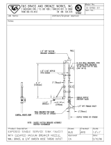
CONNECTING THE DRAIN LINE: The drain for the models covered in this manual are gravity discharge drains. All piping from
the 1 1/2” FNPT connection on the waste accumulator must be pitched (1/4” per foot) to the floor or sink drain. All piping from
the machine to the drain must be a minimum 1 1/2” NPT and shall not be reduced. There must also be an air gap between the
machine drain line and the floor sink or drain. If a grease trap is required by code, it should have a flow capacity of 5 gallons
per minute.
WATER SUPPLY CONNECTION: Ensure that you have read the section entitled
“PLUMBING THE DISHMACHINE” above before proceeding. Install the water supply
line (3/4” pipe size minimum) to the dishmachine line strainer using copper pipe. It is
recommended that a water shut-off valve be installed in the water line between the main
supply and the machine to allow access for service. The water supply line is to be capa-
ble of 20A5 PSI “flow” pressure at the recommended temperature indicated on the data
plate.
If the water level is too low or too high, check the incoming water pressure. It should be
20 A 5 PSI. Too high of pressure results in too much water; too low of pressure results
in too little water. To adust the regulator, loosen the nut at the top, this will allow you to
screw or unscrew the adjustment. With a screwdriver, turn the adjuster clockwise to
increase pressure or counter clockwise to decrease it.
In areas where the water pressure fluctuates or is greater than the recommended pres-
sure, it is recommended that a water pressure regulator be installed.
Do not confuse static pressure with flow pressure. Static pressure is the line pressure in a “no flow” condition (all valves and
services are closed). Flow pressure is the pressure in the fill line when the fill valve is opened during the cycle.
300X Series Technical Manual 7610-002-64-22
Issued: 07-26-2006 Revised: N/A
SECTION 2: INSTALLATION/OPERATION INSTRUCTIONS
INSTALLATION INSTRUCTIONS
8
Frame with Adjustable Foot
Raise
Lower
Incoming Plumbing Connection
Adjusting screw
Locking nut

It is also recommended that a shock absorber (not supplied with the models covered in this manual) be installed in the incom-
ing water line. This prevents line hammer (hydraulic shock), induced by the solenoid valve as it operates, from causing dam-
age to the equipment.
PLUMBING CHECK: Slowly turn on the water supply to the machine after the incoming fill line and the drain line have been
installed. Check for any leaks and repair as required. All leaks must be repaired prior to placing the machine in operation.
STEAM LINE CONNECTION: The 300XS is designed to use low pressure steam as a source of heat for wash tank water. The
machine comes with lines by which the source steam needs to be connected. Connect all steam lines to the machine as all
applicable codes provide. See machine data plate for information concerning steam flow pressure.
CHEMICAL DISPENSING EQUIPMENT: The 300XLT machine requires that a separate chemical feeder be connected to it to pro-
vide the required detergent and sanitizer. This feeder needs to be able to operate against a head of 25 PSI and provide 1.79 ml of
a 10% Chlorine sanitizer per minute.
ELECTRICAL POWER CONNECTION: Electrical and grounding connections must comply with the applicable portions of the
National Electrical Code ANSI/NFPA 70 (latest edition) and/or other electrical
codes.
Disconnect electrical power supply and place a tag at the disconnect switch to
indicate that you are working on the circuit.
The dishmachine data plate is located on the right side and to the front of the
machine. Refer to the data plate for machine operating requirements, machine
voltage, total amperage load and serial number.
To install the incoming power lines, open the control box. This will require taking
a phillips head screwdriver and removing the one(1) screw on the front cover of
the control box. Install 3/4” conduit into the pre-punched holes in the back of the
control box. Route power wires and connect to power block and grounding lug.
Install the service wires (L1, L2 & L3 (3 phase models only.)) to the appropriate
terminals as they are marked on the terminal block. Install the grounding wire
into the lug provided.
It is recommended that “DE-OX” or another similar anti-oxidation agent be used on all power connections.
VOLTAGE CHECK: Ensure that the power switch is in the OFF position and apply power to the dishmachine. Check the incom-
ing power at the terminal block and ensure it corresponds to the voltage listed on the data plate. If not, contact a qualified ser-
vice agency to examine the problem. Do not run the dishmachine if the voltage is too high or too low. Shut off the service break-
er and mark it as being for the dishmachine. Advise all proper personnel of any problems and of the location of the service
breaker. Replace the control box cover and tighten down the screws.
300X Series Technical Manual 7610-002-64-22
Issued: 07-26-2006 Revised: N/A
SECTION 2: INSTALLATION/OPERATION INSTRUCTIONS
INSTALLATION INSTRUCTIONS (CONTINUED)
9
Terminal Block Ground Lug
Electrical Connection

300X Series Technical Manual 7610-002-64-22
Issued: 07-26-2006 Revised: N/A
SECTION 2: INSTALLATION/OPERATION INSTRUCTIONS
300X SYSTEM FLOW DIAGRAM
10
S
WASH TANK HEATER
RINSE ARM
RINSE BOOSTER TANK
RINSE BOOSTER HEATER
Y-STRAINER
PRESSURE
REGULATING
VALVE
RINSE
SOLENOID
VALVE
VACUUM
BREAKER
PRESSURE
GAUGE
DISHMACHINE
WATER TREATMENT
CARTRIDGE IF
INSTALLED
FROM BUILDING
WATER SUPPLY
All items found within the dotted region are found
within the footprint of the machine.

300X Series Technical Manual 7610-002-64-22
Issued: 07-26-2006 Revised: N/A
SECTION 2: INSTALLATION/OPERATION INSTRUCTIONS
300XN/XLT SYSTEM FLOW DIAGRAM
11
S
RINSE ARM
VACUUM
BREAKER
PRESSURE
GAUGE
RINSE
SOLENOID
VALVE
WASH TANK HEATER
PRESSURE
REGULATING
VALVE
Y-STRAINER
WATER TREATMENT
CARTRIDGE IF
INSTALLED
FROM BUILDING
WATER SUPPLY

300X Series Technical Manual 7610-002-64-22
Issued: 07-26-2006 Revised: N/A
SECTION 2: INSTALLATION/OPERATION INSTRUCTIONS
300XS SYSTEM FLOW DIAGRAM
12
S
S
STEAM
TRAP
STEAM COILS
VACUUM
BREAKER
PRESSURE
GAUGE
RINSE
SOLENOID
VALVE
STEAM
SOLENOID
VALVE
Y-STRAINER
MANUAL
SHUTOFF
VALVE
PRESSURE
REGULATING
VALVE
Y-STRAINER
EXTERNAL STEAM BOOSTER
BUILDING
STEAM
SUPPLY
BUILDING
STEAM
RETURN
WATER TREATMENT
CARTRIDGE (IF
INSTALLED)
BUILDING
WATER
SUPPLY
BUILDING
STEAM
SUPPLY
BUILDING
STEAM
RETURN
All items found within the dotted region are found
within the footprint of the machine.
Steam plumbing should be assembled and connected
to the steam booster in accordance with the steam
booster manufacturer’s instructions and applicable
codes.

Detergent usage and water hardness are two factors that contribute greatly to how efficiently your dishmachine will operate.
Using detergent in the proper amount can become, in time, a source of substantial savings. A qualified water treatment spe-
cialist can tell you what is needed for maximum efficiency from your detergent, but you should still know some basics so you’ll
understand what they are talking about.
First, you must understand that hard water greatly effects the performance of the dishmachine. Water hardness is the amount
of dissolved calcium and magnesium in the water supply. The more dissolved solids in the water, the greater the water hard-
ness. Hard water works against detergent, thereby causing the amount of detergent required for washing to increase. As you
use more detergent, your costs for operating the dishmachine will increase and the results will decrease. The solids in hard
water also may build-up as a scale on wash and rinse heaters, decreasing their ability to heat water. Water temperature is
important in removing soil and sanitizing dishes. If the water cannot get hot enough, your results may not be satisfactory. This
is why Jackson recommends that if you have installed the machine in an area with hard water, that you also install some type
of water treatment equipment to help remove the dissolved solids from the water before it gets to the dishmachine.
Second, hard water may have you adding drying agents to your operating cycle to prevent spotting, when the real problem is
deposited solids on your ware. As the water evaporates off of the ware, the solids will be left behind to form the spotting and
no amount of drying agent will prevent this. Again, using treated water will undoubtedly reduce the occurrences of this prob-
lem.
Third, treated water may not be suitable for use in other areas of your operation. For instance, coffee made with soft water may
have an acid or bitter flavor. It may only be feasible to install a small treatment unit for the water going into the dishmachine
itself. Discuss this option with your qualified water treatment specialist.
Even after the water hardness problems have been solved, there still must be proper training of dishmachine operators in how
much detergent is to be used per cycle. Talk with your water treatment specialist and detergent vendor and come up with a
complete training program for operators. Using too much detergent has as detrimental effects as using too little. The proper
amount of detergent must be used for job. It is important to remember that certain menu items may require extra detergent by
their nature and personnel need to be made aware of this. Experience in using the dishmachine under a variety of conditions,
along with good training in the operation of the machine, can go a long way in ensuring your dishmachine operates as effi-
ciently as possible.
Certain dishmachine models require that chemicals be provided for proper operation and sanitization. Some models even
require the installation of third-party chemical feeders to introduce those chemicals to the machine. Jackson does not recom-
mend or endorse any brand name of chemicals or chemical dispensing equipment. Contact your local chemical distributor for
questions concerning these subjects.
Some dishmachines come equipped with integral solid detergent dispensers. These dispensers are designed to accommodate
detergents in a certain sized container. If you have such a unit, remember to explain this to your chemical distributor upon first
contacting them.
As explained before, water temperature is an important factor in ensuring that your dishmachine functions properly. The data
plate located on each unit details what the minimum temperatures must be for either the incoming water supply, the wash tank
and the rinse tank, depending on what model of dishmachine you have installed. These temperatures may also be followed by
temperatures that Jackson recommends to ensure the highest performance from you dishmachine. However, if the minimum
requirements are not met, the chances are your dishes will not be clean or sanitized. Remember, a dish can look clean, but it
may not be sanitized. Instruct your dishmachine operators to observe the required temperatures and to report when they fall
below the minimum allowed. A loss of temperature can indicate a much larger problem such as a failed heater or it could also
indicate that the hot water heater for your operation is not up to capacity and a larger one may need to be installed.
There are several factors to consider when installing your dishmachine to ensure that you get the best possible results from it
and that it operates at peak efficiency for many years. Discuss your concerns with your local chemical distributor and water
treatment specialist before there is a problem.
300X Series Technical Manual 7610-002-64-22
Issued: 07-26-2006 Revised: N/A
SECTION 2: INSTALLATION/OPERATION INSTRUCTIONS
DETERGENT CONTROL
13

300X Series Technical Manual 7610-002-64-22
Issued: 07-26-2006 Revised: N/A
SECTION 2: INSTALLATION/OPERATION INSTRUCTIONS
OPERATION INSTRUCTIONS
14
PREPARATION: Before proceeding with the start-up of the unit, verify the following:
1. The pump intake, and wash tank strainers are in place and is clean.
2. The drain stopper is installed.
3. That the wash and rinse arms are screwed securely into place and that their endcaps are tight. The wash and rinse arms should
rotate freely.
POWER UP: To energize the unit, turn on the power at the service breaker. The voltage should have been previously verified as
being correct. If not, the voltage will have to be verified. Verify that the gas supply to the machine is on as well.
FILLING THE WASH TUB: Ensure that the delime switch is in the NORMAL position, and place the power switch into the ON posi-
tion. The models covered in this manual should fill automatically and shut off when the appropriate level is reached (the gas burn-
ers should also automatically ignite as well). Verify that the drain stopper is preventing the wash tub water from pouring out exces-
sively. There will probably be some slight leakage from the drain hole. Verify that there are no other leaks on the unit before pro-
ceeding any further. The wash tub must be completely filled before operating the wash pump to prevent damage to the compo-
nent. Once the wash tub is filled, the unit is ready for operation.
The water level was set at the factory. If the water level is not at the level noted above, it will require adjustment. Check to ensure
that the recommended water pressure is being supplied to the machine (20A5 PSI). If the water pressure is correct then the fill
valve will need adjustment.
WARE PREPARATION: Proper preparation of ware will help ensure good results and less re-washes. If not done properly, ware
may not come out clean and the efficiency of the dishmachine will be reduced. It is important to remember that a dishmachine is
not a garbage disposal and that simply throwing unscraped dishes into the machine simply defeats the purpose altogether of wash-
ing the ware. Scraps should be removed from ware prior to being loaded into a rack.
Pre-rinsing and pre-soaking are recommended, especially for silverware and casserole dishes. Place cups and glasses upside
down in racks so that they do not hold water during the cycle. The dishmachine is meant not only to clean, but to sanitize as well,
to destroy all of the bacteria that could be harmful to human beings. In order to do this, ware must be properly prepared prior to
being placed in the machine.
DAILY MACHINE PREPARATION: Refer to the section entitled “PREPARATION” at the top of this page and follow the instructions
there. Afterwards, check that all of the chemical levels are correct and/or that there is plenty of detergent available for the expect-
ed workload.
WARM-UP CYCLES: For a typical daily start-up, it is recommended to run the machine through 3 cycles to ensure that all of the
cold water is out of the system and to verify that the unit is operating correctly. To cycle the machine, ensure that the power is on
and that the tub has filled to the correct level. Lift the doors and the cycle light will illuminate. When the light goes out, close the
doors, the unit will start, run through the cycle, and shut off automatically. Repeat this two more times. The unit should now be
ready to proceed with the washing of ware.
WASHING A RACK OF WARE: To wash a rack, open the doors completely (being careful for hot water that may drip from the
doors) and slide the rack into the unit. Close the doors and the unit will start automatically. Once the cycle is completed, open the
door (again watching for the dripping hot water) and remove the rack of clean ware. Replace with a rack of soiled ware and close
the doors. The process will then repeat itself.
OPERATIONAL INSPECTION: Based upon usage, the wash tank strainer may become clogged with soil and debris as the work-
day progresses. Operators should regularly inspect the wash tank strainer to ensure it has not become clogged. If the strainer
does, it will reduce the washing capability of the machine. Instruct operators to clean out the wash tank strainer at regular intervals
or as required by work load.

300X Series Technical Manual 7610-002-64-22
Issued: 07-26-2006 Revised: N/A
SECTION 2: INSTALLATION/OPERATION INSTRUCTIONS
OPERATION INSTRUCTIONS (CONTINUED)
15
SHUTDOWN AND CLEANING: At the end of the workday, close the doors. When the unit completes the cycle, turn the power
switch to the OFF position and open the doors. Manually remove the drain stopper from the tub and allow the tub to drain (NOTE:
the wash tank water will be hot so caution is advised). Once the wash tub is drained, remove the wash tank strainer and the pump
suction strainer. Remove soil and debris from the strainer and set to the side. Unscrew the wash and rinse arms from their mani-
folds. Remove the endcaps and flush the arms with water. Use a brush to clean out the inside of the arms. If the nozzles appear
to be clogged, use a toothpick to remove the obstruction. Wipe the inside of the unit out, removing all soil and scraps. Reassemble
the wash and rinse arms and replace them in the unit. The arms only need to be hand tight, do not use tools to tighten them down.
Reinstall the strainers and close the doors.
This equipment is not recommend for use with deionized water or other aggressive fluids. Use of deionized
water or other aggressive fluids will result in corrosion and failure of materials and components. Use of deion-
ized water or other aggressive fluids will void the manufacturer's warranty.
/