Troy-Bilt 23AAAA8X711 User manual
- Category
- Lawnmowers
- Type
- User manual
This manual is also suitable for

TROY-BILT LLC, P.O. BOX 361131 CLEVELAND, OHIO 44136-0019
Printed In USA
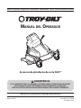
OperatOr’s Manual
Safe Operation Practices • Set-Up • Operation • Maintenance • Service • Troubleshooting • Warranty
WARNING
READ AND FOLLOW ALL SAFETY RULES AND INSTRUCTIONS IN THIS MANUAL
BEFORE ATTEMPTING TO OPERATE THIS MACHINE.
FAILURE TO COMPLY WITH THESE INSTRUCTIONS MAY RESULT IN PERSONAL INJURY.
FLEX™ Mower Deck Attachment
Form No. 769-10252B
(July 23, 2019)

Customer Support
Please do NOT return the machine to the retailer or dealer without first contacting the Customer Support Department.
If you have difficulty assembling this product or have any questions regarding the controls, operation, or maintenance of
this machine, you can seek help from the experts. Choose from the options below:
◊ Visit us on the web at www.troybilt.com
See How-to Maintenance and Parts Installation Videos at www.troybilt.com/tutorials
◊ Call a Customer Support Representative at (800) 828-5500 or (330) 558-7220
◊ Write to Troy-Bilt LLC • P.O. Box 361131 • Cleveland, OH • 44136-0019
Thank you for purchasing the Troy-Bilt FLEX™ Mower Deck
Attachment. It was carefully engineered to provide excellent
performance when properly operated and maintained.
Please read this entire manual prior to operating the equipment.
It instructs you how to safely and easily set up, operate and
maintain your machine. Please be sure that you, and any other
persons who will operate the machine, carefully follow the
recommended safety practices at all times. Failure to do so could
result in personal injury or property damage.
All information in this manual is relative to the most recent
product information available at the time of printing. Review
this manual frequently to familiarize yourself with the machine,
its features and operation. Please be aware that this Operator’s
Manual may cover a range of product specifications for various
models. Characteristics and features discussed and/or illustrated
in this manual may not be applicable to all models. We reserve
the right to change product specifications, designs and
equipment without notice and without incurring obligation.
If you have any problems or questions concerning the machine,
phone an authorized Troy-Bilt service dealer or contact us
directly. Troy-Bilt’s Customer Support telephone numbers,
website address and mailing address can be found on this page.
We want to ensure your complete satisfaction at all times.
Throughout this manual, all references to right and left side of the
machine are observed from the operating position
Thank You
Record Product Information
Before setting up and operating your new equipment, please
locate the model plate on the equipment and record the
information in the provided area to the right. You can locate
the model plate by looking at the rear mounting assembly on
the mowing attachment, when the unit is NOT coupled with
the base unit. This information will be necessary, should you
seek technical support via our web site, Customer Support
Department, or with a local authorized service dealer.
Model NuMber
Serial NuMber
To The Owner
1
2
Safe Operation Practices ........................................ 3
Controls & Features ................................................. 8
Operation ................................................................. 9
Maintenance & Adjustment .................................12
Service .....................................................................14
Troubleshooting .....................................................18
Replacement Parts .................................................19
Warranty ................................................................ 20
Table of Contents

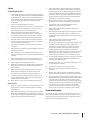
Important Safe Operation Practices
2
3
General Operation
1. Read this operator’s manual carefully in its entirety before
attempting to assemble this machine. Read, understand,
and follow all instructions on the machine and in the
manual(s) before operation. Keep this manual in a safe
place for future and regular reference and for ordering
replacement parts.
2. Be completely familiar with the controls and the proper use
of this machine before operating it.
3. This machine is a precision piece of power equipment,
not a plaything. Therefore, exercise extreme caution at all
times. This machine has been designed to perform one job:
to mow grass. Do not use it for any other purpose.
4. Never allow children under 14 years of age to operate this
machine. Children 14 and over should read and understand
the instructions and safe operation practices in this manual
and on the machine and should be trained and supervised
by an adult.
5. Only responsible individuals who are familiar with these
rules of safe operation should be allowed to use this
machine.
6. Thoroughly inspect the area where the equipment is to be
used. Remove all stones, sticks, wire, bones, toys and other
foreign objects, which could be tripped over or picked up
and thrown by the blade. Thrown objects can cause serious
personal injury.
7. Plan your mowing pattern to avoid discharge of material
toward roads, sidewalks, bystanders and the like. Also,
avoid discharging material against a wall or obstruction,
which may cause discharged material to ricochet back
toward the operator.
8. To help avoid blade contact or a thrown object injury,
stay in operator zone behind handles and keep children,
bystanders, helpers and pets at least 75 feet from mower
while it is in operation. Stop machine if anyone enters area.
9. Always wear safety glasses or safety goggles during
operation and while performing an adjustment or repair
to protect your eyes. Thrown objects which ricochet can
cause serious injury to the eyes.
10. Wear sturdy, rough-soled work shoes and close-fitting
slacks and shirts. Shirts and pants that cover the arms
and legs and steel-toed shoes are recommended. Never
operate this machine in bare feet, sandals, slippery or light-
weight (e.g. canvas) shoes.
11. Do not put hands or feet near rotating parts or under the
cutting deck. Contact with blade can amputate fingers,
hands, toes and feet.
12. A missing or damaged discharge cover can cause blade
contact or thrown object injuries.
13. Many injuries occur as a result of the mower being pulled
over the foot during a fall caused by slipping or tripping.
WARNING: This symbol points out important safety instructions which, if not followed,
could endanger the personal safety and/or property of yourself and others. Read and follow
all instructions in this manual before attempting to operate this machine. Failure to comply
with these instructions may result in personal injury.
When you see this symbol. HEED ITS WARNING!
DANGER: This machine was built to be operated according to the safe operation practices in
this manual. As with any type of power equipment, carelessness or error on the part of the
operator can result in serious injury. This machine is capable of amputating fingers, hands,
toes and feet and throwing objects. Failure to observe the following safety instructions could
result in serious injury or death.
CALIFORNIA PROPOSITION 65
WARNING: Engine Exhaust, some of its constituents, and certain vehicle components
contain or emit chemicals known to State of California to cause cancer and birth defects
or other reproductive harm.
WARNING: Battery posts, terminals, and related accessories contain lead and lead
compounds, chemicals known to the State of California to cause cancer and reproductive
harm. Wash hands after handling.

4 Section 2 — important Safe operation practiceS
Do not hold on to the mower if you are falling; release the
Drive and Attachment Control Levers immediately.
14. Never pull the mower back toward you while you are
walking. If you must back the mower away from a wall or
obstruction first look down and behind to avoid tripping
and then follow these steps:
a. Step back from mower to fully extend your arms.
b. Be sure you are well balanced with sure footing.
c. Pull the mower back slowly, no more than half way
toward you.
d. Repeat these steps as needed.
15. Do not operate the mower while under the influence of
alcohol or drugs.
16. Do not engage the self-propelled mechanism while
starting the engine.
17. The blade control is a safety device. Never attempt to
bypass its operation. Doing so makes the safety device
inoperative and may result in personal injury through
contact with the rotating blade. The blade control must
operate easily in both directions and automatically return
to the disengaged position when released.
18. Never operate the mower in wet grass. Always be sure of
your footing. A slip and fall can cause serious personal
injury. If you feel you are losing your footing, release the
Attachment Control Lever immediately and the blade will
stop rotating within three (3) seconds.
19. Mow only in daylight or good artificial light. Walk, never
run.
20. Stop the blade when crossing gravel drives, walks or roads.
21. If the equipment should start to vibrate abnormally, stop
the engine and check immediately for the cause. Vibration
is generally a warning of trouble.
22. Shut the engine off and wait until the blade comes to
a complete stop before removing the grass catcher or
unclogging the chute. The cutting blade continues to
rotate for a few seconds after the blade control is released.
Never place any part of the body in the blade area until you
are sure the blade has stopped rotating.
23. Never operate mower without proper trail shield,
discharge cover, grass catcher, blade control or other safety
protective devices in place and working. Never operate
mower with damaged safety devices. Failure to do so can
result in personal injury.
24. Muffler and engine become hot and can cause a burn. Do
not touch.
25. Never attempt to make a wheel or cutting height
adjustment while the engine is running.
26. Only use parts and accessories made for this machine by
the manufacturer. Failure to do so can result in personal
injury.
27. When starting engine, pull cord slowly until resistance
is felt, then pull rapidly. Rapid retraction of starter cord
(kickback) will pull hand and arm toward engine faster than
you can let go. Broken bones, fractures, bruises or sprains
could result.
28. If situations occur which are not covered in this manual, use
care and good judgement. Contact Customer Support for
assistance or the name of the nearest service dealer.
Slope Operation
Slopes are a major factor related to slip and fall accidents, which
can result in severe injury. Operation on slopes requires extra
caution. If you feel uneasy on a slope, do not mow it. Make sure
you are able to control the machine. For your safety, use the
slope gauge included as part of this manual to measure slopes
before operating this machine on a sloped or hilly area. If the
slope is greater than 10 degrees, do not mow it.
Do:
1. Mow across the face of slopes; never up and down. Exercise
extreme caution when changing direction on slopes.
2. Watch for holes, ruts, rocks, hidden objects, or bumps
which can cause you to slip or trip. Tall grass can hide
obstacles.
3. Always be sure of your footing. A slip and fall can cause
serious personal injury. If you feel you are losing your
balance, release the Attachment Control Lever immediately
and the blade will stop rotating within three (3) seconds.
Do Not:
1. Do not mow near drop-offs, ditches or embankments, you
could lose your footing or balance.
2. Do not mow slopes greater than 10 degrees as shown on
the slope gauge.
3. Do not mow on wet grass. Unstable footing could cause
slipping.
Children
Tragic accidents can occur if the operator is not alert to the
presence of children. Children are often attracted to the mower
and the mowing activity. They do not understand the dangers.
Never assume that children will remain where you last saw them.
1. Keep children out of the mowing area and under watchful
care of a responsible adult other than the operator.
2. Be alert and turn mower off if a child enters the area.
3. Before and while moving backwards, look behind and
down for small children.
4. Use extreme care when approaching blind corners,
doorways, shrubs, trees, or other objects that may obscure
your vision of a child who may run into the mower.
5. Keep children away from hot or running engines. They can
suffer burns from a hot muffler.
6. Never allow children under 14 years of age to operate this
machine. Children 14 and over should read and understand
the instructions and safe operation practices in this manual
and on the machine and be trained and supervised by an
adult.
7. After stopping engine, remove ignition key and keep it in a
safe place out of the reach of children.

5Section 2 — important Safe operation practiceS
Service
Safe Handling Of Gasoline:
1. To avoid personal injury or property damage use extreme
care in handling gasoline. Gasoline is extremely flammable
and the vapors are explosive. Serious personal injury can
occur when gasoline is spilled on yourself or your clothes,
which can ignite. Wash your skin and change clothes
immediately.
2. Use only an approved gasoline container.
3. Never fill containers inside a vehicle or on a truck or trailer
bed with a plastic liner. Always place containers on the
ground away from your vehicle before filling.
4. Remove gas-powered equipment from the truck or
trailer and refuel it on the ground. If this is not possible,
then refuel such equipment on a trailer with a portable
container, rather than from a gasoline dispenser nozzle.
5. Keep the nozzle in contact with the rim of the fuel tank or
container opening at all times until fueling is complete. Do
not use a nozzle lock-open device.
6. Extinguish all cigarettes, cigars, pipes and other sources
of ignition.
7. Never fuel machine indoors because flammable vapors will
accumulate in the area.
8. Never remove gas cap or add fuel while engine is hot or
running. Allow engine to cool at least two minutes before
refueling.
9. Never over fill fuel tank. Fill tank to no more than 1 inch
below bottom of filler neck to provide for fuel expansion.
10. Replace gasoline cap and tighten securely.
11. If gasoline is spilled, wipe it off the engine and equipment.
Move machine to another area. Wait 5 minutes before
starting engine.
12. Never store the machine or fuel container near an open
flame, spark or pilot light as on a water heater, space
heater, furnace, clothes dryer or other gas appliances.
13. To reduce fire hazard, keep machine free of grass, leaves,
or other debris build-up. Clean up oil or fuel spillage and
remove any fuel soaked debris.
14. Allow machine to cool at least 5 minutes before storing.
General Service:
1. Never run an engine indoors or in a poorly ventilated area.
Engine exhaust contains carbon monoxide, an odorless
and deadly gas.
2. Before cleaning, repairing, or inspecting, make certain the
blade and all moving parts have stopped. Disconnect the
spark plug wire and ground against the engine and remove
Ignition Key to prevent unintended starting.
3. Check the blade and engine mounting bolts at frequent
intervals for proper tightness. Also, visually inspect blade
for damage (e.g., bent, cracked, worn) Replace blade with
the original equipment manufacture’s (O.E.M.) blade only,
listed in this manual. “Use of parts which do not meet the
original equipment specifications may lead to improper
performance and compromise safety!”
4. Mower blades are sharp and can cut. Wrap the blade or
wear gloves, and use extra caution when servicing them.
5. Keep all nuts, bolts, and screws tight to be sure the
equipment is in safe working condition.
6. Never tamper with safety devices. Check their proper
operation regularly.
7. After striking a foreign object, stop the engine, and remove
the ignition key. Thoroughly inspect the mower for any
damage. Repair the damage before starting and operating
the mower.
8. Never attempt to make a wheel or cutting height
adjustment while the engine is running.
9. Grass catcher components, discharge cover, and trail shield
are subject to wear and damage which could expose
moving parts or allow objects to be thrown. For safety
protection, frequently check components and replace
immediately with original equipment manufacturer’s
(O.E.M.) parts only, listed in this manual. “Use of parts which
do not meet the original equipment specifications may
lead to improper performance and compromise safety!”
10. Do not change the engine’s governor setting or over-speed
the engine. The governor controls the maximum safe
operating speed of the engine.
11. Check fuel line, tank, cap, and fittings frequently for cracks
or leaks. Replace if necessary.
12. Do not crank engine with spark plug removed.
13. Maintain or replace safety and instruction labels, as
necessary.
14. Observe proper disposal laws and regulations. Improper
disposal of fluids and materials can harm the environment.
15. According to the Consumer Products Safety Commission
(CPSC) and the U.S. Environmental Protection Agency (EPA),
this product has an Average Useful Life of seven (7) years,
or 140 hours of operation. At the end of the Average Useful
Life have the machine inspected annually by an authorized
service dealer to ensure that all mechanical and safety
systems are working properly and not worn excessively.
Failure to do so can result in accidents, injuries or death.
Do not modify engine
To avoid serious injury or death, do not modify engine in any
way. Tampering with the governor setting can lead to a runaway
engine and cause it to operate at unsafe speeds. Never tamper
with factory setting of engine governor.

6 Section 2 — important Safe operation practiceS
WARNING: Your Responsibility—Restrict the use of this power machine to persons who read, understand and
follow the warnings and instructions in this manual and on the machine.
SAVE THESE INSTRUCTIONS!
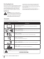
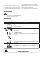
Safety Symbols
This page depicts and describes safety symbols that may appear on this product. Read, understand, and follow all instructions on the
machine before attempting to assemble and operate.
Symbol Description
READ THE OPERATOR’S MANUAL(S)
Read, understand, and follow all instructions in the manual(s) before attempting to
assemble and operate
DANGER — ROTATING BLADES
Do not operate unless an undamaged discharge cover or entire grass catcher is in place. If
damaged, replace immediately.
DANGER — BYSTANDERS
Do not mow when children or others are around. Look behind while backing.
DANGER — HAND/ FOOT CUT
Keep hands and feet away from moving parts.
DANGER — THROWN DEBRIS
Remove objects that can be thrown by the blade in any direction. Wear safety glasses.
MAX 10
DANGER — SLOPES
Use extra caution on slopes. Do not mow slopes greater than 10°.
Notice Regarding Emissions
Engines which are certified to comply with California and federal
EPA emission regulations for SORE (Small Off Road Equipment)
are certified to operate on regular unleaded gasoline, and
may include the following emission control systems: Engine
Modification (EM), Oxidizing Catalyst (OC), Secondary Air
Injection (SAI) and Three Way Catalyst (TWC) if so equipped.
Spark Arrestor
WARNING: This machine is equipped with an
internal combustion engine and should not be used
on or near any unimproved forest-covered, brush
covered or grass-covered land unless the engine’s
exhaust system is equipped with a spark arrestor
meeting applicable local or state laws (if any).
If a spark arrestor is used, it should be maintained in effective
working order by the operator. In the State of California the
above is required by law (Section 4442 of the California Public
Resources Code). Other states may have similar laws. Federal laws
apply on federal lands.
A spark arrestor for the muffler is available through your
nearest engine authorized service dealer or contact the Service
Department, P.O. Box 361131 Cleveland, Ohio 44136-0019.

7Section 2 — important Safe operation practiceS
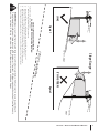
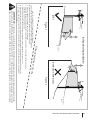
(OK) (TOO STEEP)
USE THIS SLOPE GAUGE TO DETERMINE
IF A SLOPE IS TOO STEEP FOR SAFE OPERATION!
To check the slope, proceed as follows:
1. Remove this page and fold along the dashed line.
2. Locate a vertical object on or behind the slope (e.g. a pole, building, fence, tree, etc.)
3. Align either side of the slope gauge with the object (See Figure 1 and Figure 2 ).
4. Adjust gauge up or down until the left corner touches the slope (See Figure 1 and Figure 2).
5. If there is a gap below the gauge, the slope is too steep for safe operation (See Figure 2 above).
10°/17% dashed line
Slope Gauge
Figure 2Figure 1
10°/17% Slope
10°/17%
Slope
WARNING! Slopes are a major factor related to tip-over and roll-over accidents which can result in severe injury or death.
Do not operate machine on slopes in excess of 10 degrees or 17 percent. All slopes require extra caution. If you feel uneasy
on it, do not mow it. Always mow across the face of slopes, never mow up and down slopes.

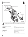
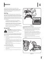
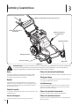
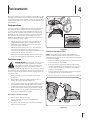
Controls & Features
3
8
Discharge Chute
Mulch Plug
Grease Fitting
Drive Control Lever
Attachment Control Lever
Attachment Control Lever Lock
Deck Lift Lever
Caster Wheel Lock
Figure 3-1
WARNING! Read and follow all safety rules and instructions in this manual, including the entire Operation
section, before attempting to operate this machine. Failure to comply with all safety rules and instructions
may result in personal injury.
Engine
Refer to the FLEX™ Base Unit Operator’s Manual for details
regarding all engine-related controls and features.
Caster Wheel
The front caster wheels may be locked in a forward position,
or unlocked with the ability to swivel based on the operator’s
control of the handle system.
Caster Wheel Lock
The caster lock is located on the top of each front caster wheel.
Grease Fitting
Used to lubricate the caster wheel swivel function.
Deck Lift Lever
Used to control the mowing heighth of the cutting deck.
Mulch Plug
Can be used when the discharge chute or optional bagger
attachment is NOT installed.
Discharge Chute
The discharge chute is located on the right side of the mower
attachment and controls the dispersion of grass clippings.
Drive Control Lever
This lever propels the entire machine forward.
Attachment Control Lever
This lever engages the cutting deck, allowing the blades to spin.

Operation
4
9
Thank you for purchasing the Troy-bilt FLEX™ mower
attachment. This unit is fully assembled and requires no setup.
The following instructions will guide you through use and
operation of your new attachment, along with maintenance
instructions and procedures.
Mulch Plug
The Troy-bilt FLEX™ mowing attachment is equipped with a
mulch plug and special blades already installed on your mowing
attachment as standard equipment, which recirculate the grass
clippings repeatedly beneath the cutting deck. The ultra-fine
clippings are then forced back into the lawn where they act as a
natural fertilizer. Observe the following points for the best results
when mulching:
• Do NOT attempt to mulch if the lawn is damp. Wet
grass tends to stick to the underside of the cutting deck
preventing proper mulching of the clippings.
• Do NOT attempt to mulch more than ⁄ the total height of
the grass. Doing so will cause the clippings to clump up
beneath the deck and not be mulched effectively.
• Maintain a slow ground speed to allow the grass clippings
more time to effectively be mulched.
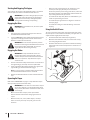
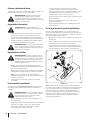
Discharge Chute
WARNING! Before installing or removing the
discharge chute, disengage blades, stop the engine
and remove key if so equipped to prevent
unintended starting.
A side discharge chute has been included with this attachment
in the event the operator wishes to discharge rather than mulch
the grass clippings. To install the side discharge chute, follow
these instructions:
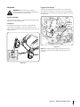
1. Stop the engine and wait for all parts to stop moving.
2. Pivot the mulch plug upwards, exposing the hinge mount.
See Figure 4-1.
3. With the side discharge chute pivoted upwards, hook the
tabs on the discharge chute under the hinge pin, as shown
in the inset of Figure 4-1, and pivot the discharge chute
downward and into place.
Note: The mulch plug will rest on top of the discharge
chute, and retain it in place.
To remove the discharge chute:
1. Pivot the mulch plug upwards.
2. Lift the side discharge chute upwards and away from the
mowing deck.
3. Allow the mulch plug to pivot back downward into place.
Figure 4-1
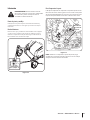
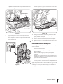
Connecting With The FLEX™ Base Unit
NOTE: All references to the left or right side of the jet sweep blower
are from the operator’s position. Any exceptions will be noted.
1. Roll the FLEX™ Base Unit over to the mounting position
with the FLEX™ mower attachment.
2. With the kickstand down, roll the power unit forward,
engaging the top part of the mowing attachment with the
handle mount provide on the power unit (1 of Figure 4-2).
3. Tip the FLEX™ Base Unit backwards to engage the two
bottom connection points mounts (2).
4. Put the kickstand up and the two units are now locked
together.
1
2
Figure 4-2

10 Section 4— operation
Starting And Stopping The Engine
Start and stop the engine on the FLEX™ Base Unit in accordance
with the operator’s manual included with that machine.
WARNING! If you strike a foreign object, stop the
engine and remove the ignition key. Thoroughly
inspect the machine for any damage. Repair the
damage before restarting and operating
Engaging the Drive
WARNING! Avoid sudden starts, excessive speed
and sudden stops.
1. Start the engine as instructed in the operator’s manual
included with the Power Base Unit.
2. To travel FORWARD, slowly squeeze the Drive Control lever
against the handle grip and the unit will move forward.
Release it and drive motion will stop.
WARNING! Do not leave the operator’s position
without first releasing the Attachment Control Lever.
If leaving the mower unattended, also turn the
engine off and remove the ignition key.
Engaging the Blades
WARNING! To help avoid blade contact or a
thrown object injury, keep bystanders, helpers,
children and pets at least 75 feet from the machine
while it is in operation. Stop machine if anyone
enters the area.
1. Push in and hold the safety release button on the inside of
the right hand grip, until Step 2 has been performed.
2. Slowly squeeze the Attachment Control Lever against the
right handle grip and the blades will engage.
Note: It is not necessary to hold the safety release button
once the Attachment Control Lever is activated.
3. Release the Attachment Control Lever and the blades will
stop.
Operating On Slopes
Refer to the SLOPE GAUGE on page 5 to help determine slopes
where you may operate the mower safely.
WARNING! Do not mow on inclines with a slope in
excess of 10 degrees (a rise of approximately 2 feet
every 10 feet). The mower could overturn and cause
serious injury.
• Mow across the face of slopes; never up and down.
• Exercise extreme caution when changing direction on
slopes.
• Watch for holes, ruts, rocks, hidden objects, or bumps
which can cause you to slip or trip. Tall grass can hide
obstacles.
• Always be sure of your footing. A slip and fall can cause
serious personal injury. Be sure you can control the
machine. If you feel you are losing your balance, release the
Attachment Control Lever immediately and the blades will
stop rotating within three (3) seconds:
• Do not mow near drop-offs, ditches or embankments, you
could lose your footing or balance.
• Do not mow slopes greater than 10 degrees as shown on
the slope gauge.
• Do not mow on wet grass. Unstable footing could cause
slipping.
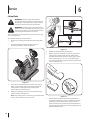
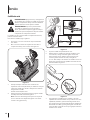
Using the Deck Lift Lever
To raise or lower the cutting deck, move the deck lift lever to the
left, then place it in the notch best suited for your application. To
adjust the deck height, follow these steps:
1. Pivot the deck lift lever outward (1 in Figure 4-3).
2. Move the lever forward to lower, and rearward to raise (2)
the cutting height of the deck.
3. Allow the deck lift lever to pivot back towards the mowing
attachment and into the locked position as shown in 3 of
Figure 4-3.
1
2
3
Figure 4-3

11Section 4 — operation
Note: When moving the deck lift lever up and down, the front
caster wheels must also be adjusted to coordinate with the deck
lift lever. If the deck lift lever is moved into the lowest cutting
position, then the front caster wheels must be moved into the
highest hole adjustment. Follow this guideline when adjusting
the deck height. See Figure 4-4 for reference.
Figure 4-4
Mowing
The following information will be helpful when operating your
mower.
WARNING! Plan your mowing pattern to avoid
discharge of materials toward roads, sidewalks,
bystanders and the like. Also, avoid discharging
material against a wall or obstruction which may
cause discharged material to ricochet back toward
the operator.
• Do not cut the grass too short. Short grass is prone to weed
growth and yellows quickly in dry weather.
• For best results, it is recommended that the first two laps
be cut with the discharge thrown towards the center.
After the first two laps, reverse the direction to throw the
discharge to the outside for the balance of cutting. This will
give a better appearance to the lawn.
• Do NOT attempt to mow heavy brush and weeds or
extremely tall grass. Your mower is designed to mow lawns,
NOT clear brush.
• Keep the blades sharp and replace the blades when worn.
WARNING! After striking a foreign object, stop the
engine, disconnect the spark plug wire and ground
against the engine. Thoroughly inspect the mower
for any damage. Repair the damage before starting
and operating the mower.
Front Wheel Pivot Lock
The two front wheels of the mowing attachment include both a
free-pivoting feature used for steering the unit around objects,
and a locking feature for mowing in a straight line or across
slopes (never up and down slopes).
To lock and unlock the front wheels:
1. Pull up on the locking rod, as shown in Figure 4-5.
2. Move the locking rod outward to and align with the hole
provided to lock the wheels in a straight ahead position.
See Figure 4-5.
3. Move the locking rod inward to align with the hole
provided to allow the wheels to free pivot, enabling
steering around objects.
Figure 4-5

Maintenance
WARNING! Before performing any maintenance or
repairs, disengage blades, stop engine and remove
key to prevent unintended starting.
Engine
Refer to the FLEX™ Base Unit Owner’s Manual for all engine
maintenance procedures and specific instructions pertaining to
your engine.
Cleaning the Mower
Any fuel or oil spilled on the machine should be wiped off
promptly. Do NOT allow debris to accumulate around any part of
the machine, especially the belts and pulleys.
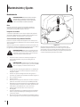
Deck Wash
This mowing attachment is equipped with a water port on its
deck surface as part of a deck wash system.
Use the deck wash to rinse grass clippings from the deck’s
underside and prevent the buildup of corrosive chemicals.
Complete the following steps AFTER EACH MOWING:
WARNING! Before using the deck wash system,
always disengage the Attachment Control Lever,
stop engine and remove key to prevent unintended
starting.
1. Position the mower on a level, clear spot on your lawn, near
enough for your garden hose to reach.
CAUTION: Make certain the mower’s discharge
chute is attached and directed AWAY from your
house, garage, parked cars, etc.
2. Thread the hose coupler (packaged with the mowing
attachment’s Operator’s Manual) onto the end of your
garden hose.
3. Attach the hose coupler to the water port onto your deck’s
surface. See Figure 5-1.
4. Turn the water on.
5. Start the engine.
6. While in the operator’s position behind the mower, move
the Attachment Control Lever into the ON position.
7. Remain in the operator’s position with the cutting deck
engaged for a minimum of two minutes, allowing the
underside of the cutting deck to thoroughly rinse.
8. Move the Attachment Control Lever into the OFF position.
9. Move the On/Off switch on the FLEX™ Base Unit to the OFF
position to turn the mower’s engine off.
10. Turn the water off and detach the hose coupler from the
water port on your deck’s surface.
Figure 5-1
After cleaning your deck with the deck wash system, start the
mower’s engine, return to the operator’s position and engage
the blades. Keep the cutting deck running for a minimum of
two minutes, allowing the underside of the cutting deck to
thoroughly dry.
Maintenance & Adjustments
5
12

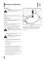
Lubrication
WARNING! Before lubricating, repairing, or
inspecting, always stop the engine and remove the
key to prevent unintended starting.
Pivot Points & Linkage
Lubricate all the pivot points on the drive system and lift linkage
at least once a season with light oil.
Front Wheels
Each of the front wheel axles and casters is equipped with
a grease fitting. See Figure 5-2. Lubricate with a No. 2 multi-
purpose grease applied with a grease gun after every 25 hours of
mower operation.
Figure 5-2
Engagement Pivot Bracket
Lubricate the engagement pivot bracket once a season with a
spray lubricant. See Figure 5-3. In order to access this pivot point,
refer to Belt Care in the Service section for the steps for removing
the belt covers.
Apply
lubricant at
this pivot
point
Figure 5-3
NOTE: When lubricating the engagement pivot bracket, be
careful not to get any oil on the belts. Wipe off any excess or
spilled oil.
13Section 5 — Maintenance & adjuStMentS

Service
6
14
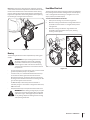
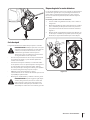
Cutting Blades
WARNING! Shut the engine off and remove
ignition key before removing the cutting blades for
sharpening or replacement. Protect your hands by
using heavy gloves when grasping the blades.
WARNING! Periodically inspect the blade and/or
spindle for cracks or damage, especially after you’ve
struck a foreign object. Do not operate the machine
until damaged components are replaced.
The cutting blades can be sharpened or replaced. To do so, they
must be removed first.
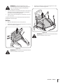
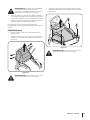
To remove the blades, proceed as follows:
1. Disconnect the mowing attachment from the FLEX™ Base
Unit.
2. Pivot the mowing attachment backwards onto its
mounting assembly, as shown in Figure 6-1.
Figure 6-1
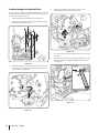
3. Place a block of wood between the center deck housing
baffle and the cutting blade to prevent the blade from
turning when loosening the blade’s hex flange nut.
See the left-hand side of Figure 6-2.
4. Remove the hex flange nut that secures the blade to the
spindle assembly. See Figure 6-2.
Note: The hex flange nut is secured using a standard thread
pattern. Turn counter-clockwise to loosen.
Figure 6-2
5. Remove the blades from the mowing deck.
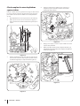
6. Replace or sharpen the blades. To properly sharpen the
cutting blades, remove equal amounts of metal from
both ends of the blades along the cutting edges, parallel
to the trailing edge, at a 25° to 30° angle. Always grind
each cutting blade edge equally to maintain proper blade
balance. See Figure 6-3.
Figure 6-3
7. Test the blades for balance by balancing the blade on a
round shaft screwdriver to check. If out of balance, when
sharpening, remove metal from the heavy side until it
balances evenly. During sharpening the blade, follow the
original angle of grind. Grind each cutting edge equally to
keep the blade balanced.

15Section 6 — Service
WARNING: An unbalanced blade will cause
excessive vibration when rotating at high speeds. It
may cause damage to mower and could break
causing personal injury.
8. Slide the blade onto the spindle shaft with the side marked
“Bottom” (or with part number) facing the ground when
the mower is in the operating position.
9. Replace the hex bolt and tighten to torque: 450 in. lbs. min.,
600 in. lbs. max.
To ensure safe operation of your mower, periodically check the
blade bolt for correct torque.
Belt Care
1. Move the deck lift lever into its center position.
2. Remove the top belt cover by removing the five screws that
secure it as shown in Figure 6-4.
Figure 6-4
WARNING! Never operate this attachment without
either one of these covers in place.
3. Remove the lower belt cover by removing the four screws
that secure it as shown in Figure 6-5.
Figure 6-5
WARNING! Never operate this attachment without
either one of these covers in place.

16 Section 6 — Service
To replace the upper and lower deck belts:
Three belt keepers must first be removed, followed by removal of
the upper, then lower belts. Follow these steps to service either
or both of the mowing deck belts:
1. Lower mowing deck to the lowest cutting position.
2. Remove the belt keeper shown in Figure 6-6 by removing
the four hex screws that secure it.
Figure 6-6
3. Remove the belt keeper secured to the vertical portion of
the mowing deck attachment by removing the hex screw
that secures it. See Figure 6-7.
Figure 6-7
4. Remove the left belt keeper shown in Figure 6-8 by
removing the two hex screws that secure it.
Figure 6-8
5. Loosen, but do not remove, the idler pulley used on the top
deck belt.
6. Remove the cotter pin from the height adjustment link, and
slide the link off of the height adjustment pivot assembly.
See Figure 6-9.
Figure 6-9

17Section 6 — Service
7. Remove the top belt from the drive spindle by working the
belt around the spindle pulley as shown in Figure 6-10.
Spindle Pulley
Figure 6-10
8. Using the attachment handle, pull up on the mowing deck
attachment to create a larger gap between the drive pulley
and frame, easing removal of the top belt from around the
drive pulley. Refer to Figure 6-11.
Figure 6-11
9. Relieve tension on the lower belt by moving the idler arm
and tension pulley inward as shown in Figure 6-12.
Figure 6-12
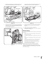
10. Remove the lower belt by working it off of the image left
pulley above first, then the other pulley and off of the
machine.
11. Replace the lower belt, then the upper belt.
12. Repeat Steps 1 through 9 in the reverse order to complete
the belt replacement process.
Off-Season Storage
The following steps should be taken to prepare your lawn mower
for storage.
• Clean and lubricate mower thoroughly as described in the
lubrication instructions.
• Do not use a pressure washer or garden hose to clean your
unit.
• Coat mower’s cutting blade with chassis grease to prevent
rusting.
• Refer to Engine Maintenance section in the FLEX™ Base
Unit manual for correct engine storage instructions.
• Store mower in a dry, clean area. Do not store next to
corrosive materials, such as fertilizer.
When storing any type of power equipment in a poorly
ventilated or metal storage shed, care should be taken to
rust-proof the equipment. Using a light oil or silicone, coat the
equipment, especially cables and all moving parts of your lawn
mower before storage.

Troubleshooting
7
18
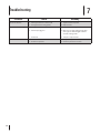
Problem Cause Remedy
Excessive vibration 1. Cutting blade loose or unbalanced.
2. Damaged or bent cutting blade.
1. Tighten blade and spindle.
2. Replace blade.
Mower will not mulch grass 1. Wet grass.
2. Excessively high grass.
3. Dull blade.
1. Do not mulch when grass is wet.
2. Mow once at a high cutting height, then
mow again at desired height or make a
narrower cutting swath.
3. Sharpen or replace blade.
Uneven cut 1. Dull blade.
2. Uneven tire pressure.
1. Sharpen or replace blade.
2. Check tire pressure in rear tires.

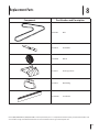
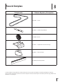
Replacement Parts
8
19
Component Part Number and Description
954-05103 Belt
942-05130 Deck Blade
634-04606 Wheel
731-10510 Discharge Chute
687-05133 Mulch Plug
731-10534A Trail Shield
Phone (800) 828-5500 or (330) 558-7220 to order replacement parts or a complete Parts Manual (have your full model number and
serial number ready). Parts Manual downloads are also available free of charge at www.troybilt.com.

LIMITED WARRANTY FOR FLEX ATTACHMENT PRODUCT
079221 REV. D
6. Any Attachment that has been altered or modified in a manner not
consistent with the original design of the product or in a manner not
otherwise approved by Troy-Bilt LLC.
7. Paint repairs or replacements for defective paint (including materials
and application) are covered for a period of three (3) months.
8. Where applicable, wheel rims are covered for a period of three (3)
months for manufacturing defects.
9. Log splitter pumps, valves, and cylinders are covered for a period of
one (1) year.
10. The FLEX Power Base is covered by a separate limited warranty which
is contained in the operator’s manual for the FLEX Power Base.
This warranty does not cover and Troy-Bilt LLC disclaims any
responsibility for:
1. Loss of time or loss of use of the Attachment.
2. Transportation costs and other expenses incurred in connection with
the transport of the Attachment to and from the authorized Troy-Bilt
service provider.
3. Any loss or damage to other equipment or personal items.
4. Damage caused by performance or use of the Attachment in
connection with any product other than the FLEX Power Base.
Limitations:
1. THERE ARE NO IMPLIED WARRANTIES, INCLUDING, BUT NOT LIMITED
TO, ANY IMPLIED WARRANTY OF MERCHANTABILITY OR FITNESS FOR A
PARTICULAR PURPOSE. NO WARRANTY APPLIES AFTER THE APPLICABLE
WARRANTY PERIOD AS SET FORTH ABOVE AS TO THE PARTS AS
IDENTIFIED. NO OTHER EXPRESS WARRANTY OR GUARANTY, WHETHER
WRITTEN OR ORAL, EXCEPT AS MENTIONED ABOVE, GIVEN BY ANY
PERSON OR ENTITY, INCLUDING A DEALER OR RETAILER, WITH RESPECT
TO ANY PRODUCT SHALL BIND TROY-BILT LLC. DURING THE WARRANTY
PERIOD, THE EXCLUSIVE REMEDY IS REPAIR OR REPLACEMENT OF THE
DEFECTIVE PART, AS SET FORTH ABOVE. (SOME STATES DO NOT ALLOW
LIMITATIONS ON HOW LONG AN IMPLIED WARRANTY LASTS, SO THE
ABOVE LIMITATION MAY NOT APPLY TO YOU.)
2. THE PROVISIONS AS SET FORTH HEREIN PROVIDE THE SOLE AND
EXCLUSIVE REMEDY ARISING FROM THE SALE. TROY-BILT SHALL NOT
BE LIABLE FOR INCIDENTAL OR CONSEQUENTIAL LOSS OR DAMAGES
INCLUDING, WITHOUT LIMITATION, FOR TRANSPORTATION OR FOR
RELATED EXPENSES, OR FOR RENTAL EXPENSES TO TEMPORARILY
REPLACE A WARRANTED PRODUCT. (SOME STATES DO NOT ALLOW
THE EXCLUSION OR LIMITATION OF INCIDENTAL OR CONSEQUENTIAL
DAMAGES, SO THE ABOVE EXCLUSION OR LIMITATION MAY NOT APPLY
TO YOU.)
3. In no event shall recovery of any kind be greater than the amount of the
purchase price of the product sold. Alteration of the safety features of the
product shall void this limited warranty. You assume the risk and liability
for loss, damage, or injury to you and your property and/or to others
and their property arising out of the use or misuse or inability to use the
product.
4. Subject to the Exclusions, this limited warranty extends to the
Initial Purchaser and to a succeeding owner of the Attachment
for non-commercial use for the duration of the Warranty Period,
beginning from the original date of purchase by the Initial Purchaser
of such Attachment. Subject to the Exclusions, in the event that the
original date of purchase by the Initial Purchaser of the Attachment is
indeterminable, the Warranty Period shall be established as twenty
eight (28) months from the Attachment’s date of manufacture, as
determined by Troy-Bilt. In no event shall an Attachment’s warranty
extend beyond the established Warranty Period.
How State Law Relates to this Warranty:
This limited warranty gives you specific legal rights, and you may also have
other rights which vary from state to state.
Troy-Bilt LLC, P.O. BOX 361131 CLEVELAND, OHIO 44136-0019; Phone: 1-800-828-5500, 1-330-558-7220
MTD Canada Limited - KITCHENER, ON N2G 4J1; Phone 1-800-668-1238
The limited warranty set forth herein is given by Troy-Bilt LLC to the Initial
Purchaser (as defined herein) with respect to a new Troy-Bilt-branded FLEX
attachment product consisting of either a (i) wide area mower, (ii) snow-
thrower, (iii) pressure washer, (iv) leaf blower, (v) dethatcher, (vi), aerator, (vii)
water pump, (viii) chipper/shredder, or (ix) log splitter (referred to hereafter
as the “Attachment”) to be used with the FLEX Power Base. This limited
warranty does not cover Emission Control Systems and is not a Federal
Emission Control Warranty Statement as defined by U.S. federal law. Please
refer to the Federal Emission Control Warranty Statement in the operator’s
manual for the FLEX Power Base product (“Power Base”) for warranties
covering Emission Control Systems.
Scope of the Limited Warranty
Troy-Bilt LLC offers the following limited warranty to the Initial Purchaser for
residential or otherwise non-commercial use of the Attachment on the FLEX
Power Base: except for the Exclusions (defined herein), during the Warranty
Period (defined herein), the Attachment will be free from manufacturing
defects (including workmanship and materials). The “Initial Purchaser” is the
first person to purchase a new Attachment from an authorized Troy-Bilt dealer,
distributor and/or retailer of such attachment products. This limited warranty
is non-transferrable. Except as otherwise set forth herein, the limited warranty
period for this new Attachment purchased by the Initial Purchaser is two (2)
years from the date of purchase as shown on the original sales receipt for the
Attachment (“Warranty Period”).
Defects in Workmanship or Materials
Except for the Exclusions, the Attachment is warranted to be free from
manufacturing defects in either workmanship or materials for the Warranty
Period. During the Warranty Period, Troy-Bilt LLC will, at its option, either
repair or replace any original part that is covered by this limited warranty and
is determined to be defective in workmanship or material.
To qualify for this limited warranty the Attachment:
1. Must have been purchased from an authorized Troy-Bilt retailer.
2. Must have been purchased within the United States by the Initial
Purchaser.
3. Must have been used for residential or otherwise non-commercial
purposes.
4. Must have been used in a manner consistent with the normal and
proper intended use for the Attachment. This Attachment is not
intended for rental or commercial use.
Who can perform repairs under this warranty?
In order to qualify for the limited warranty as set forth herein, the repairs made
under this warranty must be performed by an authorized Troy-Bilt service
provider.
How to get service under this limited warranty:
To locate a Troy-Bilt warranty service provider, contact your authorized
Troy-Bilt dealer, distributor and/or retailer or contact Troy-Bilt LLC at P.O. Box
361131, Cleveland, Ohio 44136-0019 or call 1-877-282-8684 or log on to our
Website at www.troybilt.com. This limited product warranty is provided
by Troy-Bilt LLC and is the only product warranty provided by Troy-Bilt LLC
for this Attachment. A COPY OF YOUR SALES RECEIPT IS REQUIRED FOR
WARRANTY SERVICE.
What this limited warranty does not cover.
This limited warranty does not cover the following (the “Exclusions”):
1. Attachment purchased outside of the United States.
2. Damage due to lack of maintenance and/or improper maintenance as
described in the operator’s manual.
3. Normal wear and tear resulting from use of the Attachment.
4. Use of the Attachment that is not consistent with the intended use
thereof as described in the operating instructions, including, but not
limited to, abuse, misuse and/or neglect of the Attachment or any use
inconsistent with and/or non-compliant with instructions contained in
the Operator’s Manual.
5. Any expendable, consumable, or routine maintenance item which
needs replacement or service as part of normal maintenance, unless
such items have defects that cause failure or premature wear within
the first thirty (30) days. Where applicable, normal wear items include
but are not limited to, blades, tires, belts, filters, fuses, hoses, where
applicable, and other consumable items.
Page is loading ...
Page is loading ...
Page is loading ...
Page is loading ...
Page is loading ...
Page is loading ...
Page is loading ...
Page is loading ...
Page is loading ...
Page is loading ...
Page is loading ...
Page is loading ...
Page is loading ...
Page is loading ...
Page is loading ...
Page is loading ...
Page is loading ...
Page is loading ...
Page is loading ...
Page is loading ...
-
 1
1
-
 2
2
-
 3
3
-
 4
4
-
 5
5
-
 6
6
-
 7
7
-
 8
8
-
 9
9
-
 10
10
-
 11
11
-
 12
12
-
 13
13
-
 14
14
-
 15
15
-
 16
16
-
 17
17
-
 18
18
-
 19
19
-
 20
20
-
 21
21
-
 22
22
-
 23
23
-
 24
24
-
 25
25
-
 26
26
-
 27
27
-
 28
28
-
 29
29
-
 30
30
-
 31
31
-
 32
32
-
 33
33
-
 34
34
-
 35
35
-
 36
36
-
 37
37
-
 38
38
-
 39
39
-
 40
40


Troy-Bilt 23AAAA8X711 User manual
- Category
- Lawnmowers
- Type
- User manual
- This manual is also suitable for
Ask a question and I''ll find the answer in the document
Finding information in a document is now easier with AI
in other languages
Related papers
-
Troy-Bilt 23AAAA8X711 User manual
-
Troy-Bilt 12ACC3BJ766 User manual
-
-
-
-
Troy-Bilt 12AKD39C211 User manual
-
-
-
-
Other documents
-
Craftsman CMXGMAM201202 Owner's manual
-
Yard-Man 430 Series User manual
-
Troybilt V560 Owner's manual
-
 Craftsman ProSeries 39790 Owner's manual
-
MTD Series 410 User manual
-
-
Cub Cadet 997 Owner's manual
-
Bolens 544 User manual
-
MTD 680 User manual
-
Yard-Man 829 Series User manual
