LG DLEX2550V Owner's manual
- Category
- Electric laundry dryers
- Type
- Owner's manual

OWNER’S MANUAL
DRYER
DLEX2550* DLGX2551*
DLEX2450* DLGX2451*
DLEX2650* DLGX2651*
DLEX2655* DLGX2656*
Please read this manual carefully before operating
your dryer and retain it for future reference.
P/No. MFL67408112
www.lg.com
ENGLISH
FRANÇAIS

IMPORTANT SAFETY INSTRUCTIONS
What to Do if You Smell Gas .................................. 3
Basic Safety Precautions ....................................... 4
California Safe Drinking Water and Toxic
Enforcement Act ................................................... 4
Grounding Instructions ...........................................5
Safety Instructions for Installation ..........................5
Safety Instructions for Steam Functions ................6
Safety Instructions for Connecting Electricity .......7
Congratulations on your purchase
and welcome to the LG family. Your
new LG Dryer combines the most
advanced drying sensor technol-
ogy with simple operation and high
efficiency.
Follow the operating and care in-
structions in this manual and your
dryer will provide many years of reli-
able service
THANK YOU!
INSTALLATION INSTRUCTIONS
Installation Location Requirements ..................... 10
Clearances ........................................................... 10
Installation With Optional
Pedestal Base or Stacking Kit .............................. 11
Leveling the Dryer ................................................ 12
Optional Accessories .......................................... 12
To Remove the Door ............................................ 13
To Install the Door ............................................... 14
Changing the Dryer Vent Location ....................... 15
Venting the Dryer .................................................. 16
Connecting Gas Dryers ........................................ 18
Connecting Electric Dryers .................................. 20
Special Requirements for Manufactured
or Mobile Homes ................................................. 25
Final Installation Check ....................................... 25
Installation Test (Exhaust check) ......................... 26
HOW TO USE
Control Panel Features ........................................ 28
Operating the Dryer ............................................. 29
Cycle Guide ......................................................... 30
Sorting Loads ...................................................... 3 1
Loading the Dryer ................................................ 3 1
Check the Lint Filter Before Every Load .............. 3 1
The Display .......................................................... 32
Cycle Setting Buttons .......................................... 33
Special Functions ................................................ 34
Custom Program ................................................. 35
Steam Functions .................................................. 35
Steam Cycle Guide .............................................. 37
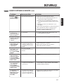
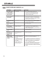
TROUBLESHOOTING
Regular Cleaning ................................................ 38
Before Calling for Service ....................................39
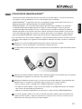
Using SmartDiagnosis
TM
.......................................42
PARTS AND FEATURES
Special Features ..................................................... 8
Key Parts and Components ................................... 9
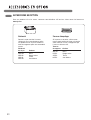
OPTIONAL ACCESSORIES
Optional Accessories ........................................... 43
Pedestal Installation ............................................. 44
Stacking Kit Installation ........................................ 46
SPECIFICATIONS
Key Dimensions and Specifications ..................... 47
WARRANTY ................................................... 48
2

ENGLISH
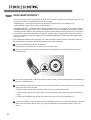
1. Do not try to light a match or cigarette,
or turn on any gas or electrical
appliance.
2. Do not touch any electrical switches.
Do not use any phone in your building.
3. Clear the room, building, or area of all
occupants.
4. Immediately call your gas supplier
from a neighbor’s phone. Follow the
gas supplier’s instructions carefully.
5. If you cannot reach your gas
supplier, call the fire department.
WHAT TO DO IF YOU SMELL GAS:
3
READ ALL INSTRUCTIONS BEFORE USE
Your Safety and the safety of others is very important.
We have provided many important safety messages in this manual and on your appliance. Always read
and obey all safety messages.
This is the safety alert symbol.
This symbol alerts you to potential hazards that can kill or hurt you and others.
All safety messages will follow the safety alert symbol and either the word DANGER or WARNING.
These words mean:
wDANGER: You can be killed or seriously injured if you don’t immediately follow instructions.
wWARNING: You can be killed or seriously injured if you don’t follow instructions.
All safety messages will tell you what the potential hazard is, tell you how to reduce the chance of
injury, and tell you what can happen if the instructions are not followed.
•Donotinstallaclothesdryerwith
flexible plastic venting materials. If
flexible metal (foil type) duct is in-
stalled, it must be of a specific type
identified by the appliance manufac-
turer as suitable for use with clothes
dryers. Flexible venting materials are
known to collapse, be easily crushed,
and trap lint. These conditions will
obstruct clothes dryer airflow and
increase the risk of fire.
•Donotstoreorusegasolineorother
flammable vapors and liquids in the
vicinity of this appliance or any other
appliances.
•Installationandservicemustbe
performed by a qualified installer,
service agency, or the gas supplier.
•Installtheclothesdryeraccordingto
the manufacturer’s instructions and
local codes.
•Savetheseinstructions.
wWARNING For your safety, the information in this manual must be
followed to minimize the risk of fire or explosion, electric shock, or to prevent
property damage, injury to persons , or death.

READ ALL INSTRUCTIONS BEFORE USE
wWARNING
For your safety, the information in this manual must be
followed to minimize the risk of fire or explosion, electric shock, or to prevent
property damage, injury to persons , or death.
CALIFORNIA SAFE DRINKING WATER AND TOXIC ENFORCEMENT ACT
This act requires the governor of California to publish a list of substances known to the state to cause
cancer, birth defects, other reproductive harm and requires businesses to warn customers of potential
exposure to such substances.
Gas appliances can cause minor exposure to four of these substances, namely benzene, carbon monoxide,
formaldehyde, and soot, caused primarily by the incomplete combustion of natural gas or LP fuels.
Properly adjusted dryers will minimize incomplete combustion. Exposure to these substances can be
minimized further by properly venting the dryer to the outdoors.
BASIC SAFETY PRECAUTIONS
wWARNING: To reduce the risk of fire, electric shock, or injury to persons when using this
appliance, follow basic precautions, including the following:
•Readallinstructionsbeforeusingthedryer.
•Beforeuse,thedryermustbeproperlyinstalled
as described in this manual.
•Donotplaceitemsexposedtocookingoilsin
your dryer. Items contaminated with cooking
oils may contribute to a chemical reaction that
could cause a load to catch fire.
•Donotdryarticlesthathavebeenpreviously
cleaned in, washed in, soaked in, or spotted
with gasoline, dry-cleaning solvents, or other
flammable or explosive substances as they give
off vapors that could ignite or explode.
•Donotreachintothedryerifthedrumorany
other part is moving.
•Donotrepairorreplaceanypartofthedryer
or attempt any servicing unless specifically
recommended in this Use and Care Guide or
in published user-repair instructions that you
understand and have the skills to carry out.
•Donottamperwithcontrols.
•Beforethedryerisremovedfromserviceor
discarded, remove the door to the drying
compartment.
•Donotallowchildrentoplayonorinthedryer.
Close supervision of children is necessary when
the dryer is used near children.
•Donotusefabricsoftenersorproductsto
eliminate static unless recommended by the
manufacturer of the fabric softener or product.
•Donotuseheattodryarticlescontaining
foam rubber or similarly textured rubber-like
materials.
•Keepareaaroundtheexhaustopeningand
adjacent surrounding areas free from the
accumulation of lint, dust, and dirt.
•Theinteriorofthedryerandexhaustvent
should be cleaned periodically by qualified
service personnel.
•Donotinstallorstorethedryerwhereitwillbe
exposed to the weather.
•Alwayschecktheinsideofthedryerforforeign
objects.
•Cleanlintscreenbeforeoraftereachload.
•Donotstoreplastic,paper,orclothingthat
may burn or melt on top of the dryer during
operation.
4

ENGLISH
GROUNDING INSTRUCTIONS
This appliance must be grounded. In the event
of malfunction or breakdown, grounding will
reduce the risk of electric shock by providing
a path of least resistance for electric current.
This appliance must be equipped with a cord
having an equipment-grounding conductor and
a grounding plug. The plug must be plugged into
an appropriate outlet that is properly installed and
grounded in accordance with all local codes and
ordinances.
Do not modify the plug provided with the
appliance. If it will not fit the outlet, have a proper
outlet installed by a qualified electrician.
This appliance must be connected to a grounded
metal, permanent wiring system or an equipment-
grounding conductor must be run with the circuit
conductors and connected to the equipment-
grounding terminal or lead on the appliance.
Electric shock can result if the dryer is not
properly grounded.
wWARNING — Improper connection of the equipment-grounding conductor can result
in a risk of electric shock. Check with a qualified electrician or service person if you are in doubt that the
appliance is properly grounded.
5
READ ALL INSTRUCTIONS BEFORE USE
SAFETY INSTRUCTIONS FOR INSTALLATION
•Properly ground dryer to conform with all
governing codes and ordinances. Follow
details in the installation instructions. Electric
shock can result if the dryer is not properly
grounded.
•Before use, the dryer must be properly
installed as described in this manual. Electric
shock can result if the dryer is not properly
grounded.
•Install and store the dryer where it will not be
exposed to temperatures below freezing or
exposed to the weather.
•All repairs and servicing must be performed
by an authorized servicer unless specifically
recommended in this Owner’s Guide. Use
only authorized factory parts. Failure to follow
this warning can cause serious injury, fire,
electric shock, or death.
•To reduce the risk of electric shock, do not
install the dryer in humid spaces. Failure to
follow this warning can cause serious injury, fire,
electric shock, or death.
wWARNING For your safety, the information in this manual must be
followed to minimize the risk of fire or explosion, electric shock, or to prevent
property damage, injury to persons , or death.
wWARNING: To reduce the risk of fire, electric shock, or injury to persons when using this
appliance, follow basic precautions, including the following:
•Connect to a properly rated, protected,
and sized power circuit to avoid electrical
overload. Improper power circuit can melt,
creating electric shock and/or fire hazard.
•Remove all packing items and dispose of all
shipping materials properly. Failure to do so
can result in death, explosion, fire, or burns.
•Place dryer at least 18 inches above the floor
for a garage installation. Failure to do so can
result in death, explosion, fire, or burns.
•Keep all packaging from children. Packaging
material can be dangerous for children. There is
a risk of suffocation.
•Do not install near another source of heat
such as a stove, cooking oven. Failure to do
so can cause deform, smoke and fire.
•Do not place candles, smoking materials,
or other flammables on top of the product.
Dripping wax, smoke, or fire can result.
•Remove all protective vinyl film from the
product. Failure to do so can cause product
damage, smoke or fire.

6
READ ALL INSTRUCTIONS BEFORE USE
SAFETY INSTRUCTIONS FOR INSTALLATION
wWARNING For your safety, the information in this manual must be
followed to minimize the risk of fire or explosion, electric shock, or to prevent
property damage, injury to persons, or death.
Exhaust/Ducting:
•GasdryersMUSTbeexhaustedtothe
outside. Failure to follow these instructions
can result in fire or death.
•The dryer exhaust system must be exhausted
to the outside of the dwelling. If the dryer is
not exhausted outdoors, some fine lint and
large amounts of moisture will be expelled
into the laundry area. An accumulation of
lint in any area of the home can create a health
and fire hazard.
•Use only rigid metal or flexible metal 4-inch
diameter ductwork inside the dryer cabinet
or for exhausting to the outside. Use of
plastic or other combustible ductwork can
cause a fire. Punctured ductwork can cause
a fire if it collapses or becomes otherwise
restricted in use or during installation.
•Ductwork is not provided with the dryer, and
you should obtain the necessary ductwork
locally. The end cap should have hinged
dampers to prevent backdraft when the dryer
is not in use. Failure to follow these instructions
can result in fire or death.
•The exhaust duct must be 4 inches
(10.2 cm) in diameter with no obstructions.
The exhaust duct should be kept as short as
possible. Make sure to clean any old ducts
before installing your new dryer. Failure to
follow these instructions can result in fire or
death.
•Rigid or semi-rigid metal ducting is
recommended for use between the
dryer and the wall. In special installations
when it is impossible to make a connection
with the above recommendations, a UL-
listed flexible metal transition duct may be
used between the dryer and wall connection
only. The use of this ducting will affect drying
time. Failure to follow these instructions can
result in fire or death.
•DO NOT use sheet metal screws or other
fasteners which extend into the duct that
could catch lint and reduce the efficiency
of the exhaust system. Secure all joints with
duct tape. For complete details, follow the
Installation Instructions. Failure to follow these
instructions can result in fire or death.
SAFETY INSTRUCTIONS FOR STEAM FUNCTIONS
•Do not open the dryer door during steam
cycles. Failure to follow these instructions can
result in a burn hazard.
•Do not dry articles that have been previously
cleaned in, washed in, soaked in, or spotted
with gasoline, dry-cleaning solvents, or other
flammable or explosive substances as they
give off vapors that could ignite or explode.
Failure to follow these instructions can result in
fire or death.
•Do not fill the steam feeder with gasoline,
dry-cleaning solvents, or other flammable or
explosive substances. Failure to follow these
instructions can result in fire or death.
•Do not touch the steam nozzle in the drum
during or after the steam cycle. Failure to
follow these instructions can result in a burn
hazard.
•Do not fill the steam feeder with hot water
(over 86 ˚F/30 ˚C). Failure to follow these
instructions can result in a burn hazard.
wWARNING: To reduce the risk of fire, electric shock, or personal injury when using this
appliance, follow basic precautions, including the following:
wWARNING: To reduce the risk of injury to persons , follow all industry recommended safety
procedures including the use of long sleeved gloves and safety glasses. Failure to follow all of the safety
warnings in this manual could result in property damage, injury to persons or death.

ENGLISH
SAFETY INSTRUCTIONS FOR CONNECTING ELECTRICITY
•Do not, under any circumstances, cut or
remove the ground prong from the power
cord. To prevent injury to persons or damage
to the dryer, the electrical power cord must be
plugged into a properly grounded outlet.
•For personal safety, this dryer must be
properly grounded. Failure to do so can result
in electric shock or injury.
•Refer to the installation instructions in this
manual for specific electrical requirements
for your model. Failure to follow these
instructions can create an electric shock hazard
and/or a fire hazard.
•This dryer must be plugged into a properly
grounded outlet. Electric shock can result if
the dryer is not properly grounded. Have the
wall outlet and circuit checked by a qualified
electrician to make sure the outlet is properly
grounded. Failure to follow these instructions
can create an electric shock hazard and/or a fire
hazard.
•The dryer should always be plugged into
its own individual electrical outlet which
has a voltage rating that matches the rating
plate. This provides the best performance
and also prevents overloading house wiring
circuits which could cause a fire hazard from
overheated wires.
•Never unplug your dryer by pulling on the
power cord. Always grip plug firmly and pull
straight out from the outlet. The power cord
can be damaged, resulting in a risk of fire and
electric shock.
•Repair or replace immediately all power
cords that have become frayed or otherwise
damaged. Do not use a cord that shows
cracks or abrasion damage along its length
or at either end. The power cord can melt,
creating an electric shock and/or fire hazard.
•When installing or moving the dryer, be
careful not to pinch, crush, or damage
the power cord. This will prevent injury and
prevent damage to the dryer from fire and
electric shock.
SAVE THESE INSTRUCTIONS
7
wWARNING: To reduce the risk of fire, electric shock, or injury to persons when using this
appliance, follow basic precautions, including the following:
READ ALL INSTRUCTIONS BEFORE USE
wWARNING
For your safety, the information in this manual must be
followed to minimize the risk of fire or explosion, electric shock, or to prevent
property damage, injury to persons , or death.

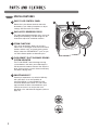
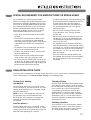
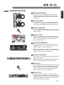
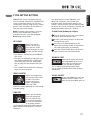
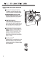
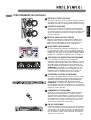
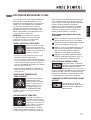
SPECIAL FEATURES
A
EASY-TO-USE CONTROL PANEL
Rotate the cycle selector knob to select the
desired dry cycle. Add cycle options or adjust
settings with the touch of a button.
B
EASY-ACCESS REVERSIBLE DOOR
The wide-opening door provides easy access for
loading and unloading. The door hinge can be
reversed to adjust for installation location.
C
STEAM FUNCTIONS
LG’s steam technology allows you to inject
fabrics with a swirling jet of hot steam to refresh
clothes, reduce static, and make ironing easier.
Simply select the STEAMFRESH
™
cycle, or you
can add a Steam option to selected cycles.
D
FLOW SENSE™ DUCT BLOCKAGE SENSING
SYSTEM INDICATOR
The FLOW SENSE™ duct blockage sensing
system detects and alerts you to blockages in
the ductwork that reduce exhaust flow from the
dryer. Clean exhaust systems increase efficiency
and reduce drying times.
E
SMARTDIAGNOSIS™
Should you experience any technical difficulty
with your dryer, it has the capability of
transmitting data via your telephone to the
Customer Information Center. The call center
agent records the data transmitted from your
machine and uses it to analyze the issue,
providing a fast and effective diagnosis (refer to
page 41).
C
E
R
T
I
F
I
E
D
D
E
S
I
G
N
C
AE
B
D
8

ENGLISH
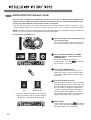
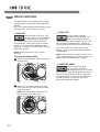
B
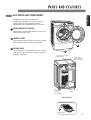
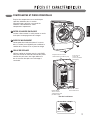
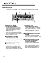
LEVELING FEET
Four leveling feet (two in the front, and two in the back)
adjust to improve dryer stability on uneven floors.
A
FRONT-MOUNT LINT FILTER
Front-mount lint filter allows for easy access and
cleaning after every load.
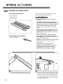
KEY PARTS AND COMPONENTS
In addition to the special features and
components outlined in the Special Features
section, there are several other important
components that are referenced in this manual.
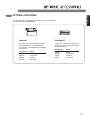
DRYING RACK
Use the drying rack with the RACK DRY cycle to safely dry
such items as sweaters, delicates and gym shoes without
tumbling or overheating.
C
Included Accessories
Drying Rack
C
B
A
Rear of Dryer
Terminal Block
Access Panel
(Electric Models)
Power Cord Location
(Gas Models)
Gas
Connection
Location
(Gas Models)
Exhaust Duct
Outlet
9

24 in.
2*
(155 cm
2
)
18" min.*
(45.7 cm)
1"*
(2.5 cm)
30"
(76.1cm)
30"
(76.1cm)
5"**
(12.7 cm)
48 in.
2*
(310 cm
2
)
14" max.*
(35.6 cm)
3"
*
(7.6 cm)
3"
*
(7.6 cm)
1"
(2.5 cm)
27"
(68.6 cm)
1"
(2.5 cm)
1"*
(2.5 cm)
5"**
(12.7 cm)
14" max.*
(35.6 cm)
18" min.*
(45.7 cm)
0"
(0 cm)
39"
(98.3 cm)
1"
(2.5 cm)
27"
(68.6 cm)
1"
(2.5 cm)
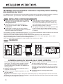
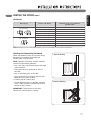
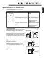
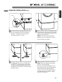
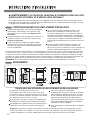
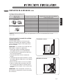
CLEARANCES
WARNING: Read all installation instructions completely before installing
and operating your dryer!
It is important that you review this entire manual before installing and using your dryer. Detailed instructions concerning
electrical connections, gas connections, and exhaust requirements are provided on the following pages.
Do not operate your dryer at temperatures below 45 ºF (7 ºC). At lower temperatures, the dryer might not shut off at the
end of an automatic cycle. This can result in longer drying times.
The dryer must not be installed or stored in an area where it will be exposed to water and/or weather.
Check code requirements. Some codes limit, or do not permit, installation of the dryer in garages, closets, mobile
homes or sleeping quarters. Contact your local building inspector.
NOTE: No other fuel-burning appliance can be installed in the same closet as a dryer.
INSTALLATION LOCATION REQUIREMENTS
A location that allows for proper exhaust installation.
A gas dryer must be exhausted to the outdoors. See
Venting Requirements.
A grounded electrical outlet located within 2 ft.
(61 cm) of either side of the dryer. See Electrical
Requirements.
A sturdy floor to support the total dryer weight of
200 lbs (90.7 kg). The combined weight of a companion
appliance should also be considered.
A level floor with a maximum slope of 1 inch (2.5 cm)
under entire dryer. If slope is greater than 1 inch (2.5
cm), install the Extended Dryer Feet Kit. Clothes may
not tumble properly, and automatic sensor cycles may
not operate correctly if dryer is not level.
For a garage installation, you will need to place the dryer
at least 18 inches (46 cm) above the floor. If using a
pedestal, you will need 18 inches (46 cm) to the bottom
of the dryer.
w
The following spacing dimensions are recommended
for this dryer. This dryer has been tested for spacing
of 0 inches (0 cm) clearance on the sides and rear.
Recommended spacing should be considered for the
following reasons:
Additional spacing should be considered for ease of
installation and servicing.
Additional clearances might be required for wall, door
and floor moldings.
Additional spacing should be considered on all sides of
the dryer to reduce noise transfer.
For closet installation, with a door, minimum ventilation
openings in the top and bottom of the door are required.
Louvered doors with equivalent ventilation openings are
acceptable.
Companion appliance spacing should also be
considered.
Suggestion: There should be at least a little space around the dryer (or any other appliance) to eliminate the transfer
of vibration from one to the other. Too much vibration, it could cause them to make noise or touch each other causing
paint damage and making even more noise.
Installation spacing for recessed area or closet installation
10

ENGLISH
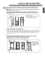
30"
(76.1cm)
5"**
(12.7 cm)
1"**
(2.5 cm)
1"
(2.5 cm)
1"
(2.5 cm)
27"
(68.6 cm)
9"**
(22.9 cm)
7"* (17.8 cm)
7"* (17.8 cm)
1"* (2.5 cm)
5
"**
(14 cm)
1/2
77
1/2
"
(196.8 cm)
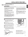
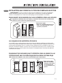
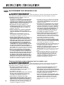
For cabinet installation with a door, minimum ventilation openings in the top of the cabinet
are required.
Recommended installation spacing for cabinet installation
INSTALLATION WITH OPTIONAL PEDESTAL BASE OR STACKING KIT
WARNING : If you are installing your dryer using an optional pedestal base or stacking kit, please
refer to Optional Accessories in this manual or to the instructions for your pedestal or stacking kit
before proceeding with the installation.
*Required spacing
** For side or bottom venting, 2 inches
(5.1 cm) spacing is allowed.
The dimensions shown are for the recommended spacing.
Recommended installation spacing for recessed or closet
installation, with stacked washer and dryer
Closet ventilation requirements
Closets with doors must have both an upper and lower vent to prevent heat and moisture buildup in
the closet. One upper vent opening with a minimum opening of 48 sq. in. (310 cm
2
) must be installed
no lower than 6 feet above the floor. One lower vent opening with a minimum opening of 24 sq. in.
(155 cm
2
) must be installed no more than one foot above the floor. One example shown uses vent
grilles in the door.
*Required spacing
** For side or bottom
venting, 2 inches
(5.1 cm) spacing is
allowed.
11

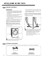
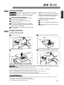
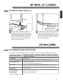
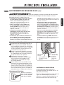
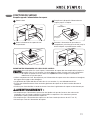
Position the dryer in the final location. Place
a level across the top of the dryer.
1
Level
Leveling Feet
Use an adjustable wrench to turn the leveling
feet. Turn clockwise to raise the dryer or
counterclockwise to lower it. Raise or lower
the leveling feet until dryer is level from
side to side and front to back.
Make sure that all 4 leveling feet are in firm
contact with the floor.
2
•Allfourleveling feetmustrestsolidly on the
floor. Gently push on the top corners of the
dryer to make sure that the dryer does not
rock from corner to corner.
If you are installing the dryer on the optional
pedestal, you must use the leveling feet on the
pedestal to level the dryer. The dryer leveling feet
should be fully retracted.
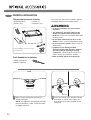
OPTIONAL ACCESSORIES
For these and other LG products, contact your local LG dealer, or visit our Web site at www.lg.com.
Stacking Kit
(sold separately)
Pedestal
(sold separately)
LEVELING THE DRYER
To ensure that the dryer provides optimal drying
performance, it must be level. To minimize
vibration, noise, and unwanted movement, the
floor must be a perfectly level, solid surface.
NOTE: Adjust the leveling feet only as far as
necessary to level the dryer. Extending the
leveling feet more than necessary can cause
the dryer to vibrate.
WARNING
•Toreducetheriskofinjurytopersons,adhere
to all industry recommended safety procedures
including the use of long sleeved gloves and
safety glasses.
•Theappliancesareheavy.Twoormorepeople
are required when installing the dryer.
•Failuretofollowallofthesafetywarningsinthis
manual could result in property damage, injury
to persons or death.
w
12

ENGLISH
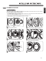
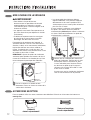
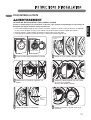
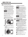
TO REMOVE THE DOOR
wWARNING
THEDRYERDOORISVERYLARGEANDHEAVY.Failure to follow the instructions below can result in damage
to the dryer, property damage or injury to persons .
• Toavoiddamagetothedryerorthedoor,supportthedoorwithastoolorboxthatfitsunderthedoor,orhave
an assistant support the weight of the door.
• AlwaysreversethedoorBEFOREstackingthedryerontopofthewasher.
• Avoiddroppingthedoortoavoiddamagetothedoororthefloor.
Remove four dummy screws by driver.
3
Hinge
Dummy
Screw
Remove door from cabinet cover.
6
Remove
Door
Check screws to remove (Left 6, Right 4).
2
Hold on the hinge while remove 4 screws of
hinge (to prevent door dropping).
5
Hinge Screw
Open the door to reverse.
1
Open Door
Remove two screws and disassembly Latch.
4
Latch Screw
13

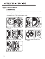
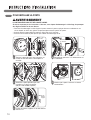
TO INSTALL THE DOOR
wWARNING
THEDRYERDOORISVERYLARGEANDHEAVY.Failure to follow the instructions below can result in damage
to the dryer, property damage or injury to persons .
• Toavoiddamagetothedryerorthedoor,supportthedoorwithastoolorboxthatfitsunderthedoor,orhave
an assistant support the weight of the door.
• AlwaysreversethedoorBEFOREstackingthedryerontopofthewasher.
• Avoiddroppingthedoortoavoiddamagetothedoororthefloor.
Insert latch to right side and install screws.
3
Latch
Screw
Move door to left side and insert a hinge to
hinge hole.
1
Hinge hole
Screw down four dummy screws right side.
4
Hinge
Dummy
Screw
Check that the door closes and latches
properly.
5
Swing Door
Hold on hinge while screw down a hinge
(to prevent door dropping).
2
Hinge Screw
14

ENGLISH
15
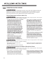
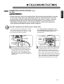
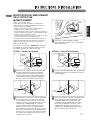
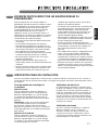
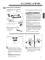
CHANGING THE DRYER VENT LOCATION
Your new dryer is shipped to vent to the rear.
It can also be configured to vent to the bottom or side
(right-side venting is not available on gas models).
An adapter kit, part number 383EEL9001B, may be
purchased from your LG retailer. This kit contains the
necessary duct components to change the dryer vent
location.
Remove the rear exhaust duct retaining
screw. Pull out the exhaust duct.
1
1
Rear
Exhaust Duct
Retaining
Screw
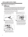
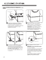
Preassemble a 4 inches (10.2 cm) elbow to the
next 4-inches (10.2 cm) duct section, and secure
all joints with duct tape. Be sure that the male
end of the elbow faces AWAY from the dryer.
Insert the elbow/duct assembly through the side
opening and press it onto the adapter duct.
Secure in place with duct tape.
Be sure that the male end of the duct protrudes
1½ inches (3.8 cm) to connect the remaining
ductwork.
Attach cover plate to the back of the dryer with
included screw.
1
1
/2"
(3.8 cm)
3
Elbow
Cover
Plate
Insert the
4 inches
(10.2 cm) elbow through
the rear opening and press it onto the
adapter duct. Be sure that the male end of
the elbow faces down through hole in the
bottom of the dryer. Secure in place with
duct tape.
Attach the cover plate to the back of the
dryer with included screw.
3
Elbow
Cover
Plate
Press the tabs on the knockout and carefully
remove the knockout for the desired vent
opening (right-side venting is not available on
gas models). Press the adapter duct onto the
blower housing and secure to the base of the
dryer as shown.
2
Knockout
Bracket
Adapter
Duct
OPTION 1: Side Venting
Press the adapter duct onto the blower
housing and secure to the base of the dryer
as shown.
2
Bracket
Adapter
Duct
OPTION 2: Bottom Venting
WARNING
w
•Useaheavymetalvent.
•Donotuseplasticorthinfoilduct.
•Cleanoldductsbeforeinstallingthisdryer.
•Toreducetheriskofinjurytopersons,adheretoall
industry recommended safety procedures including
the use of long sleeved gloves and safety glasses.
•Failuretofollowallofthesafetywarningsinthis
manual could result in property damage, injury to
persons or death.

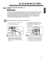
VENTING THE DRYER
•Do not crush or collapse ductwork. Failure
to follow these instructions can result in fire
or death.
•Do not allow ductwork to rest on or
contact sharp objects. Failure to follow these
instructions can result in fire or death.
•If connecting to existing ductwork, make
sure it is suitable and clean before installing
the dryer. Failure to follow these instructions
can result in fire or death.
•Venting must conform to local building
codes. Failure to follow these instructions can
result in fire or death.
•GasdryersMUSTexhausttotheoutdoors.
Failure to follow these instructions can result
in fire or death.
•Use only 4-inch (10.2 cm) rigid or flexible
metal ductwork inside the dryer cabinet and
for venting outside. Failure to follow these
instructions can result in fire or death.
•To reduce the risk of fire, combustion, or
accumulation of combustible gases, DO
NOT exhaust dryer air into an enclosed and
unventilated area, such as an attic, wall,
ceiling, crawl space, chimney, gas vent, or
concealed space of a building. Failure to
follow these instructions can result in fire
or death.
•To reduce the risk of fire, DO NOT exhaust
the dryer with plastic or thin foil ducting.
Failure to follow these instructions can result
in fire or death.
•The exhaust duct must be 4 inches
(10.2 cm) in diameter with no obstructions.
The exhaust duct should be kept as short as
possible. Make sure to clean any old ducts
before installing your new dryer. Failure to
follow these instructions can result in fire or
death.
•Rigid or semirigid metal ducting is
recommended for use between the dryer
and the wall. In special installations when
it is impossible to make a connection with
the above recommendations, a UL-listed
flexible metal transition duct may be used
between the dryer and wall connection only.
The use of this ducting will affect drying
time. Failure to follow these instructions can
result in fire or death.
•DO NOT use sheet metal screws or other
fasteners which extend into the duct that
could catch lint and reduce the efficiency
oftheexhaustsystem.Securealljoints
with duct tape. Failure to follow these
instructions can result in fire or death.
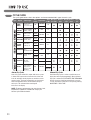
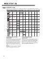
•To maximize operating results, please
observe the duct length limitations noted in
the chart on page 17. Failure to follow these
instructions can result in fire or death.
•Ductwork is not provided with the dryer.
You should obtain the necessary ductwork
locally. The end cap should have hinged
dampers to prevent backdraft when the
dryer is not in use. Failure to follow these
instructions can result in fire or death.
•The Total length of flexible metal duct shall
not exceed 8 ft. (2.4m)
•In Canada, that only those foil-type flexible
ducts, if any, specifically identified for use
with the appliance by the manufacturer
shall be used. In the United States, that only
those foil-type flexible ducts, if any, specifically
identified for use with the appliance by the
manufacturer and that comply with the Outline
for Clothes Dryer Transition Duct, Subject
2158A, shall be used.
wWARNING: To reduce the risk of fire, electric shock, or injury to persons when using this
appliance, follow basic precautions, including the following:
16

ENGLISH
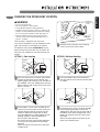
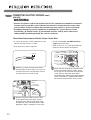
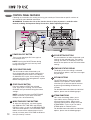
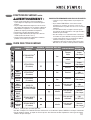
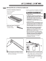
Routing and Connecting Ductwork
Follow the guidelines below to maximize drying
performance and reduce lint buildup and
condensation in the ductwork.
NOTE: Ductwork and fittings are NOT included
and must be purchased separately.
•Use4-inch(10.2cm)diameterrigidorsemirigid
metal ductwork.
•Theexhaustductrunshouldbeasshortas
possible.
•Useasfewelbowjointsaspossible.
•Themaleendofeachsectionofexhaustduct
must point away from the dryer.
•Useducttapeonallductjoints.
•Insulateductworkthatrunsthroughunheated
areas in order to reduce condensation and lint
buildup on duct surfaces.
IMPORTANT: Failure to exhaust the dryer
correctly will void the dryer’s warranty.
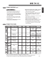
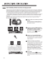
VENTING THE DRYER (cont.)
Correct Venting
Incorrect Venting
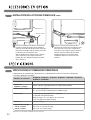
NOTE: Deduct 6 ft. (1.8 m) for each additional elbow. It is not recommended to use more than four 90° elbows.
65 ft. (19.8 m)
55 ft. (16.8 m)
47 ft. (13.7 m)
36 ft. (11.0 m)
28 ft. (8.5 m)
55 ft. (16.8 m)
47 ft. (13.7 m)
41 ft. (12.5 m)
30 ft. (9.1 m)
22 ft. (6.7 m)
Ductwork
4"
(10.2 cm)
4"
(10.2 cm)
Recommended
2
1
/2"
(6.35 cm)
Use Only for Short
Run Installations
Wall Cap Type
0
1
2
3
4
0
1
2
3
4
Number of 90° Elbows
Maximum Length of 4-inch Diameter
Rigid Metal Duct
17

18
Electrical Requirements for Gas Models Only
• Do not, under any circumstances, cut or
remove the third (ground) prong from the power
cord. Failure to follow this warning can result in
fire, explosion, or death.
• For personal safety, this dryer must be properly
grounded. Failure to follow this warning can result
in fire, explosion, or death.
• The power cord of this dryer is equipped with
a 3-prong (grounding) plug which mates with
a standard 3-prong (grounding) wall outlet
to minimize the possibility of electric shock
hazard from this appliance. Failure to follow this
warning can result in fire, explosion, or death.
• This dryer must be plugged into a
60 Hz, 120 VAC. grounded outlet protected by
a 15-ampere fuse or circuit breaker. Failure to
follow this warning can result in fire, explosion,
or death.
• Where a standard 2-prong wall outlet is
encountered, it is your personal responsibility
and obligation to have it replaced with a
properly grounded 3-prong wall outlet. Failure
to follow this warning can result in fire, explosion,
or death.
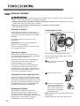
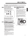
CONNECTING GAS DRYERS
•Gas supply requirements:
As shipped from the factory, this dryer is
configured for use with natural gas. It can be
converted for use with LP (Liquefied Propane)
gas. Gas pressure must not exceed 13 inches
of water column.
•A qualified service or gas company technician
must connect the dryer to the gas service.
Failure to do so can result in fire, explosion,
or death.
•Isolate the dryer from the gas supply system
by closing its individual manual shutoff valve
during any pressure testing of the gas supply.
Failure to do so can result in fire, explosion,
or death.
•Supplylinerequirements:
Your laundry room must have a rigid gas
supplylinetoyourdryer.IntheUnitedStates,
anindividualmanualshutoffvalveMUSTbe
installed within at least 6 ft. (1.8 m) of the dryer,
in accordance with the National Fuel Gas Code
ANSIZ223.1orCanadiangasinstallationcode
CSAB149.1.A
1
⁄8 - inch NPT pipe plug must
be installed. Failure to do so can result in fire,
explosion, or death
•If using a rigid pipe, the rigid pipe should be
½-inchIPS.Ifacceptableunderlocalcodes
and ordinances and when acceptable to your
gas supplier,
3
⁄8 - inch approved tubing may be
used where lengths are less than 20 ft.
(6.1 m). Larger tubing should be used for
lengths in excess of 20 ft. (6.1 m). Failure to do
so can result in fire, explosion, or death.
•Connect the dryer to the type of gas shown on
the nameplate. Failure to do so can result in fire,
explosion, or death.
•To prevent contamination of the gas valve,
purge the gas supply of air and sediment
before connecting the gas supply to the dryer.
Before tightening the connection between the
gas supply and the dryer, purge remaining air
until the odor of gas is detected. Failure to do
so can result in fire, explosion, or death.
•DO NOT use an open flame to inspect for gas
leaks. Use a noncorrosive leak-detection fluid.
Failure to do so can result in fire, explosion, or
death.
•UseonlyanewAGA-orCSA-certiedgas
supply line with flexible stainless steel
connectors. Failure to do so can result in fire,
explosion, or death.
•Securelytightenallgasconnections. Failure
to do so can result in fire, explosion, or death.
•Use a pipe-joint compound that is insoluble
in Liquefied Petroleum (LP) gas on all pipe
threads. Failure to do so can result in fire,
explosion, or death.
•DO NOT attempt any disassembly of the dryer;
any disassembly requires the attention and
tools of an authorized and qualified service
person or company. Failure to do so can result
in fire, explosion, or death.
wWARNING: To reduce the risk of fire, electric shock, or injury to persons when using this
appliance, follow basic precautions, including the following:
wWARNING: To reduce the risk of fire, electric shock, or injury to persons when using this
appliance, follow basic precautions, including the following:

ENGLISH
•Installation and service must be performed
by a qualified installer, service agency, or the
gas supplier. Failure to do so can result in fire,
explosion, or death.
•Use only a new stainless steel flexible
connector and a new AGA-certified
connector. Failure to do so can result in fire,
explosion, or death.
•A gas shutoff valve must be installed within
6 ft. (1.8 m) of the dryer. Failure to do so can
result in fire, explosion, or death.
•The dryer is configured for Natural Gas when
shipped from the factory. Make sure that the
dryer is equipped with the correct burner
orifice for the type of gas being used (Natural
Gas or Liquefied Petroleum). Failure to do so
can result in fire, explosion, or death.
•If necessary, the correct orifice (for the LP
orifice kit order part number 383EEL3002D)
should be installed by a qualified technician
and the change should be noted on the dryer.
Failure to do so can result in fire, explosion,
or death.
•All connections must be in accordance with
local codes and regulations. Failure to do so
can result in fire, explosion, or death.
•GasdryersMUSTexhausttotheoutdoors.
Failure to do so can result in fire, explosion,
or death.
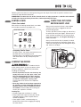
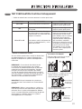
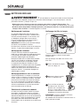
3/8” NPT Gas
Connection
Gas Supply
Shutoff Valve
Connecting the Gas Supply
Make sure that the gas supply to the laundry
room is turned OFF. Confirm that the type
of gas available in your laundry room is
appropriate for the dryer. The dryer is
prepared for Natural Gas with a
3
⁄8 - inch NPT
gas connection.
Remove the shipping cap from the gas
connection at the back of the dryer. Be
careful not to damage the threads of the gas
connector when removing the shipping cap.
Connect the dryer to your laundry room’s gas
supply using a new flexible stainless steel
connector with a
3
⁄8 - inch NPT fitting.
Securely tighten all connections between the
dryer and your laundry room’s gas supply.
Turn on your laundry room’s gas supply and
check all pipe connections (both internal and
external) for gas leaks with a noncorrosive
leak-detection fluid.
1
2
3
4
High-Altitude Installations
The BTU rating of this dryer is AGA-certified for
elevations below 10,000 feet.
If your gas dryer is being installed at an elevation
above 10,000 feet, it must be derated by a
qualified technician or gas supplier.
Electrical Connection
Plug dryer into a
120 VAC, 60 Hz
grounded 3-prong
outlet.
CONNECTING GAS DRYERS (cont.)
1/8” NPT Pipe
Plug
AGA/CSA-Certified
Stainless Steel
Flexible Connector
wWARNING: To reduce the risk of fire, electric shock, or injury to persons when using this
appliance, follow basic precautions, including the following:
19

20
Electrical Requirements for Electric Models Only
•This dryer must be connected to a grounded
metal, permanent wiring system, or an
equipment-grounding conductor must
be run with the circuit conductors and
connected to the equipment-grounding
terminal or lead on the dryer. Failure to do
so can result in fire, explosion, or death.
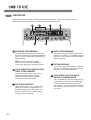
•The dryer has its own terminal block that
must be connected to a separate 240 VAC,
60-Hertz, single-phase circuit, fused at 30
amperes (the circuit must be fused on both
sidesoftheline).ELECTRICALSERVICE
FORTHEDRYERSHOULDBEOFTHE
MAXIMUMRATEVOLTAGELISTEDONTHE
NAMEPLATE. DO NOT CONNECT DRYER
TO 110-, 115-, OR 120-VOLT CIRCUIT. Failure
to follow these instructions can result in fire,
explosion, or death.
•If branch circuit to dryer is 15 ft. (4.5 m)
or less in length, use UL (Underwriters
Laboratories) listed No.-10 AWG wire
(copper wire only), or as required by local
codes. If over 15 ft. (4.50 m), use UL-listed
No.-8 AWG wire (copper wire only), or as
required by local codes. Allow sufficient
slack in wiring so dryer can be moved from
its normal location when necessary. Failure
to do so can result in fire, explosion, or death.
•The power cord (pigtail) connection between
wallreceptacleanddryerterminalblockIS
NOT supplied with dryer. The pigtail must be
the correct plug and wire gauge and must
conform to local codes and with instructions
on the following pages. Failure to follow these
instructions can result in fire, explosion, or
death.
•A 4-wire connection is required for all mobile
and manufactured home installations, as
well as all new construction after January
1, 1996. A 4-wire connection must be used
where local codes do not permit grounding
through the neutral wire. Failure to do so can
result in fire, explosion, or death.
Special Electrical Requirements for Mobile or Manufactured Homes
•Any installation in a manufactured or mobile
home must comply with the Manufactured
Home Construction and Safety Standards
Title 24 CFR, Part 32-80 or Standard CAN/
CSA0Z240 MH and local codes and ordinances.
•A 4-wire connection is required for all mobile
and manufactured home installations, as well
as all new construction after January 1, 1996.
Failure to do so can result in fire, explosion,
or death.
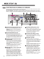
CONNECTING ELECTRIC DRYERS
wWARNING: To reduce the risk of fire, electric shock, or injury to persons when using this
appliance, follow basic precautions, including the following:
wWARNING: To help prevent fire, electric shock, serious injury, or death, the wiring and
grounding must conform to the latest edition of the National Electrical Code, ANSI/NFPA 70 and all
applicable local regulations. Please contact a qualified electrician to check your home’s wiring and
fuses to ensure that your home has adequate electrical power to operate the dryer.
wWARNING: To reduce the risk of fire, electric shock, or injury to persons when using this
appliance, follow basic precautions, including the following:
wWARNING:
To reduce the risk of fire, electric shock, or injury to persons when using this
appliance, follow basic precautions, including the following:
•Donotmodifytheplugandinternalwire
provided with the dryer.
•Thedryershouldbeconnectedto4-holeoutlet.
•Ifitdoesnotttheoutlet,aproperoutletwill
need to be installed by a qualified electrician.
Page is loading ...
Page is loading ...
Page is loading ...
Page is loading ...
Page is loading ...
Page is loading ...
Page is loading ...
Page is loading ...
Page is loading ...
Page is loading ...
Page is loading ...
Page is loading ...
Page is loading ...
Page is loading ...
Page is loading ...
Page is loading ...
Page is loading ...
Page is loading ...
Page is loading ...
Page is loading ...
Page is loading ...
Page is loading ...
Page is loading ...
Page is loading ...
Page is loading ...
Page is loading ...
Page is loading ...
Page is loading ...
Page is loading ...
Page is loading ...
Page is loading ...
Page is loading ...
Page is loading ...
Page is loading ...
Page is loading ...
Page is loading ...
Page is loading ...
Page is loading ...
Page is loading ...
Page is loading ...
Page is loading ...
Page is loading ...
Page is loading ...
Page is loading ...
Page is loading ...
Page is loading ...
Page is loading ...
Page is loading ...
Page is loading ...
Page is loading ...
Page is loading ...
Page is loading ...
Page is loading ...
Page is loading ...
Page is loading ...
Page is loading ...
Page is loading ...
Page is loading ...
Page is loading ...
Page is loading ...
Page is loading ...
Page is loading ...
Page is loading ...
Page is loading ...
Page is loading ...
Page is loading ...
Page is loading ...
Page is loading ...
Page is loading ...
Page is loading ...
Page is loading ...
Page is loading ...
Page is loading ...
Page is loading ...
Page is loading ...
Page is loading ...
Page is loading ...
Page is loading ...
Page is loading ...
Page is loading ...
-
 1
1
-
 2
2
-
 3
3
-
 4
4
-
 5
5
-
 6
6
-
 7
7
-
 8
8
-
 9
9
-
 10
10
-
 11
11
-
 12
12
-
 13
13
-
 14
14
-
 15
15
-
 16
16
-
 17
17
-
 18
18
-
 19
19
-
 20
20
-
 21
21
-
 22
22
-
 23
23
-
 24
24
-
 25
25
-
 26
26
-
 27
27
-
 28
28
-
 29
29
-
 30
30
-
 31
31
-
 32
32
-
 33
33
-
 34
34
-
 35
35
-
 36
36
-
 37
37
-
 38
38
-
 39
39
-
 40
40
-
 41
41
-
 42
42
-
 43
43
-
 44
44
-
 45
45
-
 46
46
-
 47
47
-
 48
48
-
 49
49
-
 50
50
-
 51
51
-
 52
52
-
 53
53
-
 54
54
-
 55
55
-
 56
56
-
 57
57
-
 58
58
-
 59
59
-
 60
60
-
 61
61
-
 62
62
-
 63
63
-
 64
64
-
 65
65
-
 66
66
-
 67
67
-
 68
68
-
 69
69
-
 70
70
-
 71
71
-
 72
72
-
 73
73
-
 74
74
-
 75
75
-
 76
76
-
 77
77
-
 78
78
-
 79
79
-
 80
80
-
 81
81
-
 82
82
-
 83
83
-
 84
84
-
 85
85
-
 86
86
-
 87
87
-
 88
88
-
 89
89
-
 90
90
-
 91
91
-
 92
92
-
 93
93
-
 94
94
-
 95
95
-
 96
96
-
 97
97
-
 98
98
-
 99
99
-
 100
100


LG DLEX2550V Owner's manual
- Category
- Electric laundry dryers
- Type
- Owner's manual
Ask a question and I''ll find the answer in the document
Finding information in a document is now easier with AI
in other languages
- français: LG DLEX2550V Le manuel du propriétaire
Related papers
Other documents
-
LG Electronics DLGX4371K Installation guide
-
-
 Kenmore Elite 91983 Owner's manual
-
Kenmore 796.8099 Use & Care Manual And Installation Instructions
-
-
-
-
LG SIGNATURE DLEX9500K Owner's manual
-
-
