KitchenAid KUIX335HBL Installation guide

Category
Barbecues & grills
Type
Installation guide

This manual is also suitable for

ICE MAKER INSTALLATION INSTRUCTIONS
INSTRUCTIONS D’INSTALLATION DE LA MACHINE À GLAÇONS
INSTRUCCIONES DE INSTALACIÓN DE LA FÁBRICA DE HIELO
W11246206A
ICE MAKER SAFETY
You can be killed or seriously injured if you don't immediately
You
can be killed or seriously injured if you don't
follow
All safety messages will tell you what the potential hazard is, tell you how to reduce the chance of injury, and tell you what can
happen if the instructions are not followed.
Your safety and the safety of others are very important.
We have provided many important safety messages in this manual and on your appliance. Always read and obey all safety
messages.
This is the safety alert symbol.
This symbol alerts you to potential hazards that can kill or hurt you and others.
All safety messages will follow the safety alert symbol and either the word “DANGER” or “WARNING.”
These words mean:
follow instructions.
instructions.
DANGER
WARNING
TABLE OF CONTENTS / TABLE DES MATIÈRES / ÍNDICE
ICE MAKER SAFETY ..................................1
INSTALLATION INSTRUCTIONS ...............2
Unpack the Ice Maker ..............................2
Location Requirements ............................2
Electrical Requirements ...........................3
Water Supply Requirements ....................3
Vacation or Extended Time Without Use ..3
Connect Water Supply .............................4
Drain Pump Installation
(on some models) .....................................5
Drain Connection .....................................7
Door Panel and Hinge Removal ...............9
Custom Wood Panel Use .......................13
Auxiliary Grill Installation ........................16
Leveling ..................................................16
Deep Clean .............................................17
SÉCURITÉ DE LA MACHINE
À GLAÇONS ..............................................19
INSTRUCTIONS D’INSTALLATION .........20
Déballage de la machine à glaçons .......20
Exigences d’emplacement .....................20
Spécications électriques ......................21
Spécications de l’alimentation en eau ..21
Vacances ou longue période
d’inutilisation ..........................................21
Raccordement à la canalisation d’eau ..22
Installation de la pompe de vidange
(sur certains modèles) ............................23
Raccord au drain ....................................26
Démontage du panneau de porte
etdes charnières ....................................27
Utilisation du panneau en bois
personnalisé ...........................................31
Installation de la grille auxiliaire ..............34
Ajustement de l’aplomb .........................35
Nettoyage en profondeur .......................35
SEGURIDAD DE LA FÁBRICA
DE HIELO ..................................................37
INSTRUCCIONES DE INSTALACIÓN .....38
Cómo desempacar la fábrica de hielo ...38
Requisitos de ubicación .........................38
Requisitos eléctricos ..............................39
Requisitos de suministro de agua .........39
Vacaciones o tiempo prolongado
sinuso ....................................................39
Conexión del suministro de agua ..........40
Instalación de la bomba de desagüe
(en algunos modelos) .............................41
Conexión de desagüe ............................44
Cómo quitar los paneles de
las puertas y las bisagras .......................45
Uso del panel de madera
personalizado .........................................49
Instalación de la rejilla auxiliar ................52
Nivelación ...............................................53
Limpieza intensa ....................................53
2
INSTALLATION INSTRUCTIONS
Unpack the Ice Maker
Removing Packaging Materials
Remove tape and glue from your ice maker before using.
To remove any remaining tape or glue from the exterior of the
ice maker, rub the area briskly with your thumb. Tape or glue
residue can also be easily removed by rubbing a small
amount of liquid dish soap over the adhesive with your
ngers. Wipe with warm water and dry.
Do not use sharp instruments, rubbing alcohol, ammable
uids, or abrasive cleaners to remove tape or glue. Do not
use chlorine bleach on the stainless steel surfaces of the ice
maker. These products can damage the surface of your ice
maker.
Cleaning Before Use
After you remove all of the packaging materials, clean the inside
of your ice maker before using it. See the cleaning instructions in
the “Ice Maker Care” section.
Location Requirements
To ensure proper ventilation for your ice maker, the front
side must be completely unobstructed. The ice maker may
be closed-in on the top and three sides, but the installation
should allow the ice maker to be pulled forward for servicing if
necessary.
The auxiliary grill kit provided (only on custom panel models)
can be used to align the toe grill with the rest of the cabinets
while not obstructing ventilation of the ice maker.
Installation of the ice maker requires a cold water supply inlet
of 1/4" (6.35 mm) OD soft copper tubing with a shutoff valve
or a Whirlpool supply line Part Number 8212547RB, and a
Whirlpool approved drain pump, Part Number 1901A, only to
carry the water to an existing drain.
Choose a well-ventilated area with temperatures above 55°F
(13°C) and below 110°F (43°C). Best results are obtained
between 70°F and 90°F (21ºC and 32°C).
The ice maker must be installed in an area sheltered from the
elements, such as wind, rain, water spray, or drip.
When installing the ice maker under a counter, follow the
recommended opening dimensions shown. Place electrical
and plumbing xtures in the recommended location as shown.
NOTES:
Check that the power supply cord is not damaged or
pinched or kinked between the ice maker and the cabinet.
Check that the water supply line is not damaged or
pinched or kinked between the ice maker and the cabinet.
Check that the drain line (on some models) is not
damaged or pinched or kinked between the ice maker and
the cabinet.
IMPORTANT SAFETY INSTRUCTIONS
WARNING
:
To reduce the risk of fire, electric shock, or injury when using your ice maker, follow these basic
precautions
:
SAVE THESE INSTRUCTIONS
Plug into a grounded 3 prong outlet.
Do not remove ground prong.
Do not use an adapter.
Do not use an extension cord.
Disconnect power before manually cleaning the inside components.
Disconnect power before servicing.
Replace all parts and panels before operating.
Use two or more people to move and install ice maker.
WARNING
Excessive Weight Hazard
Use two or more people to move and install ice maker.
Failure to do so can result in back or other injury.
3
Choose a location where the oor is even. It is important for
the ice maker to be level in order to work properly. If needed,
you can adjust the height of the ice maker by changing the
height of the leveling legs. See “Leveling.”
Electrical Requirements
Before you move your ice maker into its nal location, it is
important to make sure you have the proper electrical connection:
A 115 V, 60 Hz., AC only, 15 or 20 A electrical supply, properly
grounded in accordance with the National Electrical Code and
local codes and ordinances, is required.
It is recommended that a separate circuit, serving only your ice
maker, be provided. Use a receptacle which cannot be turned off
by a switch or pull chain.
IMPORTANT: If this product is connected to a GFCI (Ground
Fault Circuit Interrupter) equipped outlet, nuisance tripping of the
power supply may occur, resulting in loss of cooling. Ice quality
may be affected. If nuisance tripping has occurred, and if the
condition of the ice appears poor, dispose of it.
Recommended Grounding Method
The ice maker must be grounded. The ice maker is equipped with
a power supply cord having a 3 prong grounding plug. The cord
must be plugged into a mating, 3 prong, grounding-type wall
receptacle, grounded in accordance with the National Electrical
Code and local codes and ordinances. If a mating wall receptacle
is not available, it is the personal responsibility of the customer to
have a properly grounded, 3 prong wall receptacle installed by a
qualied electrician.
Water Supply Requirements
Check that the water supply lines are insulated against freezing
conditions. Ice formations in the supply lines can increase water
pressure and damage your ice maker or home. Damage from
frozen supply lines is not covered by the warranty.
A cold water supply with water pressure of between 30 and
120 psi (207 and 827 kPa) is required to operate the ice maker.
If you have questions about your water pressure, call a licensed,
qualied plumber.
Reverse Osmosis Water Supply
IMPORTANT:
A reverse osmosis water ltration system is not recommended
for ice makers that have a drain pump installed.
For gravity drain systems only.
The pressure of the water supply coming out of a reverse
osmosis system going to the water inlet valve of the ice maker
needs to be between 30 and 120 psi (207 and 827 kPa).
If a reverse osmosis water ltration system is connected to your
cold water supply, the water pressure to the reverse osmosis
system needs to be a minimum of 40 to 60 psi (276 to 414 kPa).
NOTE: The reverse osmosis system must provide 1 gal. (3.8 L) of
water per hour to the ice maker for proper ice maker operation. If
a reverse osmosis system is desired, only a whole-house capacity
reverse osmosis system, capable of maintaining the steady
water supply required by the ice maker, is recommended. Faucet
capacity reverse osmosis systems are not able to maintain the
steady water supply required by the ice maker.
If the water pressure to the reverse osmosis system is less than
40 to 60 psi (276 to 414 kPa):
Check to see whether the sediment lter in the reverse
osmosis system is blocked. Replace the lter if necessary.
Allow the storage tank on the reverse osmosis system to rell
after heavy usage.
If you have questions about your water pressure, call a licensed,
qualied plumber.
Vacation or Extended Time Without Use
When you will not be using the ice maker for an extended
period of time, turn off the water and power supply to the ice
maker.
Check that the water supply lines are insulated against
freezing conditions. Ice formations in the supply lines can
increase water pressure and cause damage to your ice
maker or home. Damage from freezing is not covered by the
warranty.
B
A
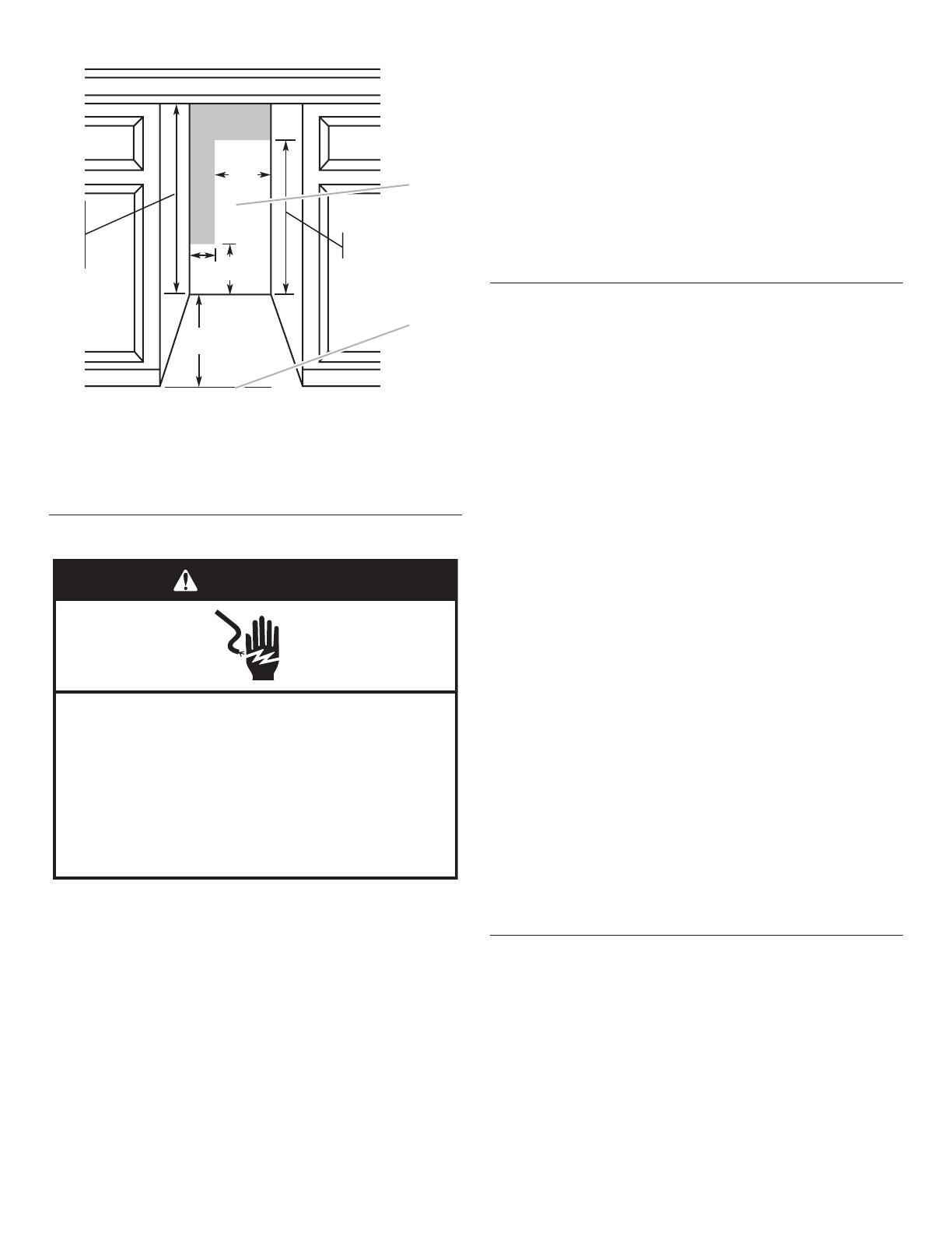
A. Recommended location for electrical and plumbing xtures
B. Floor level
Electrical Shock Hazard
Plug into a grounded 3 prong outlet.
Do not remove ground prong.
Do not use an adapter.
Do not use an extension cord.
Failure to follow these instructions can result in death,
fire, or electrical shock.
WARNING
34"
(86.4 cm)
Min.
34¹⁄
2
"
(87.6 cm)
Max.
24"
(60.96 cm)
28¹⁄
2
"
(72.4 cm)
3¹⁄
2
"
(8.9 cm)
11¹⁄
2
"
(29.2 cm)
9"
(22.9 cm)
4
Connect Water Supply
Read all directions before you begin.
IMPORTANT:
Plumbing shall be installed in accordance with the
International Plumbing Code and any local codes and
ordinances.
Use copper tubing or Whirlpool supply line, Part Number
8212547RP, and check for leaks.
Install tubing only in areas where temperatures will remain
above freezing.
Tools Needed
Gather the required tools and parts before starting installation:
Flat-blade screwdriver
7/16" and 1/2" open-end wrenches or two adjustable
wrenches
1/4" nut driver
NOTE: Do not use a piercing-type or 3/16" (4.76 mm) saddle
valve which reduces water ow and clogs more easily.
Connecting the Water Line
1. Turn off main water supply. Turn on nearest faucet long
enough to clear line of water.
2. Using a 1/2" copper supply line with a quarter-turn shutoff
valve or the equivalent, connect the ice maker as shown.
NOTE: To allow sufcient water ow to the ice maker a
minimum 1/2" diameter home supply line is recommended.
3. Now you are ready to connect the copper tubing. Use 1/4"
(6.35 mm) O.D. soft copper tubing for the cold water supply.
Ensure that you have the proper length needed for the job.
Be sure both ends of the copper tubing are cut square.
Slip compression sleeve and compression nut on copper
tubing as shown. Insert end of tubing into outlet end
squarely as far as it will go. Screw compression nut onto
outlet end with adjustable wrench. Do not overtighten.
4. Place the free end of the tubing into a container or sink, and
turn on main water supply and ush out tubing until water is
clear. Turn off shutoff valve on the water pipe.
IMPORTANT: Always drain the water line before making
the nal connection to the inlet of the water valve to avoid
possible water valve malfunction.
5. Water inlet tube is located on the rear side of the ice maker as
shown in "Rear View" illustration. Bend the copper tubing to
match with water line inlet. Leave the coil of copper tubing as
it is to allow the ice maker to be pulled out of the cabinet or
away from the wall for service.
Rear View
6. Remove and discard the short, plastic tube from the end of
the water line inlet.
7. Thread the nut onto the end of the tubing. Tighten the nut by
hand. Then tighten it with a wrench two more turns. Do not
overtighten.
NOTE: To avoid rattling, be sure the copper tubing does not
touch the cabinet’s side wall or other parts inside the cabinet.
A
B
A. Bulb
B. Nut
B
C
A
A. Compression sleeve
B. Compression nut
C. Copper tubing
A
C
B
A. Copper tubing
B. Water supply tube clamp
C. Inlet water tube clamp and
supply line connector
DAB C
A. Line to ice maker
B. Nut (purchased)
C. Ferrule (purchased)
D. Supplied line from ice maker
5
8. Install the water supply tube clamp around the water supply
line to reduce strain on the coupling.
9. Turn shutoff valve ON.
10. Check for leaks. Tighten any connections (including
connections at the valve) or nuts that leak.
Drain Pump Installation
(on some models)
NOTES:
Connect drain pump to your drain in accordance with all state
and local codes and ordinances.
It may be desirable to insulate drain tube thoroughly up
to drain inlet to minimize condensation on the drain tube.
Insulated tube kit Part Number W10365792 is available for
purchase.
Drain pump is designed to pump water to a maximum height
of 10 ft (3 m). Use only Whirlpool approved drain pump kit
Part Number 1901A.
Do not connect the outlet end of the drain tube to a closed
pipe system to keep drain water from backing up into the ice
maker.
Kit Contains:
Drain pump kit Part Number 1901A
5/8" I.D. x 5
1
/
8
" drain tube (ice maker bin to drain pump
reservoir inlet)
1/2" I.D. x 10 ft (3 m) drain tube hose (drain pump discharge
to household drain)
5/16" I.D. x 32" (81 cm) vent tube (drain pump reservoir vent
to ice maker cabinet back)
Cable tie (secures vent tube to back of ice maker) (1)
#8-32 x 3/8" pump mounting screws (secures drain pump to
baseplate and clamps to back of ice maker) (5)
5/8" small adjustable hose clamp (secures vent to drain
pump)
7/8" large adjustable hose clamp, (secures drain tube to ice
maker bin and drain pump reservoir inlet) (3)
Rear panel (2)
Instruction sheet
If Ice Maker Is Currently Installed
NOTE: If ice maker is not installed, please proceed to “Drain
Pump Installation” section.
1. Push the selector switch to the OFF position.
2. Unplug ice maker or disconnect power.
3. Turn off water supply. Wait 5 to 10 minutes for the ice to fall
into the storage bin. Remove all ice from bin.
4. Unscrew the drain cap from the bottom of the water
pan located inside the storage bin. Allow water to drain
completely. Replace drain cap. See “Drain Cap” illustration.
Drain Cap
5. If ice maker is built into cabinets, pull ice maker out of the
opening.
6. Disconnect water supply line. See “Water Supply Line”
illustration.
Water Supply Line
Drain Pump Installation
NOTE: Do not kink, smash or damage tubes or wires during
installation.
1. Unplug ice maker or disconnect power.
2. Remove rear panel. See “Rear Panel” illustration for 5 screw
locations. Pull rear panel away from the drain tube and
discard.
Rear Panel
WARNING
Electrical Shock Hazard
Disconnect power before servicing.
Replace all parts and panels before operating.
Failure to do so can result in death or electrical shock.
A
A. Drain cap
A
C
B
B
C
D
E
A. 1/4" copper tubing
B. Cable clamp
C. 1/4" compression nut
D. Ferrule (sleeve)
E. Ice maker connection
A
A
A. Screw locations
6
3. Remove the old drain tube and clamp attached to the ice
maker bin.
NOTE: Discard old drain tube and clamp.
4. Install new drain tube (5/8" I.D. x 5¹⁄
8
") from ice maker bin to
drain pump reservoir inlet using new adjustable clamps. See
“Drain Tube” illustration.
NOTES:
Do not kink.
Trim tube length if required.
Drain Tube
5. Install vent tube (5/16" I.D. x 32" [81 cm]) to drain pump
reservoir vent. Use supplied 5/8" small adjustable clamps.
See “Parts Locations” illustration. Use plastic retainer to keep
vent hose secure to top of inner deck.
NOTE: Do not install household drain tube at this time.
Parts Locations
6. Remove power cord clamp and ground screw attached to ice
maker power cord, which is mounted to the unit base. See
“Parts Locations” illustration.
NOTE: Clamp and screw will be reused.
7. Slide drain pump into the ice maker base on the right side.
The pump mounting tab should slip into the rectangular slot
in the ice maker base. It will be necessary to tip the pump
slightly to slip into the slot. See “Drain Pump Mounting Tab
Slot” illustration.
Drain Pump Mounting Tab Slot
Drain Pump Installed
8. Align the 2 screw holes at the rear of the pump. Use two
#8-32 x 3/8" screws, supplied. See “Parts Locations”
illustration.
9. Connect drain tube to ice maker bin outlet (5/8" I.D.), using
7/8" adjustable clamp, supplied. See “Drain Tube” illustration.
10. Coil ice maker power cord into a 4" (10.2 cm) diameter
coil. Wrap electrical tape around the power cord in several
places to keep the cord in a coil. Locate coiled power cord
between the drain pump and side of enclosure and plug into
the receptacle of the drain pump. See “Parts Locations”
illustration.
11. Attach the drain pump power cord to ice maker unit base with
clamp and screw (removed in Step 6) that was used to attach
ice maker power cord. See “Parts Locations” illustration.
12. Place new rear panel (small one for 15" ice makers, large one
for 18") against the back of the ice maker. Route the vent tube
and drain pump discharge tube through cutouts in the rear
panel.
13. Secure rear panel with original screws. See “Rear Panel”
illustration.
A
B
C
D
A. 7/8" adjustable hose clamp
B. Drain tube (ice bin to drain pump)
C. 7/8" adjustable hose clamp
D. Drain pump reservoir inlet
C
H
I
G
F
E
D
B
A
A. Vent tube
B. 5/8" hose clamp
C. Drain pump discharge tube
D. Drain pump
E. Ice maker unit power cord
F. #8-32 x 3/8" pump mounting
screws
G. Drain pump power cord,
clamp and screw
H. Plastic retainer
I. Wiring cover
A
A. Mounting tab slot
A
A. Drain pump installed
7
14. Remove wiring cover. Refer following illustration for location of
the screws.
15. Route vent tube through plastic retainer that is located
underneath top deck in open pump area as shown in
illustration. Using cable tie, tie the vent tube to the black
suction tube which is located behind the wiring cover. Refer
"Vent Tube" illustration.
16. Secure wiring cover back in place.
17. Attach 1/2" I.D. x 10 ft (3 m) drain tube to pump discharge
tube. See “Parts Locations” illustration.
NOTE: Do not connect outlet end of drain tube to a closed
pipe system to keep drain water from backing up into the ice
maker
18. Connect ice maker to water supply and install ice maker as
specied by the product installation instructions
Vent Tube
NOTE: Do not pinch, kink or damage the vent tube. Check that it
is not damaged or pinched or kinked between the cabinet and the
ice maker.
19. Check all connections for leaks.
20. Plug in ice maker or reconnect power.
21. Turn on ice maker.
22. Wait for rinsing cycle, approximately 5 minutes, to be sure the
ice maker is operating properly.
Drain Connection
Gravity Drain System
Connect the ice maker drain to your drain in accordance with all
state and local codes and ordinances. If the ice maker is provided
with a gravity drain system, follow these guidelines when
installing drain lines. This will help keep water from owing back
into the ice maker storage bin and potentially owing onto the
oor, causing water damage.
Drain lines must have a minimum of 5/8" (15.88 mm) I.D.
(inside diameter).
Drain lines must have a 1" drop per 48" (2.54 cm drop per
122 cm) of run or 1/4" drop per 12" (6.35 mm per 30.48 cm) of
run and must not have low points where water can settle.
The oor drains must be large enough to accommodate
drainage from all drains.
The ideal installation has a standpipe with a 1¹⁄
2
" (3.81 cm) to
2" (5.08 cm) PVC drain reducer installed directly below the
outlet of the drain tube as shown. You must maintain a 1"
(2.54 cm) air gap between the drain hose and the standpipe.
Do not connect the outlet end of the drain tube to a closed
pipe system to keep drain water from backing up into the ice
maker.
IMPORTANT: A drain pump is necessary when a oor drain is not
available. A Drain Pump kit, Part Number 1901A, is available for
purchase.
A
B
A. Wiring cover
B. Screws
A. Vent tube
B. Cable ties
C. Plastic retainer
A
B
C
Electrical Shock Hazard
Plug into a grounded 3 prong outlet.
Do not remove ground prong.
Do not use an adapter.
Do not use an extension cord.
Failure to follow these instructions can result in death,
fire, or electrical shock.
WARNING
8
Side View
Drain Pump System (on some models)
IMPORTANT:
Connect the ice maker drain to your drain in accordance with
the International Plumbing Code and any local codes and
ordinances.
The drain pump discharge line must terminate at an open
sited drain.
Maximum rise 10 ft (3.1 m)
Maximum run 100 ft (30.5 m)
NOTES:
If the drain hose becomes twisted and water cannot drain,
your ice maker will not work.
It may be desirable to insulate the drain line thoroughly
up to the drain inlet. An Insulation Sleeve kit, Part Number
W10365792, is available for purchase.
Do not connect the outlet end of the drain tube to a closed
pipe system to keep drain water from backing up into the ice
maker.
Drain pump maximum capability: For every 1 ft (0.31 m) of
rise, subtract 10 ft (3.1 m) of maximum allowable run.
Connecting the Drain
After ensuring that the drain system is adequate, follow these
steps to properly place the ice maker:
1. Plug into a grounded 3 prong outlet.
2. Style 1— For gravity drain system, push the ice maker into
position so that the ice maker drain tube is positioned over
the PVC drain reducer. See “Gravity Drain System.”
Style 2— For drain pump system connect the drain pump
outlet hose to the drain. See “Drain Pump System.”
3. Recheck the ice maker to be sure that it is level. See
“Leveling.”
4. If it is required by your local sanitation code, seal the cabinet
to the oor with an approved caulking compound after all
water and electrical connections have been made.
A
D
C
B
A. Drain hose
B. 1" (2.54 cm) air gap
C. PVC drain reducer
D. Center of drain should be 23" (58.4 cm) from
front of door, with or without the 3/4" (1.91
cm) panel on the door. The drain should also
be centered from left to right (7
5
/
16
" [18.56 cm]
from either side of the ice maker).
Electrical Shock Hazard
Plug into a grounded 3 prong outlet.
Do not remove ground prong.
Do not use an adapter.
Do not use an extension cord.
Failure to follow these instructions can result in death,
fire, or electrical shock.
WARNING
WARNING
Excessive Weight Hazard
Use two or more people to move and install ice maker.
Failure to do so can result in back or other injury.
1
7
/
8
"
(4.8 cm)
2" - 1
1
/
2
"
(5 cm - 3.8 cm)
23"
(58.4 cm)
1" (2.54 cm)
9
Door Panel and Hinge Removal
1. Unplug the ice maker or disconnect power.
2. Remove the hinge cover from the upper and lower hinges.
3. To remove, cut hinge cover at indicated point using diagonal
cutting plier and remove from around hinges.
NOTE: Reinstall the hinge covers if product is removed from
cabinet installation.
4. Remove the plastic screw cover from the inside of the hinges
and set aside.
5. Remove the top and bottom plastic end caps from the door.
6. Unscrew the door hinge screws completely. Remove hinge pin
from top hinge and set aside.
7. Loosen the cabinet Phillips head screws halfway, so that the
hinge can slide off.
WARNING
Electrical Shock Hazard
Disconnect power before servicing.
Replace all parts and panels before operating.
Failure to do so can result in death or electrical shock.
Crush Hazard
Articulated hinges are self closing and many pinch
points exist prior to cabinet installation.
Do not remove hinge covers until product is ready to
be installed.
Failure to follow these instructions can result in crush,
cut, or pinch injuries.
WARNING
10
8. Repeat steps 6 and 7 on the second hinge.
NOTE: Keep track of where each door hinge was originally
located, at the top or bottom of the unit.
Preparing the Bottom Hinges
1. Once both hinges are removed, unscrew the grill cover by
using a TORX T20
screwdriver.
NOTE: The door may fall open. This is normal.
2. Remove the black screw cover from the grill by opening the
grill cover, pushing the screw cap inwards, and sliding it out to
the side. Remove the hinge shim.
3. To attach the black screw cover to the opposite side, rst pull
the grill cover out.
4. Place the black screw cover between the grill and the screws.
Install the hinge shim on the opposite side, making sure the
notches face down and out.
NOTE: Make sure all of the covers's edges are behind the lip
of the grill, or it will not stay in place.
5. Once the cover is secure, push the grill cover back into its
original position, and replace the grill screws.
Reversing the Hinges
1. Place the hinge shim on the opposite side of the ice maker.
NOTE: The hinge shim is notched on the bottom-inner side to
indicate proper placement. Flip the hinge shims as needed to
make sure that the notches are facing in and down.
Black screw cover
Hinge shim
†TORX and T20 are trademarks of Acument Intellectual Properties, LLC.
11
2. Take the original upper hinge, ip it 180 degrees, and place it
in the lower hinge position on the opposite side, resting on the
cabinet hinge screws (i.e. the upper right hinge is now the
lower left hinge).
NOTE: The extensions on the hinges should always face
inside, not outside.
3. Take the original lower hinge, ip it 180 degrees, and place it
in the upper hinge position on the opposite side resting on the
cabinet hinge screws.
4. Both hinges should be resting on the cabinet hinge screws.
Make sure that all screws are fully tightened. Take hinge pin
and place it in the new top hinge (originally at bottom hinge).
5. Place screw cap covers on all open screw holes. Screw cap
covers must also be placed at the original locations of the
hinges.
Reversing the Side Caps
1. Place the door on a at surface, steel side up.
2. Unscrew TORX
screws on non-hinged side.
3. Take the original upper end cap, ip it 180 degrees, and place
it on the lower hinge position on the non-hinged side (i.e. the
upper right end cap is now the lower left end cap).
NOTE: If using a custom panel door, side caps can only be
slid out from the installation bracket horizontally.
12
4. Take the original lower side end cap, ip it 180 degrees, and
place it on the upper hinge position on the non-hinged side.
NOTE: The end caps should be on the opposite corner on
which they started, and opposite sides on the hinges.
5. See the graphic below to verify completed end cap reversal
on your appliance.
Final Door Placement
NOTE: Before placing the door back on the ice maker, check all
installed parts to ensure there are no exposed screws, all screw
cover caps are on, and the door is facing the correct way with the
stainless steel door facing out.
1. Slide the door panel behind the hinges. The screws will go in
through the hinge rst, and then the door panel.
2. Place the steel door panel back on the door once all screws
are tightened.
3. Screw the two hex heads screws back in at the bottom of the
door.
Reverse Door Catch
1. Remove the white decorative screws from the opposite side
of the door and set aside.
2. Remove the screws from the magnetic door catch and place
them on the opposite side of the door.
13
3. Install the white decorative screws on the opposite side of the
door.
4. Plug into a grounded 3 prong outlet.
Custom Wood Panel Use
Custom Panel Dimensions
If you plan to install a custom overlay panel, you will need to
make the panel yourself or consult qualied cabinetmaker or
carpenter
IMPORTANT:
The thickness of overlay panel must be 3/4" (1.91 cm).
Overlay panel must not weigh more than 8lbs (3.62 kg).
Overlay panels weighing more than recommended may cause
damage to your ice maker.
Match wood grain direction with that of adjacent cabinets.
Sand panel edges to provide a smooth nish.
Use moisture sealer on both sides and all edges of the panel
to avoid damage from outside.
Option 1 - Without Hinge-Side Spacer
To allow proper clearance for the door, prepare the custom
overlay panel using the dimension shown.
Electrical Shock Hazard
Plug into a grounded 3 prong outlet.
Do not remove ground prong.
Do not use an adapter.
Do not use an extension cord.
Failure to follow these instructions can result in death,
fire, or electrical shock.
WARNING
14 ¹⁷⁄₃₂"
(36.9 cm)
29 ¹⁄₂"
(74.9 cm)
1
¹⁄₄
"
(3.18 cm)
1
¹⁄₄
"
(3.18 cm)
¹⁄₄"
(6.35 mm)
¹⁄₄"
(6.35 mm)
³⁄₄"
(1.91 mm)
³⁄₄"
(1.91 mm)
14
Option 2 - With Hinge-Side Spacer
To achieve a ush installation with adjacent cabinets, prepare the
custom overlay panel using the dimensions shown.
Top of Panel
Bottom of Panel
Custom Panel Installation
1. From inside the door, install two wood screws through the
slotted holes in the top and bottom door brackets. Adjust the
panel side to side to achieve a 1/8" gap on both sides. Install
the remaining screws through the door bracket into the panel.
2. Replace the side caps into the door panel. Tighten all screws
to secure position.
Installation into cabinet
1. Remove the hinge cover from the upper and lower hinges.
2. To remove, cut hinge cover at indicated point using diagonal
cutting plier and remove from around hinges. Unscrew and
remove the side caps in the door by sliding them out.
NOTE: Reinstall the hinge covers if product is removed from
cabinet installation.
14 ⁵⁄₈"
(37.1 cm)
29 ¹⁄₂"
(74.9 cm)
B
A
A. Front-visible surface when installed
B. Hinge Side
B
A
A. Front-visible surface when installed
B. Hinge Side
Crush Hazard
Articulated hinges are self closing and many pinch
points exist prior to cabinet installation.
Do not remove hinge covers until product is ready to
be installed.
Failure to follow these instructions can result in crush,
cut, or pinch injuries.
WARNING
15
3. Plug into a grounded 3 prong outlet. Install ice maker into
cabinet.
4. Push any extra drain hose, water line, or power cord in the
slot in the back panel.
NOTE: Any time ice maker is removed for service, do the
same process when placing the unit back in the cabinets.
5. Secure the top and bottom hinges to the side of the cabinet
using wood screws.
6. Holes are provided on the non hinge side for cabinet brackets
installation. Attach cabinet brackets (provided with unit) to
front of ice maker as shown in the illustration. Attach the
cabinet brackets to the side of the cabinet with wood screws.
7. Lightly press the custom panel onto the door using double
sided adhesives. Adjust height of the panel to achieve a 1/8"
gap between top of door panel and counter sealing gap.
Press the panel rmly against door.
Electrical Shock Hazard
Plug into a grounded 3 prong outlet.
Do not remove ground prong.
Do not use an adapter.
Do not use an extension cord.
Failure to follow these instructions can result in death,
fire, or electrical shock.
WARNING
Cabinet bracket
16
Auxiliary Grill Installation
The auxiliary grill is an optional part that can be used to align
the toe grill with the rest of the cabinets (while not obstructing
ventilation of the ice maker).
Tools required:
TORX T20
screwdriver
1/8" straight drill bit and power drill
1. First, complete all installation steps and install leveled ice
maker into the cabinet. Ensure ice maker is ush with the
adjacent cabinets.
2. Unpackage kit but removing outer cushion packaging and
discard packaging material.
3. Remove screws that are taped onto the inside of the auxiliary
grill.
4. Place grill onto cabinetry. Align part so that grating pattern on
the auxiliary grill matches that of the toe grill on the ice maker.
5. Center auxiliary grill on cut out for ice maker. Mark hole
locations on each side of auxiliary grill on cabinet.
6. Using power drill and a 1/8" drill bit, drill holes in cabinet. This
is to t screws of size 8-18 x 0.750.
7. Using the TORX T20
screwdriver, screw auxiliary grill into
cabinet.
NOTE: For future service of ice maker, auxiliary kit must be
removed prior to the removal of the ice maker from the cabinets.
Leveling
It is important for the ice maker to be level in order to work
properly. Depending upon where you install the ice maker, you
may need to make several adjustments to level it. You may also
use the leveling legs to lower the height of the ice maker for
undercounter installations.
Tools Needed
Gather the required tools and parts before starting installation.
Level
Adjustable wrench
NOTE: It is easier to adjust the leveling legs if you have another
person to assist you.
1. Move the ice maker to its nal location.
NOTE: If this is a built-in installation, move the ice maker as
close as possible to the nal location.
2. Place the level on top of the product to see whether the ice
maker is level from front to back and side to side.
3. Push up on the top front of the ice maker, and then locate the
leveling screws that are on the bottom front of the ice maker.
4. Using an adjustable wrench, change the height of the legs as
follows:
Turn the leveling leg to the right to lower that side of the
ice maker.
Turn the leveling leg to the left to raise that side of the ice
maker.
NOTE: The ice maker should not wobble. Use shims to add
stability when needed.
5. Push up on the top rear of the ice maker and locate the
leveling legs that are on the bottom rear of the ice maker.
6. Follow the instructions in Step 4 to change the height of the
legs.
7. Use the level to recheck the ice maker to see that it is even
from front to back and side to side. If the ice maker is not
level, repeat steps 2 to 5. If the ice maker is level, go to the
“Connect Water Supply” section.
17
Deep Clean
Interior Components
1. Unplug ice maker or disconnect power.
2. Open the storage bin door and remove any ice that is in the
bin.
3. Remove the drain cap from the water pan and drain
thoroughly. Replace the drain cap securely on the water pan.
If the drain cap is loose, water will empty from the water pan,
and you will have either thin ice or no ice.
4. Pull out on the bottom of the cutter grid cover until the snaps
release to remove.
NOTE: On some models, remove the screw from the cutter
grid cover.
5. Unplug the wiring harness from the left side of the cutter grid.
6. Unplug the ice level sensor from the right side of the cutter
grid. Pull the ice level sensor down and forward away from the
cutter grid.
7. Remove the right-hand and left-hand screws. Lift the cutter
grid up and out.
NOTE: Make sure the plastic spacer from the right-hand side
of the cutter grid bracket stays with the cutter grid.
8. Remove the mounting screw that holds the water pan in
place. Pull out on the front of the water pan.
9. Disconnect the pump bracket from the water pan and unplug
the water pan drain pump.
10. Remove, clean and replace the ice scoop holder and ice
scoop.
NOTE: On some models, the ice scoop holder is located in
the upper left of the unit, and on other models, the ice scoop
holder is located in the lower left of the unit.
On Some Models
Remove the holder by removing the 2 screws.
Wash the ice scoop holder and ice scoop along with the
other interior components using the following instructions.
Replace the ice scoop holder by replacing the screws.
On Some Models
After removing the ice scoop, remove the holder by
removing the 2 screws.
NOTE: On some models, remove the holder by lifting up
on the ice scoop holder and then out.
A
B
A. Cutter grid cover
B. Screw (on some models)
A
A. Cutter grid cover
A
B
C
D
E
F
A. Cutter grid harness
B. Screw
C. Cutter grid
D. Ice level sensor harness
E. Plastic spacer
F. Screw
A
B
C
D
A. Water pan
B. Water pan screw
C. Drain cap
D. Drain pump cover
B
A
A. Screw
B. Ice scoop holder
18
Wash the ice scoop holder along with the other interior
components using the following instructions.
Replace the ice scoop holder by replacing the screws or
on some models, pushing in on the holder and then down.
11. Wash the interior components (cutter grid, exterior of hoses,
and water pan) and the storage bin, door gasket, ice scoop,
and ice scoop holder with mild soap or detergent and warm
water. Rinse in clean water. Then clean the same parts with a
solution of 1 tbs (15 mL) of household bleach in 1 gal. (3.8 L)
warm water. Rinse again thoroughly in clean water.
NOTE: Do not remove hoses. Do not wash plastic parts in
dishwasher. They cannot withstand temperatures above
145°F (63°C).
12. To replace the water pan, set the water pan inside the ice bin.
Hook up the water pan pump. Snap the pump bracket back
onto the water pan and place back into position. Secure the
water pan by replacing the mounting screw.
13. Check the following:
Drain cap from the water pan is securely in place. If the
drain cap is loose, water will empty from the water pan,
and you will have either thin ice or no ice.
Hose from water pan is inserted into storage bin drain
opening.
14. Slide the cutter grid back into place and secure it by replacing
the right-hand screw and plastic spacer. Then tighten the left-
hand screw. Reconnect the cutter grid harness and the ice
level sensor harness.
15. Replace the cutter grid cover.
NOTE: On some models, replace the cutter grid cover using
the screw removed earlier.
16. Gently wipe the control panel with a soft, clean dishcloth
using warm water and a mild liquid dish detergent.
17. Plug in ice maker or reconnect power.
18. After cleaning, make sure that all controls are set properly and
that no control indicators are ashing.
Quick Clean
You will need to use one 16-ounce (473 mL) bottle of approved
ice maker cleaner. We recommend using the affresh
®
Ice Machine
Cleaner part number 4396808.
A
A. Ice scoop holder
1 / 1

KitchenAid KUIX335HBL Installation guide

Category
Barbecues & grills
Type
Installation guide
This manual is also suitable for

Ask a question and I''ll find the answer in the document

Finding information in a document is now easier with AI

Ask the document