Peavey Triple XXX Owner's manual
- Category
- Musical Instrument Amplifier
- Type
- Owner's manual
Page is loading ...

Intended to alert the user to the presence of uninsulated “dangerous voltage” within the product’s
enclosure that may be of sufficient magnitude to constitute a risk of electric shock to persons.
Intended to alert the user of the presence of important operating and maintenance (servicing)
instructions in the literature accompanying the product.
CAUTION: Risk of electrical shock — DO NOT OPEN!
CAUTION: To reduce the risk of electric shock, do not remove cover. No user serviceable parts inside. Refer
servicing to qualified service personnel.
WARNING: To prevent electrical shock or fire hazard, do not expose this appliance to rain or moisture. Before
using this appliance, read the operating guide for further warnings.
Este símbolo tiene el propósito, de alertar al usuario de la presencia de “(voltaje) peligroso” sin ais-
lamiento dentro de la caja del producto y que puede tener una magnitud suficiente como para constituir
riesgo de descarga eléctrica.
Este símbolo tiene el propósito de alertar al usario de la presencia de instruccones importantes sobre la
operación y mantenimiento en la información que viene con el producto.
PRECAUCION: Riesgo de descarga eléctrica ¡NO ABRIR!
PRECAUCION: Para disminuír el riesgo de descarga eléctrica, no abra la cubierta. No hay piezas útiles dentro.
Deje todo mantenimiento en manos del personal técnico cualificado.
ADVERTENCIA: Para evitar descargas eléctricas o peligro de incendio, no deje expuesto a la lluvia o humedad
este aparato Antes de usar este aparato, Iea más advertencias en la guía de operación.
Ce symbole est utilisé dans ce manuel pour indiquer à l’utilisateur la présence d’une tension dangereuse
pouvant être d’amplitude suffisante pour constituer un risque de choc électrique.
Ce symbole est utilisé dans ce manuel pour indiquer à l’utilisateur qu’il ou qu’elle trouvera d’importantes
instructions concernant l’utilisation et l’entretien de l’appareil dans le paragraphe signalé.
ATTENTION: Risques de choc électrique — NE PAS OUVRIR!
ATTENTION: Afin de réduire le risque de choc électrique, ne pas enlever le couvercle. Il ne se trouve à l’intérieur
aucune pièce pouvant être reparée par l’utilisateur. Confiez I’entretien et la réparation de l’appareil à un réparateur
Peavey agréé.
AVERTISSEMENT: Afin de prévenir les risques de décharge électrique ou de feu, n’exposez pas cet appareil à la
pluie ou à l’humidité. Avant d’utiliser cet appareil, lisez attentivement les avertissements supplémentaires de ce
manuel.
Dieses Symbol soll den Anwender vor unisolierten gefährlichen Spannungen innerhalb des Gehäuses
warnen, die von Ausreichender Stärke sind, um einen elektrischen Schlag verursachen zu können.
Dieses Symbol soll den Benutzer auf wichtige Instruktionen in der Bedienungsanleitung aufmerksam
machen, die Handhabung und Wartung des Produkts betreffen.
VORSICHT: Risiko — Elektrischer Schlag! Nicht öffnen!
VORSICHT: Um das Risiko eines elektrischen Schlages zu vermeiden, nicht die Abdeckung enfernen. Es befinden
sich keine Teile darin, die vom Anwender repariert werden könnten. Reparaturen nur von qualifiziertem
Fachpersonal durchführen lassen.
ACHTUNG: Um einen elektrischen Schlag oder Feuergefahr zu vermeiden, sollte dieses Gerät nicht dem Regen
oder Feuchtigkeit ausgesetzt werden. Vor Inbetriebnahme unbedingt die Bedienungsanleitung lesen.
2

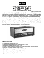
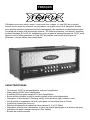
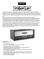
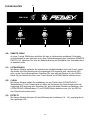
As hot as the name implies, this newest member of the Ultra
™
Tube Series rips. From its high-gain
input to paralleled speaker output jacks, the Peavey Electronics Triple XXX is not for the faint of
heart. Engineered for today’s discriminating guitarist, this amplifier is loaded with practical features
useful in real-world applications. Delivering an earth-quaking 120 Watts of pure tube power, the
Triple XXX is easily controllable thanks to a master volume pot, as well as independent volume
controls for each of its three channels. The Ultra and Crunch channels also have gain controls to
further assist in taming this beast while achieving killer sound. Tone contour is accomplished through
passive controls for Bass, Mid, and Treble on the Clean channel, while the Ultra and Crunch
channels utilize Peavey’s exclusive Bottom, Body, and Hair active controls. Designed to work
equally well into 4, 8, or 16-Ohm loads, matching this monster to a cabinet is limited only by your
imagination. With footswitchable channel and effects loop, the Triple XXX lets you keep your hands
on the guitar - and your eyes on your dream.
FEATURES
• Three 12AX7 preamp tubes
• Four 6L6GC power amp tubes driven by a 12AX7
• Power amp convertible to use four EL34 tubes
• Footswitchable effects loop with independent send and return controls
• Damping switch (Tight, Medium, Loose)
• Special noise gate circuitry on Ultra and Crunch channels
• Line out with level control
• Cabinet impedance switch (4, 8, or 16 Ohms)
• Heavy-duty power, standby and channel select toggle switches
• Classic power status indicator lamp
• Chrome-plated brass control knobs
3
ENGLISH

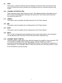
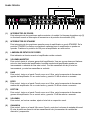
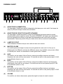
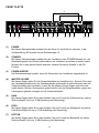
(1) POWER SWITCH
This two-way toggle switch applies mains power to the unit. The red POWER STATUS LAMP
(3) will illuminate when this switch is in the ON position.
(2) STANDBY SWITCH
This two-way toggle switch allows the amp to be placed in the STANDBY mode. In the
STANDBY position the tubes stay hot but the amplifier is not operational. Switching to the ON
position places the amp in active mode.
(3) POWER STATUS LAMP
This indicator illuminates when mains power is being supplied to the amp.
(4) MASTER VOLUME
This control sets the overall volume level of the amp. Once the desired balance between the
three channels in the amplifier has been achieved, the entire output level of the unit can be
increased or decreased by rotating this control. Clockwise rotation increases level;
counterclockwise rotation decreases level.
(5) HAIR
This control, on both the Ultra and Crunch channels, varies the high frequency response of
the amplifier. It is an active control (shelving type) and allows 15 dB of boost or cut.
(6) BODY
This control, on both the Ultra and Crunch channels, varies the mid frequency response of
the amplifier. It is an active control (peak/notch type) and allows 15 dB of boost or cut.
(7) BOTTOM
This control, on both the Ultra and Crunch channels, varies the low frequency response of the
amplifier. It is an active control (shelving type) and allows 15 dB of boost or cut.
(8) VOLUME
This control, on all three channels, sets the overall level of its respective channel.
FRONT PANEL
1 2 43 65 87 9 11 12 13 14 15
10
8
4

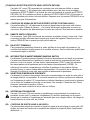
(9) GAIN
This control, on both the Ultra and Crunch channels, controls the input volume level of the
channel. Rotating this control clockwise will increase the amount of preamp distortion and
sustain.
(10) CHANNEL ACTIVATION LEDs
These indicators signify which channel is active. Ultra channel activation illuminates the red
LED; Crunch channel activation illuminates the yellow LED; and Clean channel activation
illuminates the green LED.
(11) TREBLE
This passive control regulates the high frequencies for the Clean channel.
(12) MID
This passive control regulates the mid frequencies for the Clean channel.
(13) BASS
This passive control regulates the low frequencies for the Clean channel.
(14) INPUT
This 1/4" jack is designed to accommodate most any guitar output signal. Input signal gain
can be adjusted by the GAIN (9) controls (Ultra and Crunch channels only).
(15) CHANNEL SELECT SWITCH
This three-position toggle switch allows selection between the amplifier’s three channels. LED
(10) illumination indicates which channel is active. Channel switching can also be
accomplished by footswitch. See the FOOTSWITCH section of this manual for explanation of
switch operation. The CHANNEL SELECT SWITCH must be set in the Ultra position in order
for the footswitch to operate properly.
5

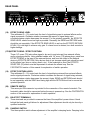
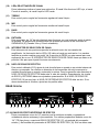
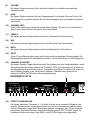
(16) EFFECTS SEND LEVEL
This calibrated (0 – 10) control sets the level of signal being sent to external effects and/or
signal processors. Clockwise rotation increases the amount of signal being sent;
counterclockwise rotation decreases the amount. For the quietest operation, the EFFECTS
SEND LEVEL should be set as high as possible. Generally, the SEND and RETURN levels
should be set oppositely. If the EFFECTS SEND LEVEL is set low, the EFFECTS RETURN
LEVEL (19) is set high to achieve unity gain. If volume boost is desired, turn both controls to
higher settings.
(17/18) EFFECTS SEND / EFFECTS RETURN
These 1/4" mono (TS) jacks allow signal to be sent to and returned from external effects
and/or signal processors. Using shielded cables with 1/4" mono (TS) phone plugs, patch from
EFFECTS SEND to the input of the external device, and from the output of the external
device to EFFECTS RETURN. Only devices that do not increase signal gain should be used
in this effects loop (chorus, delay, reverb, etc.). If the footswitch is used, the EFFECTS
SELECTOR (33) switch must be depressed to activate the effects loop. See the
FOOTSWITCH section of this manual for explanation of switch operation.
(19) EFFECTS RETURN LEVEL
This calibrated (0 – 10) control sets the level of signal being returned from external effects
and/or signal processors. Clockwise rotation increases the amount of signal being returned;
counterclockwise rotation decreases the amount. Again, SEND and RETURN levels should
be set oppositely, with the SEND level being high and the RETURN level low to ensure the
quietest operation.
(20) REMOTE SWITCH
This seven-pin DIN connector is provided for the connection of the remote footswitch. The
footswitch cable should be connected before the amp is powered up. See the FOOTSWITCH
section of this manual for explanation of switch operation.
(21) BIAS TEST TERMINALS
These terminals are provided to measure the bias of the amplifier’s power tubes. A knob
behind the back panel grill allows for adjustment. Bias adjustment should only be done by a
qualified technician.
(22) DAMPING SWITCH
This three-position switch allows adjustment of the amplifier’s damping factor. Damping is the
REAR PANEL
16 17 18 19 20 21 22 23 2524 26 28 29
27
6

ability of an amplifier to control speaker cone motion after a signal disappears. A high
damping factor (TIGHT) reduces cone vibration quicker than a low (LOOSE) factor. This
switch works much like the resonance and presence controls on other Peavey amps, if those
controls were turned simultaneously. If the DAMPING SWITCH is changed, the volume of the
amp will also change and require re-adjustment.
(23) CABINET IMPEDANCE SWITCH
This three-position switch allows appropriate selection of speaker cabinet impedance. If two
enclosures of equal impedance are used, the switch should be set to half the individual value.
For example, two 16-Ohm enclosures necessitate an 8-Ohm setting, while two 8-Ohm
enclosures would require a 4-Ohm setting. Minimum speaker impedance is 4 Ohms.
(24) SPEAKER OUTPUTS
These paralleled 1/4" mono (TS) jacks are provided for the connection of speaker
enclosure(s). Again, minimum speaker impedance is 4 Ohms. The CABINET IMPEDANCE
SWITCH (23) should be set to match the load of the speaker cabinet(s).
(25) LINE OUT LEVEL
This control sets the level of signal being sent out of the LINE OUT (26) jack. It may be used
to balance the level of slave power amp/speaker systems driven from the LINE OUT (26) to
the level of cabinets driven from the SPEAKER OUTPUTS (24).
(26) LINE OUT
This 1/4" mono (TS) jack provides a post-power amp signal to drive another power
amp/speaker system while maintaining the amplifier’s tone.
(27) FUSE
A fuse is located within the cap of the fuse holder. This fuse must be replaced with one of the
same type and value to avoid damaging the amplifier and voiding the warranty. If the amp
repeatedly blows the fuse, it should be taken to a qualified service center for repair.
WARNING: THE FUSE SHOULD ONLY BE REPLACED AFTER THE POWER CORD HAS
BEEN DISCONNECTED.
(28) GROUND POLARITY SWITCH
This three-position, rocker-type switch should normally be placed in the center (0) position. If
hum or noise is noticed coming from the speaker enclosure(s), the switch may be placed in
the “+” or “-” position to minimize hum/noise. If changing the polarity does not alleviate the
problem, consult your authorized Peavey dealer, the Peavey factory, or a qualified service
technician.
(29) IEC MAINS CONNECTOR
This is a standard IEC power connector. An AC mains cord having the appropriate AC plug
and ratings for the intended operating voltage is included in the carton. The mains cord
should be connected to the amplifier before connecting to a suitable AC outlet.
U.S DOMESTIC AC MAINS CORD
The mains cord supplied with the unit is a heavy-duty, 3-conductor type with a conventional
120 VAC plug with ground pin. If the outlet used does not have a ground pin, a suitable
grounding adapter should be used, and the third wire should be grounded properly.
Never break off the ground pin on any equipment. It is provided for your safety.
7

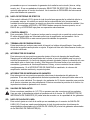
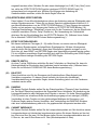
(30) CABLE CONNECTOR
This 7-pin DIN connector is provided for connecting the footswitch to the amplifier REMOTE
SWITCH (20) via the cable included in the carton. Connections at the switch and the amplifier
should be made before the amp is powered up.
(31) ULTRA / CRUNCH SELECTOR
This switch selects between the Ultra and Crunch channels on the amplifier. The adjacent
LED will illuminate when the Ultra channel is selected. When the LED is dark, the Crunch
channel is selected. The CLEAN SELECTOR (32) must be in the BYPASS mode to activate
either the Ultra or Crunch channel.
(32) CLEAN SELECTOR
This switch selects the Clean channel and will activate regardless of the position of the
ULTRA / CRUNCH SELECTOR (31). The adjacent LED will illuminate when the Clean
channel is selected. This switch must be in the BYPASS position, indicated by a dark LED, in
order to utilize the ULTRA / CRUNCH SELECTOR (31).
(33) EFFECTS SELECTOR
This switch activates the amplifier’s effects loop (16 – 19). The adjacent LED will illuminate
when the effects loop is active.
FOOTSWITCH
30
8
NOTE: FOR UK ONLY
If the colors of the wires in the mains lead of this unit do not correspond with the colored markings
identifying the terminals in your plug, proceed as follows: (1) The wire that is colored green and
yellow must be connected to the terminal that is marked by the letter E, the earth symbol, colored
green, or colored green and yellow. (2) The wire that is colored blue must be connected to the
terminal that is marked with the letter N or the color black. (3) The wire that is colored brown must
be connected to the terminal that is marked with the letter L or the color red.
31 32 33

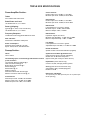
Power Amplifier Section:
Tubes:
Four 6L6GCs with 12AX7 driver
Rated Power and Load:
120 W RMS into 16, 8, or 4 Ohms
Power @ Clipping:
(typically @ 5% THD, 1 kHz, 120 VAC line)
120 W RMS into 16, 8, or 4 Ohms
Frequency Response:
±3 dB 50 Hz to 20 kHz @ 90 W RMS into 8 Ohms
Hum and Noise:
Greater than 76 dB below rated power
Power Consumption:
Domestic: 400 W, 50/60 Hz, 120 VAC
Export: 400 W, 60 Hz, 220-230/240 VAC
Preamp Section:
Tubes:
Three 12AX7s
The following specs are measured @ 1 kHz with the controls
preset as follows:
Low and High EQ @ 10, Mid EQ @ 0
Ultra and Crunch Posts @ 10
Bottom, Body, and Hair EQ @ 5
Effects Send @ 0
Effects Return @ 10
Master Level @ 5
Nominal Levels are with Pre Gain @ 5
Minimum Levels are with Pre Gain @ 10
Clean Channel:
Nominal Input Level: -20 dBV, 100 mV RMS
Minimum Input Level: -30 dBV, 30 mV RMS
Maximum Input Level: 0 dBV, 1.0 mV RMS
Crunch Channel:
Nominal Input Level: -80 dBV, 0.1 mV RMS
Minimum Input Level: -90 dBV, 0.03 mV RMS
Ultra Channel:
Nominal Input Level: -80 dBV, 0.1 mV RMS
Minimum Input Level: -90 dBV, 0.03 mV RMS
Effects Send:
Load Impedance: 47 k Ohms or greater
Minimum Output: -10 dBV, 300 mV RMS
Maximum Output: 0 dBV, 1 V RMS
Effects Return:
Impedance: High-Z, 80 k Ohms
Minimum Input Sensitivity: -10 dBV, 300 mV RMS
Maximum Input Sensitivity: 0 dBV, 1 V RMS
Line Output:
Load Impedance: 47 k Ohms or greater
Adjustable Output: ±20 dBV, 0.1 V RMS-10 V RMS
Remote Footswitch:
Special 3-button unit with LED indicators (supplied)
System Hum and Noise @ Nominal Level:
(Clean channel, 20 Hz to 20 kHz unweighted)
Greater than 74 dB below rated power
(Special noise gate circuitry for Ultra & Crunch)
Equalization: (Clean channel only)
Custom Low, Mid, and High passive type EQ
Voicing: (Ultra and Crunch channels only)
Active Bottom, Body, and Hair (Edge) EQ
Boost/Cut ±12 dB
Dimensions and Weight:
11.0" (279 mm) H x 26.5" (673 mm) W x 11.0" (279 mm) D
52 lbs. (23.6 kg)
TRIPLE XXX SPECIFICATIONS
9

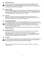
10
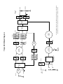
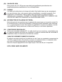
This block diagram shows the signal path within the unit. In order to thoroughly
understand the unit's functions, please study the block diagram carefully.
TUBE
STAGE
SWITCH
LOGIC
RETURN
SEND
F.S.W
CHANNEL
ULTRA
TUBE
STAGES
SWITCH
LOGIC
FX LOOP
BYPASS
EFFECTS
LOOP
VOICING
INPUT
BOT. BODY HAIR
BOT. BODY HAIR
ULTRA
CLEAN
TUBE
STAGE
CLEAN
BASS MID TREBLE
MASTER
VOLUME
TUBE
STAGES
TUBE
POWER AMP
IMPEDANCE
SWITCH
SEND
RETURN
LEVEL
LINE
OUT
CRUNCH
PRE
PRE
POST
POST
CRUNCH
PRE
DAMPING
SWITCH
4Ω 8 Ω 16 Ω
Triple XXX Block Diagram
Page is loading ...
Page is loading ...
Page is loading ...
Page is loading ...
Page is loading ...
Page is loading ...
Page is loading ...
Page is loading ...
Page is loading ...
Page is loading ...
Page is loading ...
Page is loading ...
Page is loading ...

24
Power Amplifier Section:
Tubes:
Four 6L6GCs with 12AX7 driver
Rated Power and Load:
120 W RMS into 16, 8, or 4 Ohms
Power @ Clipping:
(typically @ 5% THD, 1 kHz, 120 V AC line)
120 W RMS into 16, 8, or 4 Ohms
Frequency Response:
±3 dB 50 Hz to 20 kHz @ 90 W RMS into 8 Ohms
Hum and Noise:
Greater than 76 dB below rated power
Power Consumption:
Domestic: 400 W, 50/60 Hz, 120 V AC
Export: 400 W, 60 Hz, 220-230/240 V AC
Preamp Section:
Tubes:
Three 12AX7s
The following specs are measured @ 1 kHz with the controls
preset as follows:
Low and High EQ @ 10, Mid EQ @ 0
Ultra and Crunch Posts @ 10
Bottom, Body, and Hair EQ @ 5
Effects Send @ 0
Effects Return @ 10
Master Level @ 5
Nominal Levels are with Pre Gain @ 5
Minimum Levels are with Pre Gain @ 10
Clean Channel:
Nominal Input Level: -20 dBV, 100 mV RMS
Minimum Input Level: -30 dBV, 30 mV RMS
Maximum Input Level: 0 dBV, 1.0 mV RMS
Crunch Channel:
Nominal Input Level: -80 dBV, 0.1 mV RMS
Minimum Input Level: -90 dBV, 0.03 mV RMS
Ultra Channel:
Nominal Input Level: -80 dBV, 0.1 mV RMS
Minimum Input Level: -90 dBV, 0.03 mV RMS
Effects Send:
Load Impedance: 47 k Ohms or greater
Minimum Output: -10 dBV, 300 mV RMS
Maximum Output: 0 dBV, 1 V RMS
Effects Return:
Impedance: High-Z, 80 k Ohms
Minimum Input Sensitivity: -10 dBV, 300 mV RMS
Maximum Input Sensitivity: 0 dBV, 1 V RMS
Line Output:
Load Impedance: 47 k Ohms or greater
Adjustable Output: ±20 dBV, 0.1V RMS-10 V RMS
Remote Footswitch:
Special 3-button unit with LED indicators (supplied)
System Hum and Noise @ Nominal Level:
(Clean channel, 20 Hz to 20 kHz unweighted)
Greater than 74 dB below rated power
(Special noise gate circuitry for Ultra & Crunch)
Equalization: (Clean channel only)
Custom Low, Mid, and High passive type EQ
Voicing: (Ultra and Crunch channels only)
Active Bottom, Body, and Hair (Edge) EQ
Boost/Cut ±12 dB
Dimensions and Weight:
11.0" (279 mm) H x 26.5" (673 mm) W x 11.0" (279 mm) D
52 lbs. (23.6 kg)
SPECIFICATIONS
Page is loading ...
Page is loading ...
Page is loading ...
Page is loading ...
Page is loading ...
Page is loading ...
Page is loading ...
Page is loading ...
Page is loading ...

34
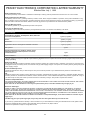
PEAVEY ELECTRONICS CORPORATION LIMITED WARRANTY
Effective Date: July 1, 1998
What This Warranty Covers
Your Peavey Warranty covers defects in material and workmanship in Peavey products purchased and serviced in the U.S.A. and Canada.
What This Warranty Does Not Cover
The Warranty does not cover: (1) damage caused by accident, misuse, abuse, improper installation or operation, rental, product modification or neg-
lect; (2) damage occurring during shipment; (3) damage caused by repair or service performed by persons not authorized by Peavey; (4) products on
which the serial number has been altered, defaced or removed; (5) products not purchased from an Authorized Peavey Dealer.
Who This Warranty Protects
This Warranty protects only the original retail purchaser of the product.
How Long This Warranty Lasts
The Warranty begins on the date of purchase by the original retail purchaser. The duration of the Warranty is as follows:
Product Category Duration
Guitars/Basses, Amplifiers, Pre-Amplifiers, Mixers, Electronic
Crossovers and Equalizers 2 years *(+ 3 years)
Drums 2 years *(+ 1 year)
Enclosures 3 years *(+ 2 years)
Digital Effect Devices and Keyboard and MIDI Controllers 1 year *(+ 1 year)
Microphones 2 years
Speaker Components (incl. speakers, baskets, drivers,
diaphragm replacement kits and passive crossovers)
and all Accessories 1 year
Tubes and Meters 90 days
[*Denotes additional warranty period applicable if optional Warranty Registration Card is completed and returned to Peavey by original retail purchaser within
90 days of purchase.]
What Peavey Will Do
We will repair or replace (at Peavey's discretion) products covered by warranty at no charge for labor or materials. If the product or component must
be shipped to Peavey for warranty service, the consumer must pay initial shipping charges. If the repairs are covered by warranty, Peavey will pay the
return shipping charges.
How To Get Warranty Service
(1) Take the defective item and your sales receipt or other proof of date of purchase to your Authorized Peavey Dealer or Authorized Peavey
Service Center.
OR
(2) Ship the defective item, prepaid, to Peavey Electronics Corporation, International Service Center, 412 Highway 11 & 80 East, Meridian, MS 39301
or Peavey Canada Ltd., 95 Shields Court, Markham, Ontario, Canada L3R 9T5. Include a detailed description of the problem, together with a copy of
your sales receipt or other proof of date of purchase as evidence of warranty coverage. Also provide a complete return address.
Limitation of Implied Warranties
ANY IMPLIED WARRANTIES, INCLUDING WARRANTIES OF MERCHANTABILITY AND FITNESS FOR A PARTICULAR PURPOSE, ARE LIMITED
IN DURATION TO THE LENGTH OF THIS WARRANTY.
Some states do not allow limitations on how long an implied warranty lasts, so the above limitation may not apply to you.
Exclusions of Damages
PEAVEY'S LIABILITY FOR ANY DEFECTIVE PRODUCT IS LIMITED TO THE REPAIR OR REPLACEMENT OF THE PRODUCT, AT PEAVEY'S
OPTION. IF WE ELECT TO REPLACE THE PRODUCT, THE REPLACEMENT MAY BE A RECONDITIONED UNIT. PEAVEY SHALL NOT BE
LIABLE FOR DAMAGES BASED ON INCONVENIENCE, LOSS OF USE, LOST PROFITS, LOST SAVINGS, DAMAGE TO ANY OTHER EQUIPMENT
OR OTHER ITEMS AT THE SITE OF USE, OR ANY OTHER DAMAGES WHETHER INCIDENTAL, CONSEQUENTIAL OR OTHERWISE, EVEN IF
PEAVEY HAS BEEN ADVISED OF THE POSSIBILITY OF SUCH DAMAGES.
Some states do not allow the exclusion or limitation of incidental or consequential damages, so the above limitation or exclusion may not
apply to you.
This Warranty gives you specific legal rights, and you may also have other rights which vary from state to state.
If you have any questions about this warranty or service received or if you need assistance in locating an Authorized Service Center, please contact
the Peavey International Service Center at (601) 483-5365 / Peavey Canada Ltd. at (905) 475-2578.
Features and specifications subject to change without notice.

35
IMPORTANT SAFETY INSTRUCTIONS
WARNING: When using electric products, basic cautions should always be followed, including the following:
1. Read all safety and operating instructions before using this product.
2. All safety and operating instructions should be retained for future reference.
3. Obey all cautions in the operating instructions and on the back of the unit.
4. All operating instructions should be followed.
5. This product should not be used near water (i.e., a bathtub, sink, swimming pool, wet basement, etc.)
6. This product should be located so that its position does not interfere with its proper ventilation. It should not be placed flat against a wall
or placed in a built-in enclosure that will impede the flow of cooling air.
7. This product should not be placed near a source of heat such as a stove, radiator, or another heat producing amplifier.
8. Connect only to a power supply of the type marked on the unit adjacent to the power supply cord.
9. Never break off the ground pin on the power supply cord. For more information on grounding, write
for our free booklet “Shock Hazard and Grounding."
10. Power supply cords should always be handled carefully. Never walk on or place equipment on power supply cords. Periodically check cords
for cuts or signs of stress, especially at the plug and the point where the cord exits the unit.
11. The power supply cord should be unplugged when the unit is to be unused for long periods of time.
12. If this product is to be mounted in an equipment rack, rear support should be provided.
13. Metal parts can be cleaned with a damp rag. The vinyl covering used on some units can be cleaned with a damp rag or an ammonia-based
household cleaner if necessary. Disconnect unit from power supply before cleaning.
14. Care should be taken so that objects do not fall and liquids are not spilled into the unit through the ventilation holes or any other openings.
15. This unit should be checked by a qualified service technician if:
a. The power supply cord or plug has been damaged.
b. Anything has fallen or been spilled into the unit.
c. The unit does not operate correctly.
d.The unit has been dropped or the enclosure damaged.
16. The user should not attempt to service this equipment. All service work should be done by a qualified service technician.
17. This product should be used only with a cart or stand that is recommended by Peavey Electronics.
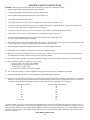
18. Exposure to extremely high noise levels may cause a permanent hearing loss. Individuals vary considerably in susceptibility to noise induced
hearing loss, but nearly everyone will lose some hearing if exposed to sufficiently intense noise for a sufficient time. The U.S. Government’s
Occupational Safety and Health Administration (OSHA) has specified the following permissible noise level exposures.
Duration Per Day In Hours Sound Level dBA, Slow Response
890
692
495
397
2 100
1 1/2 102
1 105
1/2 110
1/4 or less 115
According to OSHA, any exposure in excess of the above permissible limits could result in some hearing loss. Ear plugs or protectors for the ear
canals or over the ears must be worn when operating this amplification system in order to prevent a permanent hearing loss if exposure is in excess
of the limits as set forth above. To ensure against potentially dangerous exposure to high sound pressure levels, it is recommended that all persons
exposed to equipment capable of producing high sound pressure levels such as this amplification system be protected by hearing protectors while
this unit is in operation.
SAVE THESE INSTRUCTIONS!

Features and specifications subject to change without notice.
Peavey Electronics Corporation • 711 A Street • Meridian • MS • 39301
(601) 483-5365 • FAX (601) 486-1278 • www.peavey.com
©2001 Printed in the U.S.A. 7/01
80304881
-
 1
1
-
 2
2
-
 3
3
-
 4
4
-
 5
5
-
 6
6
-
 7
7
-
 8
8
-
 9
9
-
 10
10
-
 11
11
-
 12
12
-
 13
13
-
 14
14
-
 15
15
-
 16
16
-
 17
17
-
 18
18
-
 19
19
-
 20
20
-
 21
21
-
 22
22
-
 23
23
-
 24
24
-
 25
25
-
 26
26
-
 27
27
-
 28
28
-
 29
29
-
 30
30
-
 31
31
-
 32
32
-
 33
33
-
 34
34
-
 35
35
-
 36
36


Peavey Triple XXX Owner's manual
- Category
- Musical Instrument Amplifier
- Type
- Owner's manual
Ask a question and I''ll find the answer in the document
Finding information in a document is now easier with AI
in other languages
Related papers
-
Peavey JSX Guitar Amplifier User manual
-
-
-
-
-
-
-
-
-
Other documents
-
Engl Z5 Footswitch Owner's manual
-
Koch STUDIOTONE Operating Instructions Manual
-
 Laboga The Beast 30W Plus - head User manual
-
Hughes & Kettner TrilogyTM User manual
-
AER BasicPerformer2 Owner's manual
-
Hartke GT100 User manual
-
Evh 5150-III Owner's manual
-
Blackstar HT METAL 100 Owner's manual
-
Omnitronic COMBO-70 User manual
-
