Page is loading ...

Date last updated:08-17-2022
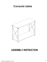
Console table

a b c d e
f g h
14 PCS 14 PCS 12 PCS 6 PCS 16 PCS
2 PCS
kl
8 PCS 2 PCS 2 PCS 2 PCS
2 PCS 24 PCS
2
3
4
5
6
x2
10
11
12
13
14
x2
x2
x2
1
9
7
8
15
16
17
i j
h h
h
pr
n o
m
4 PCS2 PCS4 PCS
4 PCS2 PCS2 PCS2 PCS
4 PCS
q
1 PC

bx8
ex8
ax8
e
e
e
e
10
11
12
13
12
x2
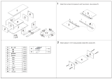
Fix parts 10 and 11 to part 12 using screws (e), as shown.
Place part 13 into grooves between parts 10, 11 and 12, as shown.
a
a
DL
DR
10
11
f
i
16
16
fx2
ix12
hx2
a
a
DL
DR
14
14
10
11
f
b
hx2
Fix handles (f) to parts 14 and 16 using screws (i), as shown.
Insert quickfit screws (a) into parts 14 and 16, as shown.
Insert cam locks (b) into parts 10 and 11, as shown.
Fit parts 14 and 16 to parts 10 and 11.Turn cam locks clockwise to tighten.
Fix inner drawer runners (DR) and (DL) to assembled drawers using screws (i), as shown.
i
i
i
i
i
i
i
i
i
i
i
i
b
b
b
i

Fix parts 2, 3 and 4 to part 6 using wooden dowels (c) and screws (e), as shown.
cx6
ex6
4
CR
2
CL
3
CR
3
CL
ix12
hx2
hx2
Fix outer drawer runners (CL) and (CR) to parts 2 and 4, as shown.
Fix outer drawer runners (CL) and (CR) to the both two sides of part 3 using screws (i), as shown.
2
3
4
6
C
C
C
C
C
C
e
e
e
e
e
e
i
i i i i
i
i
i
i
i
i
i i
i
i

Slide part 5 into grooves between parts 2, 6 and 4, as shown.
5
a
a
C
C
a
a
C
C
a
a
C
C
1
bx6
ax6
cx6
Insert quickfit screws (A) into part 1, as shown.
Insert cam locks (b) and wooden dowels (c) into parts 2, 3 and 4, as shown.
Fit part 1 to parts 2, 3 and 4.Turn cam locks clockwise to tighten.
b
b
b
b
b
b
2
3
4
2
3
4
6
6

gx8
dx6
9
7
15
8
d
d
d
d
d
d
17
rx1
Fix parts 8, 9 and 15 to parts 7 and 17 using screws (d) and allen key (r), as shown.
r
g
p
gg
gg
g
p
15
px2
qx4
q
q
q
q
r
Fix assembled legs to part 6 using screws (g), as shown.
Fix connecting brace (p) to part 15 with parts 7 and 17 using screws (q) and allen key, as shown.
7
17
8

STEP 9.
STEP 10.
m
m
mx4
jx4
m
m
j
j
Fix corner brackets (m) to part 5 using screws (j), as shown.
14
k
16
Fit drawers into assembled unit, as shown.
Fix wall starps (K) on to part 1 using screws (n) and washers (l), as shown.
l
n
k
l
n
5
nx2
kx2
lx2

STEP 11.
ox2
ex2
lx2
e
e
o
ol
l
For extra stability, you must fix your Console table to the wall using hardwares (e, l and o), as shown.
Screws (e) are fixed through wall straps and washers (l) and into the wall plugs (o).
Should you choose not to affix the product to the wall,
serious injury may be caused if the product tips over.
/


