Honda GX200UT2QX2 Owner's manual

Type
Owner's manual
ENGLISH 1
ENGLISHFRANÇAISESPAÑOL
INTRODUCTION
Thank you for purchasing a Honda engine. We want to help you to
get the best results from your new engine and to operate it safely.
This manual contains information on how to do that; please read it
carefully before operating the engine. If a problem should arise, or if
you have any questions about your engine, consult an authorized
Honda servicing dealer.
All information in this publication is based on the latest product
information available at the time of printing. Honda Motor Co., Ltd.
reserves the right to make changes at any time without notice and
without incurring any obligation. No part of this publication may be
reproduced without written permission.
This manual should be considered a permanent part of the engine
and should remain with the engine if resold.
Review the instructions provided with the equipment powered by
this engine for any additional information regarding engine startup,
shutdown, operation, adjustments or any special maintenance
instructions.
United States, Puerto Rico, and U.S. Virgin Islands:
We suggest you read the warranty policy to fully understand its
coverage and your responsibilities of ownership. The warranty
policy is a separate document that should have been given to you
by your dealer.
SAFETY MESSAGES
Your safety and the safety of others are very important. We have
provided important safety messages in this manual and on the
engine. Please read these messages carefully.
A safety message alerts you to potential hazards that could hurt
you or others. Each safety message is preceded by a safety alert
symbol and one of three words, DANGER, WARNING, or
CAUTION.
Each message tells you what the hazard is, what can happen, and
what you can do to avoid or reduce injury.
DAMAGE PREVENTION MESSAGES
You will also see other important messages that are preceded by
the word NOTICE.
The purpose of these messages is to help prevent damage to your
engine, other property, or the environment.
©2012 Honda Motor Co., Ltd. –All Rights Reserved
GX120UT2·GX160UT2·GX200UT2
·GX120RT2·GX160RT2·GX200RT2
37Z4HA00
00X37-Z4H-A000
These signal words mean:
You WILL be KILLED or SERIOUSLY
HURT if you don’t follow instructions.
You CAN be KILLED or SERIOUSLY
HURT if you don’t follow instructions.
You CAN be HURT if you don’t follow
instructions.
This word means:
Your engine or other property can be damaged if you
don’t follow instructions.
OWNER’S MANUAL
MANUEL DE L’UTILISATEUR
MANUAL DEL PROPIETARIO
GX120 • GX160 • GX200
CONTENTS
The engine exhaust from this product
contains chemicals known to the State of
California to cause cancer, birth defects
or other reproductive harm.
INTRODUCTION .................... 1
SAFETY MESSAGES .............. 1
SAFETY INFORMATION.......... 2
SAFETY LABEL LOCATIONS.... 2
COMPONENT & CONTROL
LOCATIONS .......................... 3
FEATURES ............................ 3
BEFORE OPERATION
CHECKS............................... 4
OPERATION.......................... 4
SAFE OPERATING
PRECAUTIONS ................... 4
STARTING THE ENGINE....... 4
STOPPING THE ENGINE ...... 6
SETTING ENGINE SPEED..... 6
SERVICING YOUR ENGINE...... 7
THE IMPORTANCE OF
MAINTENANCE.................. 7
MAINTENANCE SAFETY ..... 7
SAFETY PRECAUTIONS....... 7
MAINTENANCE
SCHEDULE ........................ 7
REFUELING........................ 8
ENGINE OIL ....................... 8
Recommended Oil............ 8
Oil Level Check................ 9
Oil Change...................... 9
REDUCTION CASE OIL ........ 9
Recommended Oil............ 9
Oil Level Check................ 9
Oil Change.....................10
AIR CLEANER ...................10
Inspection......................10
Cleaning........................11
SEDIMENT CUP................12
SPARK PLUG ....................12
SPARK ARRESTER ............13
IDLE SPEED......................13
HELPFUL TIPS &
SUGGESTIONS....................13
STORING YOUR ENGINE ....13
TRANSPORTING ...............14
TA KI N G CA R E O F
UNEXPECTED PROBLEMS .....15
FUSE REPLACEMENT ........15
TECHNICAL INFORMATION....16
Serial Number Location ...16
Battery Connections for
Electric Starter...............16
Remote Control Linkage ...16
Carburetor Modifications for
High Altitude Operation.....17
Emission Control System
Information ...................17
Air Index.......................18
Specifications................18
Tuneup Specifications .....19
Quick Reference
Information ...................19
Wiring Diagrams.............19
CONSUMER INFORMATION ... 20
Warranty and Distributor/
Dealer Locator
Information ...................20
Customer Service
Information ...................20
32Z4HA00.fm 1 ページ 2012年7月11日 水曜日 午前10時3分
2ENGLISH
SAFETY INFORMATION
Understand the operation of all controls and learn how to stop the
engine quickly in case of emergency. Make sure the operator
receives adequate instruction before operating the equipment.
Do not allow children to operate the engine. Keep children and
pets away from the area of operation.
Your engine’s exhaust contains poisonous carbon monoxide.
Do not run the engine without adequate ventilation, and never
run the engine indoors.
The engine and exhaust become very hot during operation.
Keep the engine at least 1 meter (3 feet) away from buildings and
other equipment during operation. Keep flammable materials
away, and do not place anything on the engine while it is running.
SAFETY LABEL LOCATIONS
These labels warn you of potential hazards that can cause serious
injury. Read them carefully.
If a label comes off or becomes hard to read, contact your Honda
servicing dealer for a replacement label.
WARNING LABEL For EU Except EU
attached to
product
supplied with
product
supplied with
product
attached to
product
supplied with
product
supplied with
product
MUFFLER CAUTION LABEL For EU Except EU
not
included
supplied
with product
supplied
with product
attached to
product
supplied
with product
supplied with
product
Gasoline is highly flammable and explosive.
Stop the engine and let cool before refueling.
The engine emits toxic poisonous carbon
monoxide gas. Do not run in an enclosed area.
Read Owner’s Manual before operation.
Hot muffler can burn you.
Stay away if engine has been running.
MUFFLER CAUTION LABEL
WARNING LABEL
32Z4HA00.fm 2 ページ 2012年7月11日 水曜日 午前10時3分
ENGLISH 3
COMPONENT & CONTROL LOCATIONS
FUEL FILLER CAP
FUEL TANK
OIL DRAIN PLUG
ELECTRIC STARTER
(applicable type)
OIL FILLER CAP/DIPSTICK
RECOIL STARTER
AIR CLEANER
MUFFLER
SPARK PLUG
STARTER GRIP
ENGINE CONTROL TYPES
FUEL VALVE LEVER
CHOKE LEVER
EXCEPT ELECTRIC
STARTER TYPES
ENGINE SWITCH
THROTTLE LEVER
CHOKE LEVER
(air cleaner low profile type)
ENGINE SWITCH
ELECTRIC STARTER TYPES
ENGINE SWITCH
CIRCUIT PROTECTOR
FEATURES
OIL ALERT® SYSTEM (applicable types)
‘‘Oil Alert is a registered trademark in the United States’’
The Oil Alert system is designed to prevent engine damage caused
by an insufficient amount of oil in the crankcase. Before the oil level
in the crankcase can fall below a safe limit, the Oil Alert system will
automatically stop the engine (the engine switch will remain in the
ON position).
If the engine stops and will not restart, check the engine oil level
(see page 9) before troubleshooting in other areas.
CIRCUIT PROTECTOR (applicable types)
The circuit protector protects the
battery charging circuit. A short
circuit, or a battery connected with
reverse polarity, will trip the circuit
protector.
The green indicator inside the circuit
protector will pop out to show that the
circuit protector has switched off. If
this occurs, determine the cause of the
problem, and correct it before resetting
the circuit protector.
Push the circuit protector button to
reset.
CIRCUIT
PROTECTOR
ON
OFF
32Z4HA00.fm 3 ページ 2012年7月11日 水曜日 午前10時3分
4ENGLISH
BEFORE OPERATION CHECKS
IS YOUR ENGINE READY TO GO?
For your safety, to ensure compliance with environmental
regulations, and to maximize the service life of your equipment, it is
very important to take a few moments before you operate the
engine to check its condition. Be sure to take care of any problem
you find, or have your servicing dealer correct it, before you operate
the engine.
Before beginning your pre-operation checks, be sure the engine is
level and the engine switch is in the OFF position.
Always check the following items before you start the engine:
Check the General Condition of the Engine
1. Look around and underneath the engine for signs of oil or
gasoline leaks.
2. Remove any excessive dirt or debris, especially around the
muffler and recoil starter.
3. Look for signs of damage.
4. Check that all shields and covers are in place, and all nuts, bolts,
and screws are tightened.
Check the Engine
1. Check the fuel level (see page 8). Starting with a full tank will
help to eliminate or reduce operating interruptions for refueling.
2. Check the engine oil level (see page 9). Running the engine with
a low oil level can cause engine damage.
The Oil Alert system (applicable types) will automatically stop
the engine before the oil level falls below safe limits. However, to
avoid the inconvenience of an unexpected shutdown, always
check the engine oil level before startup.
3. Check the reduction case oil level on applicable types (see page
9). Oil is essential to reduction case operation and long life.
4. Check the air filter element (see page 10). A dirty air filter
element will restrict air flow to the carburetor, reducing engine
performance.
5. Check the equipment powered by this engine.
Review the instructions provided with the equipment powered
by this engine for any precautions and procedures that should
be followed before engine startup.
Improperly maintaining this engine, or failure to
correct a problem before operation, can cause a
malfunction in which you can be seriously hurt or
killed.
Always perform a pre-operation inspection before
each operation, and correct any problem.
OPERATION
SAFE OPERATING PRECAUTIONS
Before operating the engine for the first time, please review the
SAFETY INFORMATION section on page 2 and the BEFORE
OPERATION CHECKS on page 4.
For your safety, do not operate the engine in an enclosed area such
as a garage. Your engine’s exhaust contains poisonous carbon
monoxide gas that can collect rapidly in an enclosed area and cause
illness or death.
Review the instructions provided with the equipment powered by
this engine for any safety precautions that should be observed with
engine startup, shutdown, or operation.
Do not operate the engine on slopes greater than 20° (36%).
STARTING THE ENGINE
1. Move the fuel valve lever to the ON position.
2. To start a cold engine, move the choke lever to the CLOSED
position.
To restart a warm engine, leave the choke lever in the OPEN
position.
Some engine applications use a remote-mounted choke control
rather than the engine-mounted choke lever shown here. Refer
to the instructions provided by the equipment manufacturer.
Exhaust contains poisonous carbon monoxide gas
that can build up to dangerous levels in closed areas.
Breathing carbon monoxide can cause
unconsciousness or death.
Never run the engine in a closed, or even partly closed
area where people may be present.
FUEL VALVE LEVER
ON OFF ON
CHOKE LEVER
CLOSED
CLOSED
OPEN
32Z4HA00.fm 4 ページ 2012年7月11日 水曜日 午前10時3分
ENGLISH 5
3. Move the throttle lever away from the MIN. position, about 1/3
of the way toward the MAX. position.
Some engine applications use a remote-mounted throttle control
rather than the engine-mounted throttle lever shown here. Refer
to the instructions provided by the equipment manufacturer.
4. Turn the engine switch to the ON position.
THROTTLE LEVER
MAX. MIN.
1/3 POSITION
MIN.
EXCEPT ELECTRIC
STARTER TYPES
ELECTRIC STARTER TYPES
ON
ENGINE SWITCH
ON
ON
ENGINE SWITCH
ENGINE SWITCH
ON
ON
ON
5. Operate the starter.
RECOIL STARTER:
Pull the starter grip lightly until you feel resistance, then pull
briskly in the direction of the arrow as shown below. Return the
starter grip gently.
Do not allow the starter grip to snap back against the engine.
Return it gently to prevent damage to the starter.
ELECTRIC STARTER (applicable types):
Turn the key to the START position,
and hold it there until the engine
starts.
If the engine fails to start within 5
seconds, release the key, and wait at
least 10 seconds before operating the
starter again.
Using the electric starter for more
than 5 seconds at a time will overheat
the starter motor and can damage it.
This type of overheating is not
covered under warranty.
When the engine starts, release the
key, allowing it to return to the ON
position.
6. If the choke lever was moved to the CLOSED position to start
the engine, gradually move it to the OPEN position as the engine
warms up.
STARTER GRIP
Direction to pull
START
START
ENGINE SWITCH
(applicable types)
32Z4HA00.fm 5 ページ 2012年7月11日 水曜日 午前10時3分
6ENGLISH
STOPPING THE ENGINE
To stop the engine in an emergency, simply turn the engine switch
to the OFF position. Under normal conditions, use the following
procedure. Refer to the instructions provided by the equipment
manufacturer.
1. Move the throttle lever to the MIN. position.
Some engine applications use a remote-mounted throttle control
rather than the engine-mounted throttle lever shown here.
2. Turn the engine switch to the OFF position.
3. Move the fuel valve lever to the OFF position.
THROTTLE LEVER
MIN.
MIN.
EXCEPT ELECTRIC
STARTER TYPES
ELECTRIC STARTER TYPES
OFF
ENGINE SWITCH
OFF
OFF
OFF
OFF
ENGINE
SWITCH
ENGINE SWITCH
OFF
FUEL VALVE LEVER
OFF
OFF ON
SETTING ENGINE SPEED
Position the throttle lever for the desired engine speed.
Some engine applications use a remote-mounted throttle control
rather than the engine-mounted throttle lever shown here. Refer to
the instructions provided by the equipment manufacturer.
For engine speed recommendations, refer to the instructions
provided with the equipment powered by this engine.
THROTTLE LEVER
MAX. MIN.
MAX.
MIN.
32Z4HA00.fm 6 ページ 2012年7月11日 水曜日 午前10時3分
ENGLISH 7
SERVICING YOUR ENGINE
THE IMPORTANCE OF MAINTENANCE
Good maintenance is essential for safe, economical, and
trouble-free operation. It will also help reduce pollution.
To help you properly care for your engine, the following pages
include a maintenance schedule, routine inspection procedures, and
simple maintenance procedures using basic hand tools. Other
service tasks that are more difficult, or require special tools, are
best handled by professionals and are normally performed by a
Honda technician or other qualified mechanic.
The maintenance schedule applies to normal operating conditions.
If you operate your engine under severe conditions, such as
sustained high-load or high-temperature operation, or use in
unusually wet or dusty conditions, consult your servicing dealer for
recommendations applicable to your individual needs and use.
Maintenance, replacement, or repair of the emission control
devices and systems may be performed by any engine repair
establishment or individual, using parts that are ‘‘certified’’ to EPA
standards.
MAINTENANCE SAFETY
Some of the most important safety precautions follow. However,
we cannot warn you of every conceivable hazard that can arise in
performing maintenance. Only you can decide whether or not you
should perform a given task.
SAFETY PRECAUTIONS
Make sure the engine is off before you begin any maintenance or
repairs. To prevent accidental startup, disconnect the spark plug
cap. This will eliminate several potential hazards:
Carbon monoxide poisoning from engine exhaust.
Operate outside, away from open windows or doors.
Burns from hot parts.
Let the engine and exhaust system cool before touching.
Injury from moving parts.
Do not run the engine unless instructed to do so.
Read the instructions before you begin, and make sure you have
the tools and skills required.
To reduce the possibility of fire or explosion, be careful when
working around gasoline. Use only a non-flammable solvent, not
gasoline, to clean parts. Keep cigarettes, sparks and flames away
from all fuel related parts.
Remember that an authorized Honda servicing dealer knows your
engine best and is fully equipped to maintain and repair it.
To ensure the best quality and reliability, use only new Honda
Genuine parts or their equivalents for repair and replacement.
Improper maintenance, or failure to correct a problem
before operation, can cause a malfunction in which
you can be seriously hurt or killed.
Always follow the inspection and maintenance
recommendations and schedules in this owner’s
manual.
Failure to properly follow maintenance instructions
and precautions can cause you to be seriously hurt or
killed.
Always follow the procedures and precautions in this
owner’s manual.
MAINTENANCE SCHEDULE
*• Internal vent carburetor with dual element type only.
• Cyclone type every 6 months or 150 hours.
** • Replace paper element type only.
• Cyclone type every 2 years or 600 hours.
(1) Service more frequently when used in dusty areas.
(2) These items should be serviced by your servicing dealer,
unless you have the proper tools and are mechanically
proficient. Refer to the Honda shop manual for service
procedures.
(3) For commercial use, log hours of operation to determine proper
maintenance intervals.
(4) In Europe and other countries where the machinery directive
2006/42/EC is enforced, this cleaning should be done by your
servicing dealer.
Failure to follow this maintenance schedule could result in
non-warrantable failures.
REGULAR SERVICE PERIOD (3)
Perform at every
indicated month or
operating hour interval,
whichever comes first.
ITEM
Each
Use
First
Month
or
20 Hrs
Every 3
Months
or
50 Hrs
Every 6
Months
or
100 Hrs
Every
Year
or
300 Hrs
Refer
to
Page
Engine oil Check level o 9
Change o o 9
Reduction case oil
(applicable types)
Check level o 9–10
Change o o 10
Air cleaner Check o 10
Clean o (1) o *(1) 11–12
Replace o **
Sediment cup Clean o 12
Spark plug Check-adjust o 12
Replace o
Spark arrester
(applicable types)
Clean o (4) 13
Idle speed Check-adjust o (2) 13
Valve clearance Check-adjust o (2) Shop
manual
Combustion
chamber
Clean After every 500 Hrs. (2) Shop
manual
Fuel tank & filter Clean o (2) Shop
manual
Fuel tube Check Every 2 years
(Replace if necessary) (2)
Shop
manual
BREATHER TUBE
INTERNAL VENT
CARBURETOR TYPE
BREATHER TUBE
STANDARD TYPE
TUBE CLIP
32Z4HA00.fm 7 ページ 2012年7月11日 水曜日 午前10時3分
8ENGLISH
REFUELING
Recommended Fuel
This engine is certified to operate on unleaded gasoline with a
pump octane rating of 86 or higher (a research octane rating of 91
or higher).
Refuel in a well ventilated area with the engine stopped. If the
engine has been running, allow it to cool first. Never refuel the
engine inside a building where gasoline fumes may reach flames or
sparks.
You may use unleaded gasoline containing no more than 10%
ethanol (E10) or 5% methanol by volume. In addition, methanol
must contain cosolvents and corrosion inhibitors. Use of fuels with
content of ethanol or methanol greater than shown above may
cause starting and/or performance problems. It may also damage
metal, rubber, and plastic parts of the fuel system. Engine damage
or performance problems that result from using a fuel with
percentages of ethanol or methanol greater than shown above are
not covered under the Warranty.
If your equipment will be used on an infrequent or intermittent
basis, please refer to the fuel section of the STORING YOUR
ENGINE chapter (see page 13) for additional information regarding
fuel deterioration.
Never use stale or contaminated gasoline or an oil/gasoline mixture.
Avoid getting dirt or water in the fuel tank.
Fuel can damage paint and some types of plastic. Be careful not to
spill fuel when filling your fuel tank. Damage caused by spilled fuel
is not covered under the Distributor’s Limited Warranty. Move at
least 1 meter (3 feet) away from the fueling source and site before
starting the engine.
1. With the engine stopped and on a level surface, remove the fuel
filler cap and check the fuel level. Refill the tank if the fuel level
is low.
2. Add fuel to the bottom of the maximum fuel level limit of the
fuel tank. Do not overfill. Wipe up spilled fuel before starting the
engine.
Unleaded gasoline
U.S. Pump octane rating 86 or higher
Except U.S. Research octane rating 91 or higher
Pump octane rating 86 or higher
Gasoline is highly flammable and explosive, and you
can be burned or seriously injured when refueling.
Stop the engine and keep heat, sparks, and flame
away.
Refuel only outdoors.
Wipe up spills immediately.
FUEL FILLER CAP
MAXIMUM
FUEL LEVEL
Refuel carefully to avoid spilling fuel. Do not fill the fuel tank
completely. It may be necessary to lower the fuel level depending
on operating conditions. After refueling, screw the fuel filler cap
back on until it clicks.
Keep gasoline away from appliance pilot lights, barbecues, electric
appliances, power tools, etc.
Spilled fuel is not only a fire hazard, it causes environmental
damage. Wipe up spills immediately.
ENGINE OIL
Oil is a major factor affecting performance and service life.
Use 4-stroke automotive detergent oil.
Recommended Oil
Use 4-stroke motor oil that meets or exceeds the requirements for
API service category SJ or later (or equivalent). Always check the
API service label on the oil container to be sure it includes the
letters SJ or later (or equivalent).
SAE 10W-30 is recommended for general use. Other viscosities
shown in the chart may be used when the average temperature in
your area is within the indicated range.
AMBIENT TEMPERATURE
32Z4HA00.fm 8 ページ 2012年7月11日 水曜日 午前10時3分
ENGLISH 9
Oil Level Check
Check the engine oil level with the engine stopped and in a level
position.
1. Remove the oil filler cap/dipstick and wipe it clean.
2. Insert the oil filler cap/dipstick into the oil filler neck as shown,
but do not screw it in, then remove it to check the oil level.
3. If the oil level is near or below the lower limit mark on the
dipstick, fill with the recommended oil (see page 8) to the upper
limit mark (bottom edge of the oil fill hole). Do not overfill.
4. Reinstall the oil filler cap/dipstick.
Running the engine with a low oil level can cause engine damage.
This type of damage is not covered by the Distributor’s Limited
Warranty.
The Oil Alert system (applicable types) will automatically stop the
engine before the oil level falls below the safe limit. However, to
avoid the inconvenience of an unexpected shutdown, always check
the engine oil level before startup.
Oil Change
Drain the used oil when the engine is warm. Warm oil drains quickly
and completely.
1. Place a suitable container below the engine to catch the used oil,
then remove the oil filler cap/dipstick, oil drain plug and washer.
2. Allow the used oil to drain completely, then reinstall the oil drain
plug and a new washer, and tighten the oil drain plug securely.
Please dispose of used motor oil in a manner that is compatible
with the environment. We suggest you take used oil in a sealed
container to your local recycling center or service station for
reclamation. Do not throw it in the trash, pour it on the ground,
or pour it down a drain.
3. With the engine in a level position, fill with the recommended oil
(see page 8) to the upper limit mark (bottom edge of the oil fill
hole) on the dipstick.
Running the engine with a low oil level can cause engine
damage. This type of damage is not covered by the Distributor’s
Limited Warranty.
The Oil Alert system (applicable types) will automatically stop
the engine before the oil level falls below the safe limit.
However, to avoid the inconvenience of an unexpected
shutdown, fill to the upper limit, and check the oil level regularly.
OIL FILLER CAP/DIPSTICK UPPER LIMIT
OIL FILL HOLE
(bottom edge) LOWER LIMIT
4. Install the oil filler cap/dipstick and tighten securely.
Wash your hands with soap and water after handling used oil.
REDUCTION CASE OIL (applicable types)
Recommended Oil
Use the same oil that is recommended for the engine (see page 8).
Oil Level Check
Check the reduction case oil level with the engine stopped and in a
level position.
2 : 1 Reduction Case With Centrifugal Clutch
1. Remove the oil filler cap/dipstick and wipe it clean.
2. Insert and remove the oil filler cap/dipstick without screwing it
into the filler hole. Check the oil level shown on the oil filler cap/
dipstick.
3. If the oil level is low, add the recommended oil to reach the
upper limit mark on the dipstick.
4. Screw in the oil filler cap/dipstick and tighten securely.
WASHER
DRAIN PLUG
OIL FILLER CAP/
DIPSTICK
OIL LEVEL
FILLER CAP/DIPSTICK
LOWER LIMIT
UPPER
LIMIT
32Z4HA00.fm 9 ページ 2012年7月11日 水曜日 午前10時3分
10 ENGLISH
6 : 1 Reduction Case
1. Remove the oil-level-check bolt
and washer, and see whether
the oil level is at the edge of the
bolt hole.
2. If the oil level is below the check
bolt hole, remove the filler bolt
and washer. Add oil until it starts
to flow out the check bolt hole
with the recommended oil (see
page 9).
3. Install the oil-level-check bolt,
filler bolt and washers. Tighten
them securely.
Oil Change
2 : 1 Reduction Case With Centrifugal Clutch
Drain the used oil while the engine is warm. Warm oil drains quickly
and completely.
1. Place a suitable container below the reduction case to catch the
used oil, then remove the oil filler cap/dipstick, drain plug and
washer.
2. Allow the used oil to drain completely, then reinstall the drain
plug and a new washer, and tighten the plug securely.
Please dispose of used motor oil in a manner that is compatible
with the environment. We suggest you take used oil in a sealed
container to your local recycling center or service station for
reclamation. Do not throw it in the trash or pour it on the ground
or pour it down a drain.
3. With the engine in a level position, fill with the recommended oil
(see page 9) to the upper limit mark on the dipstick. To check
the oil level, insert and remove the dipstick without screwing it
into the filler hole.
Reduction case oil capacity: 0.50 L (0.53 US qt, 0.44 lmp qt)
Running the engine with a low reduction case oil level can cause
reduction case damage.
4. Screw in the filler cap/dipstick securely.
Wash your hands with soap and water after handling used oil.
OIL-LEVEL-CHECK BOLT
OIL LEVEL FILLER BOLT
LOWER LIMIT DRAIN PLUG
FILLER CAP/DIPSTICK
UPPER
LIMIT
6 : 1 Reduction Case
Drain the used oil while the engine is warm. Warm oil drains quickly
and completely.
1. Place a suitable container below the reduction case to catch the
used oil, then remove the filler bolt, oil-level-check bolt and
washers.
2. Drain the used oil completely into the container by tipping the
engine toward the oil-level-check bolt hole.
Please dispose of used motor oil in a manner that is compatible
with the environment. We suggest you take used oil in a sealed
container to your local recycling center or service station for
reclamation. Do not throw it in the trash or pour it on the ground
or pour it down a drain.
3. With the engine in a level position, fill with the recommended oil
(see page 9) until it starts to flow out the check bolt hole.
Running the engine with a low reduction case oil level can cause
reduction case damage.
4. Reinstall the oil-level-check bolt, filler bolt and new washers,
and tighten them securely.
Wash your hands with soap and water after handling used oil.
AIR CLEANER
A dirty air cleaner will restrict air flow to the carburetor, reducing
engine performance. If you operate the engine in very dusty areas,
clean the air filter more often than specified in the MAINTENANCE
SCHEDULE.
Operating the engine without an air filter, or with a damaged air
filter, will allow dirt to enter the engine, causing rapid engine wear.
This type of damage is not covered by the Distributor’s Limited
Warranty.
Inspection
Remove the air cleaner cover and inspect the filter elements.
Clean or replace dirty filter elements. Always replace damaged filter
elements. If equipped with an oil-bath air cleaner, also check the oil
level.
Refer to pages 11–12 for instructions that apply to the air cleaner
and filter for your engine type.
FILLER BOLT
OIL LEVEL
OIL-LEVEL-CHECK BOLT
32Z4HA00.fm 10 ページ 2012年7月11日 水曜日 午前10時3分
ENGLISH 11
Cleaning
Dual-Filter Element Types
1. Remove the wing nut from the air
cleaner cover, and remove the
cover.
2. Remove the wing nut from the air
filter, and remove the filter.
3. Remove the foam filter element
from the paper filter element.
4. Inspect both air filter elements,
and replace them if they are
damaged. Always replace the
paper air filter element at the
scheduled interval (see page 7).
5. Clean the air filter elements if they are to be reused.
Paper filter element: Tap the filter element several times on a
hard surface to remove dirt, or blow compressed air [not
exceeding 207 kPa (2.1 kgf/cm , 30 psi)] through the filter
element from the inside. Never try to brush off dirt; brushing will
force dirt into the fibers.
Foam filter element: Clean in warm soapy water, rinse, and allow
to dry thoroughly. Or clean in non-flammable solvent and allow
to dry. Dip the filter element in clean engine oil, and then
squeeze out all excess oil. The engine will smoke when started
if too much oil is left in the foam.
6. CYCLONE TYPE ONLY: Remove the three pan-head screws from
the precleaner cap, then remove the cyclone housing and air
guide. Wash the parts with water, dry them thoroughly, and
reassemble them.
Be sure to install the air guide as shown in the illustration.
Install the cyclone housing so the air intake tab fits into the
groove in the precleaner cap.
STANDARD DUAL-FILTER-
ELEMENT TYPE
WING NUT
AIR CLEANER
COVER
WING NUT
PAPER FILTER
ELEMENT
FOAM FILTER
ELEMENT
GASKET
PAN-HEAD
SCREW (3)
AIR GUIDE
TAB
WING NUT
AIR CLEANER COVER
CYCLONE HOUSING
CYCLONE DUAL-FILTER ELEMENT TYPE
WING NUT
PAPER FILTER ELEMENT
FOAM FILTER ELEMENT
GASKET
GROOVE
PRECLEANER CAP
7. Wipe dirt from the inside of the air cleaner case and cover using
a moist rag. Be careful to prevent dirt from entering the air duct
that leads to the carburetor.
8. Place the foam air filter element over the paper element, and
reinstall the assembled air filter. Be sure the gasket is in place
beneath the air filter. Tighten the air filter wing nut securely.
9. Install the air cleaner cover, and tighten the wing nut securely.
Oil-Bath Type
1. Remove the wing nut, and remove the air cleaner cap and cover.
2. Remove the air filter element from the cover. Wash the cover
and filter element in warm soapy water, rinse, and allow to dry
thoroughly. Or clean in non-flammable solvent and allow to dry.
3. Dip the filter element in clean engine oil, then squeeze out all
excess oil. The engine will smoke if too much oil is left in the
foam.
4. Empty the used oil from the air cleaner case, wash out any
accumulated dirt with non-flammable solvent, and dry the case.
5. Fill the air cleaner case to the OIL LEVEL mark with the same oil
that is recommended for the engine (see page 8).
Oil capacity: 60 cm3 (2.0 US oz , 2.1 Imp oz)
6. Reassemble the air cleaner, and tighten the wing nut securely.
AIR CLEANER
COVER
AIR FILTER
ELEMENT
GRID
WING NUT
CAP
AIR CLEANER
CASE
OIL LEVEL
32Z4HA00.fm 11 ページ 2012年7月11日 水曜日 午前10時3分
12 ENGLISH
Low Profile Types
1. Unsnap the air cleaner cover
clips, remove the air cleaner
cover, and remove the air
filter element.
2. Wash the element in a
solution of household
detergent and warm water,
then rinse thoroughly, or
wash in non-flammable or
high flash point solvent.
Allow the element to dry
thoroughly.
3. Soak the air filter element in
clean engine oil and squeeze
out the excess oil. The engine
will smoke during initial
startup if too much oil is left
in the element.
SEDIMENT CUP
Cleaning
1. Move the fuel valve to the OFF position, and then remove the
sediment cup, O-ring and filter.
2. Wash the sediment cup and filter in non-flammable solvent, and
dry it thoroughly.
3. Install the filter, and place the O-ring in the fuel valve, and install
the sediment cup. Tighten the sediment cup securely.
Gasoline is highly flammable and explosive, and you
can be burned or seriously injured when handling fuel.
Stop the engine and keep heat, sparks, and flame
away.
Handle fuel only outdoors.
Wipe up spills immediately.
CLIP AIR CLEANER COVER
CLIP
AIR FILTER ELEMENT
4. Reinstall the air filter element
and the cover.
AIR FILTER ELEMENT
FILTER
(Viewed from the bottom)
Align
OFF
FUEL VALVE LEVER
FILTER
O-RING
SEDIMENT CUP
4. Move the fuel valve to the ON position, and check for leaks.
Replace the O-ring if there is any leakage.
SPARK PLUG
Recommended Spark Plugs: BPR6ES (NGK)
W20EPR-U (DENSO)
The recommended spark plug has the correct heat range for normal
engine operating temperatures.
An incorrect spark plug can cause engine damage.
For good performance, the spark plug must be properly gapped and
free of deposits.
1. Disconnect the spark plug cap,
and remove any dirt from
around the spark plug area.
2. Remove the spark plug with a
13/16-inch spark plug wrench.
3. Inspect the spark plug.
Replace it if damaged or badly
fouled, if the sealing washer is
in poor condition, or if the
electrode is worn.
4. Measure the spark plug
electrode gap with a wire-type
feeler gauge. Correct the gap,
if necessary, by carefully
bending the side electrode.
The gap should be:
0.7–0.8 mm (0.028–0.031 in)
5. Install the spark plug carefully,
by hand, to avoid
cross-threading.
6. After the spark plug is seated, tighten with a 13/16-inch spark
plug wrench to compress the sealing washer.
When installing a new spark plug, tighten 1/2 turn after the
spark plug seats to compress the washer.
When reinstalling the original spark plug, tighten 1/8–1/4 turn
after the spark plug seats to compress the washer.
A loose spark plug can overheat and damage the engine.
Overtightening the spark plug can damage the threads in the
cylinder head.
7. Attach the spark plug cap to the spark plug.
SPARK PLUG WRENCH
SIDE ELECTRODE
0.7–0.8 mm
(0.028–0.031 in)
SEALING
WASHER
32Z4HA00.fm 12 ページ 2012年7月11日 水曜日 午前10時3分
ENGLISH 13
SPARK ARRESTER (applicable types)
In Europe and other countries where the machinery directive 2006/
42/EC is enforced, this cleaning should be done by your servicing
dealer.
The spark arrester may be standard or an optional part, depending
on the engine type. In some areas, it is illegal to operate an engine
without a spark arrester. Check local laws and regulations. A spark
arrester is available from authorized Honda servicing dealers.
The spark arrester must be serviced every 100 hours to keep it
functioning as designed.
If the engine has been running, the muffler will be hot. Allow it to
cool before servicing the spark arrester.
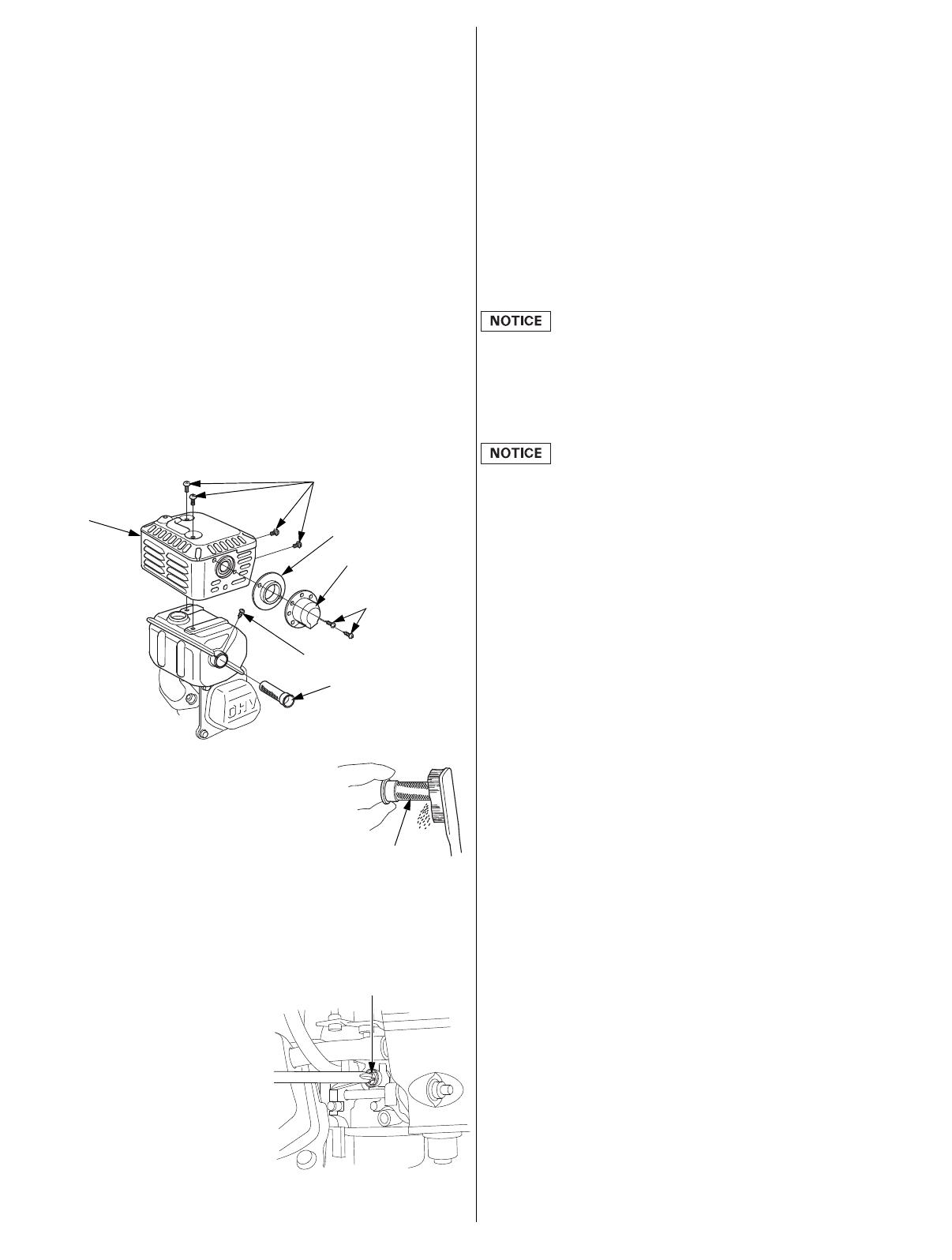
Spark Arrester Removal
1. Remove the air cleaner (see page 11).
2. Remove the two 4 mm screws from the exhaust deflector, and
then remove the deflector and muffler guide (applicable types).
3. Remove the four 5 mm screws from the muffler protector and
remove the muffler protector.
4. Remove the 4 mm screw from the spark arrester, and remove
the spark arrester from the muffler.
Spark Arrester Cleaning & Inspection
1. Use a brush to remove carbon
deposits from the spark arrester
screen. Be careful not to damage
the screen. Replace the spark
arrester if it has breaks or holes.
2. Install the spark arrester, muffler protector, exhaust deflector,
and muffler guide in the reverse order of removal.
3. Install the air cleaner (see page 11).
IDLE SPEED
Adjustment
1. Start the engine outdoors, and
allow it to warm up to
operating temperature.
2. Move the throttle lever to its
minimum position.
3. Turn the throttle stop screw to
obtain the standard idle speed.
Standard idle speed: 1,400 rpm
MUFFLER
PROTECTOR
5 mm SCREWS
4 mm SCREW
SPARK ARRESTER
EXHAUST
DEFLECTOR
MUFFLER GUIDE
4 mm SCREWS
SCREEN
THROTTLE STOP SCREW
+200
-150
HELPFUL TIPS & SUGGESTIONS
STORING YOUR ENGINE
Storage Preparation
Proper storage preparation is essential for keeping your engine
trouble-free and looking good. The following steps will help to keep
rust and corrosion from impairing your engine’s function and
appearance, and will make the engine easier to start when you use
it again.
Cleaning
If the engine has been running, allow it to cool for at least half an
hour before cleaning. Clean all exterior surfaces, touch up any
damaged paint, and coat other areas that may rust with a light film
of oil.
Using a garden hose or pressure washing equipment can force
water into the air cleaner or muffler opening. Water in the air
cleaner will soak the air filter, and water that passes through the air
filter or muffler can enter the cylinder, causing damage.
Fuel
Depending on the region where you operate your equipment, fuel
formulations may deteriorate and oxidize rapidly. Fuel deterioration
and oxidation can occur in as little as 30 days and may cause
damage to the carburetor and/or fuel system. Please check with
your servicing dealer for local storage recommendations.
Gasoline will oxidize and deteriorate in storage. Deteriorated
gasoline will cause hard starting, and it leaves gum deposits that
clog the fuel system. If the gasoline in your engine deteriorates
during storage, you may need to have the carburetor and other fuel
system components serviced or replaced.
The length of time that gasoline can be left in your fuel tank and
carburetor without causing functional problems will vary with such
factors as gasoline blend, your storage temperatures, and whether
the fuel tank is partially or completely filled. The air in a partially
filled fuel tank promotes fuel deterioration. Very warm storage
temperatures accelerate fuel deterioration. Fuel deterioration
problems may occur within a few months, or even less if the
gasoline was not fresh when you filled the fuel tank.
Fuel system damage or engine performance problems resulting from
neglected storage preparation are not covered under the
Distributor’s Limited Warranty.
You can extend fuel storage life by adding a gasoline stabilizer that
is formulated for that purpose, or you can avoid fuel deterioration
problems by draining the fuel tank and carburetor.
Adding a Gasoline Stabilizer to Extend Fuel Storage Life
When adding a gasoline stabilizer, fill the fuel tank with fresh
gasoline. If only partially filled, air in the tank will promote fuel
deterioration during storage. If you keep a container of gasoline for
refueling, be sure that it contains only fresh gasoline.
1. Add gasoline stabilizer following the manufacturer’s
instructions.
2. After adding a gasoline stabilizer, run the engine outdoors for 10
minutes to be sure that treated gasoline has replaced the
untreated gasoline in the carburetor.
3. Stop the engine.
32Z4HA00.fm 13 ページ 2012年7月11日 水曜日 午前10時3分
14 ENGLISH
Draining the Fuel Tank and Carburetor
1. Move the fuel valve lever to the OFF position (see page 6).
2. Place an approved gasoline container below the carburetor, and
use a funnel to avoid spilling fuel.
3. Remove the carburetor drain bolt and gasket. Remove the
sediment cup and O-ring, then move the fuel valve lever to the
ON position (see page 4).
4. After all the fuel has drained into the container, reinstall the
drain bolt, gasket, sediment cup and O-ring. Tighten the drain
bolt and sediment cup securely.
Engine Oil
1. Change the engine oil (see page 9).
2. Remove the spark plug (see page 12).
3. Pour a teaspoon 5–10 cm3 (5–10 cc) of clean engine oil into the
cylinder.
4. Pull the starter rope several times to distribute the oil in the
cylinder.
5. Reinstall the spark plug.
6. Pull the starter rope slowly until resistance is felt and the notch
on the starter pulley aligns with the hole at the top of the recoil
starter cover. This will close the valves so moisture cannot enter
the engine cylinder. Return the starter rope gently.
7. Electric starter type: Remove the battery and store it in a cool,
dry place. Recharge it once a month.
8. Cover the engine to keep out dust.
Gasoline is highly flammable and explosive, and you
can be burned or seriously injured when handling fuel.
Stop the engine and keep heat, sparks, and flame
away.
Handle fuel only outdoors.
Wipe up spills immediately.
ON
GASKET
CARBURETOR
DRAIN BOLT
FUEL VALVE
LEVER
O-RING
SEDIMENT
CUP
Align notch on pulley with
hole at top of cover.
Storage Precautions
If your engine will be stored with gasoline in the fuel tank and
carburetor, it is important to reduce the hazard of gasoline vapor
ignition. Select a well ventilated storage area away from any
appliance that operates with a flame, such as a furnace, water
heater, or clothes dryer. Also avoid any area with a
spark-producing electric motor, or where power tools are operated.
If possible, avoid storage areas with high humidity, because that
promotes rust and corrosion.
Keep the engine level in storage. Tilting can cause fuel or oil
leakage.
With the engine and exhaust system cool, cover the engine to keep
out dust. A hot engine and exhaust system can ignite or melt some
materials. Do not use sheet plastic as a dust cover.
A nonporous cover will trap moisture around the engine, promoting
rust and corrosion.
If equipped with a battery for electric starter types, recharge the
battery once a month while the engine is in storage.
This will help to extend the service life of the battery.
Removal from Storage
Check your engine as described in the BEFORE OPERATION
CHECKS section of this manual (see page 4).
If the fuel was drained during storage preparation, fill the tank with
fresh gasoline. If you keep a container of gasoline for refueling, be
sure it contains only fresh gasoline. Gasoline oxidizes and
deteriorates over time, causing hard starting.
If the cylinder was coated with oil during storage preparation, the
engine will smoke briefly at startup. This is normal.
TRANSPORTING
If the engine has been running, allow it to cool for at least 15
minutes before loading the engine-powered equipment on the
transport vehicle. A hot engine and exhaust system can burn you
and can ignite some materials.
Keep the engine level when transporting to reduce the possibility of
fuel leakage. Move the fuel valve lever to the OFF position (see page
6).
32Z4HA00.fm 14 ページ 2012年7月11日 水曜日 午前10時3分
ENGLISH 15
TAKING CARE OF UNEXPECTED PROBLEMS
ENGINE WILL
NOT START
Possible Cause Correction
1. Electric starting
(applicable types):
Check battery
and fuse.
Battery discharged. Recharge battery.
Fuse burnt out. Replace fuse
(p. 15).
2. Check control
positions.
Fuel valve OFF. Move lever to ON
position.
Choke open. Move lever to
CLOSED position
unless the engine is
warm.
Engine switch OFF. Turn engine switch
to ON position.
3. Check engine oil
level.
Engine oil level low
(Oil Alert models).
Fill with the
recommended oil to
the proper level
(p. 9).
4. Check fuel. Out of fuel. Refuel (p. 8).
Bad fuel; engine
stored without
treating or draining
gasoline, or refueled
with bad gasoline.
Drain fuel tank and
carburetor (p. 14).
Refuel with fresh
gasoline (p. 8).
5. Remove and
inspect spark
plug.
Spark plug faulty,
fouled, or improperly
gapped.
Gap or replace spark
plug (p. 12).
Spark plug wet with
fuel
(flooded engine).
Dry and reinstall
spark plug. Start
engine with throttle
lever in MAX.
position.
6. Take engine to an
authorized Honda
servicing dealer,
or refer to shop
manual.
Fuel filter restricted,
carburetor
malfunction, ignition
malfunction, valves
stuck, etc.
Replace or repair
faulty components
as necessary.
ENGINE LACKS
POWER
Possible Cause Correction
1. Check air filter. Filter element(s)
restricted.
Clean or replace
filter element(s)
(p. 11–12).
2. Check fuel. Bad fuel; engine
stored without
treating or draining
gasoline, or refueled
with bad gasoline.
Drain fuel tank and
carburetor (p. 14).
Refuel with fresh
gasoline (p. 8).
3. Take engine to an
authorized Honda
servicing dealer,
or refer to shop
manual.
Fuel filter restricted,
carburetor
malfunction, ignition
malfunction, valves
stuck, etc.
Replace or repair
faulty components
as necessary.
FUSE REPLACEMENT (applicable types)
The electric starter relay circuit and battery charging circuit are
protected by a fuse. If the fuse burns out, the electric starter will
not operate. The engine can be started manually if the fuse burns
out, but running the engine will not charge the battery.
1. Remove the 6×12 mm special screw from the rear cover of the
engine switch box, and remove the rear cover.
2. Remove the fuse cover, then pull out and inspect the fuse.
If the fuse is burnt out, discard the burnt-out fuse. Install a new
fuse with the same rating as the one that was removed, and
reinstall the cover.
If you have questions regarding the rating of the original fuse,
contact your Honda servicing dealer.
Never use a fuse with a rating greater than the one originally
equipped with the engine. Serious damage to the electrical
system or a fire could result.
3. Reinstall the rear cover. Install the 6×12 mm screw and tighten
it securely.
Frequent fuse failure usually indicates a short circuit or an overload
in the electrical system. If the fuse burns out frequently, take the
engine to a Honda servicing dealer for repair.
ENGINE SWITCH
REAR COVER
6×12 mm
SPECIAL SCREW
FUSE
COVER
FUSE
32Z4HA00.fm 15 ページ 2012年7月11日 水曜日 午前10時3分
16 ENGLISH
TECHNICAL INFORMATION
Serial Number Location
Record the engine serial
number, type and purchase
date in the spaces below. You
will need this information when
ordering parts and when
making technical or warranty
inquiries.
Engine serial number: __ __ __ __ — __ __ __ __ __ __ __
Engine type: ___ ___ ___ ___
Date Purchased: ______ / ______ / ______
Battery Connections for Electric Starter (applicable types)
Use a 12-volt battery with an ampere-hour rating of at least 18 Ah.
Be careful not to connect the battery in reverse polarity, as this will
short circuit the battery charging system. Always connect the
positive (+) battery cable to the battery terminal before connecting
the negative (–) battery cable, so your tools cannot cause a short
circuit if they touch a grounded part while tightening the positive
(+) battery cable end.
WARNING: Battery posts, terminals, and related accessories
contain lead and lead compounds. Wash hands after handling.
1. Connect the battery positive (+) cable to the starter solenoid
terminal as shown.
2. Connect the battery negative (–) cable to an engine mounting
bolt, frame bolt, or other good engine ground connection.
3. Connect the battery positive (+) cable to the battery positive
(+) terminal as shown.
4. Connect the battery negative (–) cable to the battery negative
(–) terminal as shown.
5. Coat the terminals and cable ends with grease.
A battery can explode if you do not follow the correct
procedure, seriously injuring anyone nearby.
Keep all sparks, open flames, and smoking materials
away from the battery.
SERIAL NUMBER &
ENGINE TYPE LOCATION
ELECTRIC
STARTER
(applicable
types)
STARTER
SOLENOID
POSITIVE (+) BATTERY CABLE
NEGATIVE (–)
BATTERY CABLE
Remote Control Linkage
The throttle and choke control levers are provided with holes for
optional cable attachment. The following illustrations show
installation examples for a solid wire cable and for a flexible, braided
wire cable. If using a flexible, braided wire cable, add a return spring
as shown.
It is necessary to loosen the throttle lever friction nut when
operating the throttle with a remote-mounted control.
REMOTE THROTTLE LINKAGE
REMOTE CHOKE LINKAGE
THROTTLE LEVER
FRICTION NUT
Flexible wire core
mounting
RETURN
SPRING
Solid wire core
mounting
WIRE
5 mm
CIRCLIP
4 mm SCREW
WIRE HOLDER
THROTTLE
LEVER
OPTIONAL
WIRE HOLDER
CHOKE LEVER
32Z4HA00.fm 16 ページ 2012年7月11日 水曜日 午前10時3分
ENGLISH 17
Carburetor Modifications for High Altitude Operation
At high altitude, the standard carburetor air-fuel mixture will be too
rich. Performance will decrease, and fuel consumption will increase.
A very rich mixture will also foul the spark plug and cause hard
starting. Operation at an altitude that differs from that at which this
engine was certified, for extended periods of time, may increase
emissions.
High altitude performance can be improved by specific
modifications to the carburetor. If you always operate your engine
at altitudes above 1,500 meters (5,000 feet), have your servicing
dealer perform this carburetor modification. This engine, when
operated at high altitude with the carburetor modifications for high
altitude use, will meet each emission standard throughout its useful
life.
Even with carburetor modification, engine horsepower will decrease
about 3.5% for each 300 meter (1,000 foot) increase in altitude.
The effect of altitude on horsepower will be greater than this if no
carburetor modification is made.
When the carburetor has been modified for high altitude operation,
the air-fuel mixture will be too lean for low altitude use. Operation
at altitudes below 1,500 meters (5,000 feet) with a modified
carburetor may cause the engine to overheat and result in serious
engine damage. For use at low altitudes, have your servicing dealer
return the carburetor to original factory specifications.
Emission Control System Information
Source of Emissions
The combustion process produces carbon monoxide, oxides of
nitrogen, and hydrocarbons. Control of hydrocarbons and oxides of
nitrogen is very important because, under certain conditions, they
react to form photochemical smog when subjected to sunlight.
Carbon monoxide does not react in the same way, but it is toxic.
Honda utilizes appropriate air/fuel ratios and other emissions control
systems to reduce the emissions of carbon monoxide, oxides of
nitrogen, and hydrocarbons.
Additionally, Honda fuel systems utilize components and control
technologies to reduce evaporative emissions.
The U.S., California Clean Air Act, and Environment Canada
EPA, California, and Canadian regulations require all manufacturers
to furnish written instructions describing the operation and
maintenance of emission control systems.
The following instructions and procedures must be followed in order
to keep the emissions from your Honda engine within the emission
standards.
Tampering and Altering
Tampering with or altering the emission control system may
increase emissions beyond the legal limit. Among those acts that
constitute tampering are:
Removal or alteration of any part of the intake, fuel, or exhaust
systems.
Altering or defeating the governor linkage or speed-adjusting
mechanism to cause the engine to operate outside its design
parameters.
Problems That May Affect Emissions
If you are aware of any of the following symptoms, have your
engine inspected and repaired by your servicing dealer.
Hard starting or stalling after starting.
Rough idle.
Misfiring or backfiring under load.
Afterburning (backfiring).
Black exhaust smoke or high fuel consumption.
Replacement Parts
The emission control systems on your Honda engine were designed,
built, and certified to conform with EPA, California and Canadian
emission regulations. We recommend the use of genuine Honda
parts whenever you have maintenance done.
These original-design replacement parts are manufactured to the
same standards as the original parts, so you can be confident of
their performance. The use of replacement parts that are not of the
original design and quality may impair the effectiveness of your
emission control system.
A manufacturer of an aftermarket part assumes the responsibility
that the part will not adversely affect emission performance. The
manufacturer or rebuilder of the part must certify that use of the
part will not result in a failure of the engine to comply with
emission regulations.
Maintenance
Follow the maintenance schedule on page 7. Remember that this
schedule is based on the assumption that your machine will be
used for its designed purpose. Sustained high-load or
high-temperature operation, or use in unusually wet or dusty
conditions, will require more frequent service.
32Z4HA00.fm 17 ページ 2012年7月11日 水曜日 午前10時3分
18 ENGLISH
Air Index
(Models certified for sale in California)
An Air Index Information label is applied to engines certified to an
emission durability time period in accordance with the requirements
of the California Air Resources Board.
The bar graph is intended to provide you, our customer, the ability
to compare the emissions performance of available engines. The
lower the Air Index, the less pollution.
The durability description is intended to provide you with
information relating to the engine’s emission durability period.
The descriptive term indicates the useful life period for the engine’s
emission control system. See your Emission Control System
Warranty for additional information.
Descriptive Term Applicable to Emissions Durability Period
Moderate 50 hours (0–80 cc, inclusive)
125 hours (greater than 80 cc)
Intermediate 125 hours (0–80 cc, inclusive)
250 hours (greater than 80 cc)
Extended 300 hours (0–80 cc, inclusive)
500 hours (greater than 80 cc)
1,000 hours (225 cc and greater)
Specifications
GX120 (PTO shaft type S, with fuel tank)
GX160 (PTO shaft type S, with fuel tank)
GX200 (PTO shaft type S, with fuel tank)
Length×Width×Height 297×346×329 mm
(11.7×13.6×13.0 in)
Dry mass [weight] 13.0 kg (28.7 lbs)
Engine type 4-stroke, overhead valve, single cylinder
Displacement
[Bore×Stroke] 118 cm3 (7.2 cu-in)
[60.0×42.0 mm (2.4×1.7 in)]
Engine oil capacity 0.56 L (0.59 US qt, 0.49 lmp qt)
Fuel tank capacity 2.0 L (0.53 US gal, 0.44 lmp gal)
Cooling system Forced air
Ignition system Transistorized magneto
PTO shaft rotation Counterclockwise
Length×Width×Height 304×362×346 mm
(12.0×14.3×13.6 in)
Dry mass [weight] 15.1 kg (33.3 lbs)
Engine type 4-stroke, overhead valve, single cylinder
Displacement
[Bore×Stroke] 163 cm3 (9.9 cu-in)
[68.0×45.0 mm (2.7×1.8 in)]
Engine oil capacity 0.58 L (0.61 US qt, 0.51 lmp qt)
Fuel tank capacity 3.1 L (0.82 US gal, 0.68 lmp gal)
Cooling system Forced air
Ignition system Transistorized magneto
PTO shaft rotation Counterclockwise
Length×Width×Height 313×376×346 mm
(12.3×14.8×13.6 in)
Dry mass [weight] 16.1 kg (35.5 lbs)
Engine type 4-stroke, overhead valve, single cylinder
Displacement
[Bore×Stroke] 196 cm3 (12.0 cu-in)
[68.0×54.0 mm (2.7×2.1 in)]
Engine oil capacity 0.60 L (0.63 US qt, 0.53 lmp qt)
Fuel tank capacity 3.1 L (0.82 US gal, 0.68 lmp gal)
Cooling system Forced air
Ignition system Transistorized magneto
PTO shaft rotation Counterclockwise
32Z4HA00.fm 18 ページ 2012年7月11日 水曜日 午前10時3分
ENGLISH 19
Tuneup Specifications GX120/160/200
Quick Reference Information
ITEM SPECIFICATION MAINTENANCE
Spark plug gap 0.7–0.8 mm
(0.028–0.031 in)
Refer to page: 12
Idle speed 1,400 rpm Refer to page: 13
Valve
clearance
(cold)
GX120
GX200
IN: 0.15±0.02 mm
EX: 0.20±0.02 mm
See your
authorized
Honda dealer
GX160 IN: 0.08±0.02 mm
EX: 0.10±0.02 mm
Other
specifications
No other adjustments needed.
Fuel Unleaded gasoline (Refer to page 8)
U.S. Pump octane rating 86 or higher
Except
U.S.
Research octane rating 91 or higher
Pump octane rating 86 or higher
Engine oil SAE 10W-30, API SJ or later, for general use.
Refer to page 8.
Reduction
case oil
Same oil as engine oil, see above (applicable
types).
Spark plug BPR6ES (NGK)
W20EPR-U (DENSO)
Maintenance Before each use:
Check engine oil level. Refer to page 9.
Check reduction case oil (applicable types).
Refer to page 9–10.
Check air filter. Refer to page 10.
First 20 hours:
Change engine oil. Refer to page 9.
Change reduction case oil (applicable types).
Refer to page 10.
Subsequent:
Refer to the maintenance schedule on page 7.
+200
-150
Wiring Diagrams
With Oil Alert and Electric Starter
(1) CONTROL BOX (8) OIL LEVEL SWITCH
(2) RECTIFIER (9) CHARGING COIL
(3) FUSE (10) IGNITION COIL
(4) CIRCUIT BREAKER (11) SPARK PLUG
(5) ENGINE SWITCH (12) STARTER MOTOR
(6) OIL ALERT UNIT (13) STARTER SOLENOID
(7) Type with Oil Alert unit (14) BATTERY (12 V)
Bl Black Br Brown
Y Yellow O Orange
Bu Blue Lb Light blue
G Green Lg Light green
RRed PPink
W White Gr Gray
With Oil Alert and Without Electric Starter
(14) (13) (11)
(12)
(10) (9) (8)
(7)
(6) (5)
(4)
(3)
(2)
(1)
OFF
ON
START
IG E BAT ST
oo
oo
(11)
(10)
(5)
(6)
(8)
IG E
OFF
ON
oo
32Z4HA00.fm 19 ページ 2012年7月11日 水曜日 午前10時3分
20 ENGLISH
CONSUMER INFORMATION
Warranty and Distributor/Dealer Locator Information
United States, Puerto Rico, and U.S. Virgin Islands:
Visit our website: www.honda-engines.com
Canada:
Call (888) 9HONDA9
or visit our website: www.honda.ca
For European Area:
Visit our website: http://www.honda-engines-eu.com
Australia:
Call (03) 9270 1348
or visit our website: www.hondampe.com.au
Customer Service Information
Servicing dealership personnel are trained professionals. They
should be able to answer any question you may have. If you
encounter a problem that your dealer does not solve to your
satisfaction, please discuss it with the dealership’s management.
The Service Manager, General Manager, or Owner can help. Almost
all problems are solved in this way.
United States, Puerto Rico, and U.S. Virgin Islands:
If you are dissatisfied with the decision made by the dealership’s
management, contact the Honda Regional Engine Distributor for
your area.
If you are still dissatisfied after speaking with the Regional Engine
Distributor, you may contact the Honda Office as shown.
All Other Areas:
If you are dissatisfied with the decision made by the dealership’s
management, contact the Honda Office as shown.
<Honda’s Office>
When you write or call, please provide this information:
Equipment manufacturer’s name and model number that the
engine is mounted on
Engine model, serial number, and type (see page 16)
Name of dealer who sold the engine to you
Name, address, and contact person of the dealer who services
your engine
Date of purchase
Your name, address and telephone number
A detailed description of the problem
United States, Puerto Rico, and U.S. Virgin Islands:
American Honda Motor Co., Inc.
Power Equipment Division
Customer Relations Office
4900 Marconi Drive
Alpharetta, GA 30005-8847
Or telephone: (770) 497-6400, 8:30 am - 7:00 pm ET
Canada:
Honda Canada, Inc.
180 Honda Blvd.
Markham, ON L6C 0H9
Telephone: (888) 9HONDA9 Toll free
(888) 946-6329
Facsimile: (877) 939-0909 Toll free
Australia:
Honda Australia Motorcycle and Power Equipment Pty. Ltd.
1954–1956 Hume Highway
Campbellfield Victoria 3061
Telephone: (03) 9270 1111
Facsimile: (03) 9270 1133
For European Area:
Honda Europe NV.
European Engine Center
http://www.honda-engines-eu.com
All Other Areas:
Please contact the Honda distributor in your area for assistance.
32Z4HA00.fm 20 ページ 2012年7月11日 水曜日 午前10時3分
  • Page 1 1
  • Page 2 2
  • Page 3 3
  • Page 4 4
  • Page 5 5
  • Page 6 6
  • Page 7 7
  • Page 8 8
  • Page 9 9
  • Page 10 10
  • Page 11 11
  • Page 12 12
  • Page 13 13
  • Page 14 14
  • Page 15 15
  • Page 16 16
  • Page 17 17
  • Page 18 18
  • Page 19 19
  • Page 20 20
  • Page 21 21
  • Page 22 22
  • Page 23 23
  • Page 24 24
  • Page 25 25
  • Page 26 26
  • Page 27 27
  • Page 28 28
  • Page 29 29
  • Page 30 30
  • Page 31 31
  • Page 32 32
  • Page 33 33
  • Page 34 34
  • Page 35 35
  • Page 36 36
  • Page 37 37
  • Page 38 38
  • Page 39 39
  • Page 40 40
  • Page 41 41
  • Page 42 42
  • Page 43 43
  • Page 44 44
  • Page 45 45
  • Page 46 46
  • Page 47 47
  • Page 48 48
  • Page 49 49
  • Page 50 50
  • Page 51 51
  • Page 52 52
  • Page 53 53
  • Page 54 54
  • Page 55 55
  • Page 56 56
  • Page 57 57
  • Page 58 58
  • Page 59 59
  • Page 60 60

Honda GX200UT2QX2 Owner's manual

Type
Owner's manual

Ask a question and I''ll find the answer in the document

Finding information in a document is now easier with AI