Page is loading ...

CHRONOMITE INSTANT-FLOW MICRO WATER HEATERS
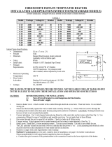
INSTALLATION AND OPERATION INSTRUCTIONS (STANDARD MODELS)
(Before installation, compare electrical needed for the model of heater selected)
TABLE 1
Instant-Flow Micro Specifications:
•Dimensions: 6 ¼ ” x 9 5/8 ” x 2 ¾ ”
• Weight: 5 lbs.
•Materials: Rugged cast aluminum alloy casing, Celcon waterways with nichrome parts
•Color: White (unless stainless steel housing)
•Pipe Fittings: Female ¼” NPT standard pipe thread
•Pressure Requirements: 25 PSI Minimum 150 PSI Maximum (300 PSI tested) No pressure relief valve needed
unless required by local codes.
•Maximum Operating Temp: 140°F
•Minimum Operating Flow Rate: .65 GPM
*Minimum Operating Flow Rate: 1.0gpm for Models
M-40-220/240, M-40/277 & M-50-220/240
•Listings: UL, HUD, IAPMO
THE MANUFACTURER OF THIS WATER HEATER WILL NOT BE LIABLE FOR ANY DAMAGES
DUE TO THE FAILURE TO FOLLOW THESE INSTALLATION AND OPERATION INSTRUCTIONS.
CAUTION: BEFORE BEGINNING THE INSTALLATION:
A) Turn off the circuit breaker to avoid dangerous electrical shocks.
B) Turn off the water supply.
1. Remove electrical access cover. Attach conduit to the conduit access hole. Then feed wires. Do not attach wiring.
2. Mount unit horizontally against the wall so the silver label reads correctly (See Fig. 1). Mount with four screws
through the flanges located on each corner using molly anchors or fasteners.
CAUTION: Heating elements may burn out if not mounted horizontally.
3. Connect plumbing. Use ¼” tapered national pipe thread at cold water inlet and hot water outlet (See Fig. 1). Use
compression fittings supplied for ease of installation. Do not apply heat to these fittings.
4. Run water through the unit to expel all air bubbles. Check for leaks at all fitting joints.
5. Connect wiring. Attach ground wire to center terminal and hot wires to outer terminals (See Fig. 3).
6. Replace electrical access cover. Turn on the circuit breaker. The unit is now ready for use.
7. Local plumbing and electrical codes must be followed in the installation of this water heater and it’s accessories.
8. Failure to comply with code requirements voids the warranty.
Model No. Wattage Voltage Breaker
Size
M-30 6240 208 30A
M-30 7200 220/240 30A
M-30 8310 277 30A
M-40 8320 208 40A
M-40 9600 220/240 40A
M-40 11080 277 40A
M-50 11520 220/240 50A
Downloaded from www.GadgetsGo.com, Authorized Chronomite Distributor

page 1
IMPORTANT NOTES: Air in the heater may cause the element to burn out. If the water lines are drained,
allowing air into the heater, be sure to follow the following start-up procedure:
1. Turn off electrical supply at circuit breaker.
2. Turn on water supply.
3. Expel all air from lines and heater.
4. Turn on electrical power supply at circuit breaker.
FIGURE 1 HEATER INSTALLATION
Faucet flow controls attached to the faucet allow the water heating system operate more effectively. For example, 2 GPM
flow controls recommended for faucets, assure that the flow rate will not exceed 2 GPM. However, less water can always
be used. Also, consumers can mix with cold water as with a conventional system (See Fig. 2, pg. 3 for Installation).
Item Part No. Names Qty Description
1. M-_ _ Chronomite Instant-Flow Micro 1 Models shown in Table 1
2. Electrical junction box
3. Electrical conduit ½” conduit, length as required
4. Electrical wire Wire size shown in Table 1
5. Dual outlet angle valve 1 ½” FPx7/16” comp.x3/8 comp., Brass
Craft P/N R2701R-RGH
6. Fitting (supplied) 2 3/8” comp x ¼”MP
7. Copper or flex tubing 1 3/8” OD, 5” long (keep short)
8. Copper or flex tubing 3/8” OD, length as required (keep short)
9. A-212 Faucet flow control (supplied) 1 dual thread 15/16” male thread
or and 55/64” female thread (See
Hot
Sin
k
Mounting
Flange
Cold
#1
#2
#3
Conduit
#5
#6
#7
#9
#10
#4
#8
Downloaded from www.GadgetsGo.com, Authorized Chronomite Distributor

Figure 2)
adapters if needed 3
Note:C=Copper Cup MP=Male Pipe FP=female Pipe STD=Thread Comp=Compression Fittings
page 2
OPERATION INSTRUCTIONS
Turn the hot water fixture to activate the flow switch. The flow switch activates at one gallon per minute (GPM) and
deactivates at .65 gallon per minute.
If you increase the flow rate of the water will become cooler. Cold water can always be mixed just as with a conventional
system if using a two handle faucet.
Once you decrease the flow rate to .65 GPM the unit will deactivate. It is not advisable to operate the heaters at the
.65 GPM.
>Periodically inspect the supply lines, connections and heater for any moisture, corrosion or other potential preventable
problems.
HOW INSTANT-FLOW MICRO WORKS
The cast alloy case houses a series of ingeniously designed coils that instantly heat water as it flows through the vessel. A
unique power switch automatically applies electrical current to the coils when hot water is being requested. The electrical
current is not applied when the water is not in use. The microprocessor is internally preset at the factory to maintain a
constant output temperature with varying flow rates.
OPTIONS/ FLOW CONTROLS
You may want to install the supplied flow control in your design. This high-quality control makes the water heating system
operate more effectively, as well as saving water. The supplied 2.0 GPM flow control assures that the flow rate will not
exceed 2 GPM. However, less water can always be used. Consumers can mix the cold water as with a conventional
system.
LOW FLOW RATE SYSTEM
For applications where a 0.5 GPM flow rate is desirable and / or where only 110 VAC is available, see our low flow rate
system outlined in Installation Sheet #927.
FLOW CONTROL MODELS
Model GPM Vandal Proof Models GPM
A-212 (Male/female) 2.0 A-200VR (Male) 2.0
Adapters A-210VR (Female) 2.0
FLOW CONTROL SPECIFICATIONS
Material: Chrome plated, brass housing.
Threading: MODEL A-212 has male (outside) threads for faucets
with 15/16” female threads and has female
(inside) threads for faucets with 55/64” male threads.
*Flow controls are adaptable to other thread configurations.
Please use one of the three adapters supplied if needed. FACTORY SET
Please call factory if adapter is needed and one of the supplied adapters doesn’t work.
FIGURE 2
FLOW CONTROL INSTALLATION (See Parts List #9, #10) Choose from the following:
104 ºF
110 ºF see *** below
120 ºF see *** below
*Other Temperature Settings are
available upon request up to
140 ºF

** Temperature Settings are not
Field adjustable
*** 110 ºF / 120 ºF Temperature
settings are recommended with
cold water mixing faucets
page 3
TEMPERATURE INCREASE ABOVE INCOMING WATER TEMPERATURE
MODEL VAC 0.65GPM 1.0 GPM 1.5 GPM 2.0GPM
M-30 208 66°F 42°F 28°F 21°F
M-30 240 64°F 49°F 33°F 25°F
M-30 277 64°F 57°F 38°F 28°F
M-40 208 87°F 57°F 38°F 29°F
M-40 240 xxxx 65ºF 44°F 33°F
M-40 277 xxxx 75°F 50°F 38°F
M-50 240 xxxx 79ºF 55°F 41°F
Microprocessor limits temperature increase according to
the factory set temperature
FIGURE 3 Wiring Connection
TROUBLESHOOTING GUIDE
Your Instant-Flow Micro water heater has no internal user serviceable parts and should be returned to the factory for repair
or replacement. Please contact factory for return authorization. If after following the Installation Instructions, your
Instant-Flow Micro does not heat water in accordance with this literature, please check the following:
1. Low Power – Verify your voltage by using a voltage meter. You should obtain your reading off the two outside
terminals located on the heater. Compare this reading against the voltage specified in the
Installation Instructions. The center terminal is always the earth ground.
2. Low Voltage – The percentage of reduction in voltage will result in a like reduction in temperature increase.
3. Check Low Amperage Draw – Check amperage draw using an Amperage Probe. Please compare your
results with the Installation Instruction (Table 1) to determine if the heater is operating correctly.
4. Length of Pipe - Length of pipe run will affect the temperature increase. The heater should be mounted no
more the 12-18 inches from the point of use.
5. Check shut – off valve – Check shut-off valve and make sure valve is open 100% to allow full water pressure
to the heater.
6. Check Flow Rate – Controlling flow rate is essential to insure proper temperature increase. Check your flow
rate to insure proper operation of the heater. Standard Flow Rate Models require 1.0 GPM to activate.
7. Installation – Heater must be installed in a horizontal position. The silver label will then be located in the upper
left corner as you face the heater.
8. Water Supply – Cold water supply to only feed Instant-Flow Micro cold water inlet.
9. Freezing – Instant-Flow Micro heaters must be drained and stored if in a location subject to freezing.
Disconnect the inlet/outlet compression fittings and blow air through one side of the heater to assist draining.
Failure to completely remove water from the unit will result in freezing and cracking.
10. Problems? – Call our toll-free hotline 800/447-4962 or 626-937-4270.
EXCLUSIVE 12-MONTH WARRANTY
Your Instant-Flow Micro water heater has been engineered and built to the highest quality standards and is backed by
a full, factory warranty. Every Instant-Flow Micro water heater is guaranteed to be free from defects in material and
workmanship for a period of one (1) year from the date of purchase. The above warranty applies to original purchaser
if unit is installed to Chronomite Laboratories, Inc.’s Installation Instructions. Chronomite Laboratories, Inc. will repair
or exchange parts at the factory at no cost. This warranty is limited to repairing or replacing said products which
prove to be defective upon factory inspection, F.O.B. City of Industry, California.

/