Page is loading ...

INSTRUCTION MANUAL
C-BOX V1.6
Smart Processing Interface
For MS-90
C-Box Modbus 485

EKO INSTRUMENTS EUROPE B.V. C-BOX Instruction Manual
Pg. 1
1. Index
1. Index 1
2. Important User Information 2
2-1. Contact Information 2
2-2. Warranty and Liability 2
2-3. About Instruction Manual 3
2-4. Environment 3
2-5. CE Declaration 4
3. Safety Information 5
3-1. WARNING/CAUTION 5
4. Introduction 6
4-1. Package Contents 6
5. Getting Started 7
5-1. Parts Name 7
5-2. System Overview 7
5-3. Installation 8
5-4. Settings 8
5-5. Operating 10
5-6. Irradiance measurements 10
6. Modbus communication 12
6-1. Communication 12
6-2. Registers 13
6-3. Software 14
7. Specification 16
7-1. Main Unit 16
7-2. Dimensions 17
Appendix 18
Appendix -A.
Wiring table C-Box 18

EKO INSTRUMENTS EUROPE B.V. C-BOX Instruction Manual
Pg. 2
2. Important User Information
Thank you for using EKO Products
Make sure to read this instruction manual thoroughly and to understand the contents before starting to operate the
instrument. Keep this manual at safe and handy place for whenever it is needed.
For any questions, please contact us at one of the EKO offices given below:
2-1. Contact Information
EKO INSTRUMENTS CO., LTD.
Asia, Oceania Region
www.eko-asia.com
info@eko.co.jp
EKO INSTRUMENTS Co., Ltd.
1-21-8 Hatagaya, Shibuya-ku
Toky o , 1 51 -0072 Japan
Tel : +81 (3) 3469-6713
Fax: +81 (3) 3469-6719
Europe, Middle East, Africa, South America Region
www.eko-eu.com
info@eko-eu.com
EKO INSTRUMENTS Europe B.V.
Lulofsstraat 55, Unit 28,
2521 AL, Den Haag, The Netherlands
Tel : +31 (0)70 3050117
Fax: +31 (0)70 3840607
North America Region
www.eko-usa.com
info@eko-usa.com
EKO INSTRUMENTS USA Inc.
95 South Market Street, Suite 300
San Jose, CA 95113 USA
Tel : +1 408-977-7751
Fax: +1 408-977-7741
2-2. Warranty and Liability
For warranty terms and conditions, contact EKO or your distributor for further details.
EKO guarantees that the product delivered to customer has been verified, checked and tested to ensure that
the product meets the appropriate specifications. The product warranty is valid only if the product has been
installed and used according to the directives provided in this instruction manual.
In case of any manufacturing defect, the product will be repaired or replaced under warranty. However, the
warranty does not apply if:
Ø Any modification or repair was done by any person or organization other than EKO service personnel.
Ø The damage or defect is caused by not respecting the instructions of use as given on the product
brochure or the instruction manual.

EKO INSTRUMENTS EUROPE B.V. C-BOX Instruction Manual
Pg. 3
2-3. About Instruction Manual
Copy Rights Reserved by EKO Instruments Europe B.V. Making copies of whole or parts of this document
without permission from EKO is prohibited.
This manual was issued: 2021/01/04
Version Number: 1.6.4
2-4. Environment
1. WEEE Directive 2002/96/EC
This product is subjected to WEEE Directive 2002/96/EC and should not be mixed with general household
waste. For proper treatment, recovery and recycling, please take this product(s) to a designated recycle
collection point.
Disposing of this product correctly will help save valuable resources and prevent any potential negative effects
on human health and the environment, which could otherwise arise from inappropriate waste handling.
2. RoHS Directive 2002/95/EC
EKO Instruments has completed a comprehensive evaluation of its product range to ensure compliance with
RoHS Directive 2002/95/EC regarding maximum concentration values for substances. As a result all products
are manufactured using raw materials that do not contain any of the restricted substances referred to in the
RoHS Directive 2002/95/EC at concentration levels in excess of those permitted under the RoHS Directive
2002/95/EC, or up to levels allowed in excess of these concentrations by the Annex to the RoHS Directive
2002/95/EC.

EKO INSTRUMENTS EUROPE B.V. C-BOX Instruction Manual
Pg. 4
2-5. CE Declaration
DECLARATION OF CONFORMITY
We: EKO Instruments Europe B.V.
Lulofsstraat 55, U 28, Den Haag
2521 AL Den Haag
The Netherlands
Declare under our sole responsibility that the product:
Product Name : Control box for the MS-90 DNI sensor
Model No. : C-BOX
To which this declaration relates is in conformity with the following
harmonized standards of other normative documents:
Harmonized standards:
EN 61326-1:2006 Class A (Emission)
EN 61326-1:2006 (Immunity)
Following the provisions of the directive:
EMC-directive : 89/336/EEC
Amendment to the above directive : 93/68/EEC
Date : 01-02-2020
Position of Authorized Signatory : Technical Director
Name of Authorized Signatory : C.H. Hoogendijk

EKO INSTRUMENTS EUROPE B.V. C-BOX Instruction Manual
Pg. 5
3. Safety Information
EKO Products are designed and manufactured with consideration for safety; however, please make
sure to read and understand this instruction manual thoroughly to be able to operate the instrument
safely in the correct manner.
WARNING
CAUTION
Attention to user; pay attention to the instructions given on the
instruction manual with this sign.
3-1. WARNING/CAUTION
1. Installation
Ø Do not install C-BOX in a place, which it may get under water.
Ø Make sure the instruments are installed in a location where they are easily accessible for maintenance,
or it may lead to unexpected accidents and injury.
Ø Although this product is designed to meet EMC Directive compliance requirements, it may not fully satisfy
its primary specification/performance when using this product near following locations where strong
electromagnetic wave is generated. Please pay attention to the installation environment.
Outdoor: High voltage power line, power receiver/distribution facility, etc.
Indoor: Large-size chiller, large rotation device, microwave, etc.
2. Power Supply
Ø Always make sure to check the power supply voltage and type (AC/DC) before connecting and powering
ON the instruments.
Ø Use with fuse 0.5A connected in series on the power supply cable. Depending on the power supply
connected, large current may flow when the internal malfunction occurs, and may lead to generating heat
and fire.
3. Instruction Manual
Ø In this instruction manual contains basic and important operation information for the use of the C-BOX
for the MS-90 DNI sensor and MS-90 plus+ system.
Ø Read this instruction manual and understand the contents well before operating C-BOX.
Ø Also, keep this instruction manual in handy location in case you need it.

EKO INSTRUMENTS EUROPE B.V. C-BOX Instruction Manual
Pg. 6
4. Introduction
The C-BOX smart processing interface provides different functions for sensor control and data processing of
different EKO sensors. In combination with the MS-90 DNI sensor, the pulsed output can be converted into a
Modbus 485 RTU signal.
The C-Box Modbus 485 has a built in GPS receiver and is used as part of the MS-90 Plus+ sensor system. By
using this device, the MS-90 analogue output pulse is converted to digital. With an additional MS-80S or MS-80M
Smart pyranometer a turnkey system can be configured to measure DNI, GHI and DHI over Modbus.
With Modbus 485 communication, it is possible to connect with PV monitoring devices or datalogger, which have a
RS-485 serial interface and provide MODBUS serial communication.
The signal converter is integrated in an IP65 enclosure for outdoor installation. The settings for the measurements
and communication can be changed by using the EKO C-Box setup software.
4-1. Package Contents
Check the package contents first; if any missing item or damage is noticed, please contact EKO immediately.
Tabl e 4-1 Package Contents
Standard Items
Qty.
Remarks
C-BOX Main Unit
1
C-BOX-Modbus 485 with GPS
Cable
1
Standard Length: 10m for communication and power supply
Quick Start Guide
1
Contains Factory settings
MS-90 DNI Sensor, 1.5m cable
1
Optional item (Order with MS-90)
MS-80S GHI Sensor, 1.5m cable
1
Optional item (Order with MS-80S)

EKO INSTRUMENTS EUROPE B.V. C-BOX Instruction Manual
Pg. 7
5. Getting Started
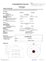
5-1. Parts Name
Each part name and its main functions are described below.
Figure 5-1-1. C-BOX Modbus 485 and Parts Name
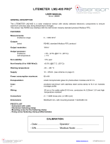
5-2. System Overview
The C-BOX Smart Processing Interface is used to build a sensor system to measure multiple irradiance
components. Below figure describes the system overview of C-BOX.
Figure 5-2-1. C-BOX system (sensors MS-90 and 80S are optional)
Output
Connector
MS-90 DNI Sensor
Input Connector
MS-80S Pyranometer
Input Connector
Air-vent
GPS Receiver

EKO INSTRUMENTS EUROPE B.V. C-BOX Instruction Manual
Pg. 8
5-3. Installation
The ideal mounting position is a place without any obstructions such as buildings, trees, and mountains,
however it might be difficult to find such location. As a general rule the sensors should have a clear horizon
above 5°. The setup location should be easily accessible for periodic maintenance of glass dome cleaning,
desiccant replacement, etc. Avoid surrounding towers, poles, walls or billboards with bright colors that can
reflect solar radiation onto the sensors.
For is installation of the sensors MS-90 DNI sensor and MS-80S pyranometer check out the online manuals
at EKO-EU.com.
5-4. Settings
1. Wiring
Connect all cables to the sensors and data acquisition system.
1. Connect the C-BOX to data logger via Modbus 485 RTU
2. Connect the Main Unit power supply
3. Connect the MS-90 DNI sensor signal cable to the sensor and C-Box
4. Connect the MS-80S Pyranometer signal cable to the sensor and C-Box
1. Output
Connector
3. MS-90 DNI Sensor
Input Connector
4. MS-80S Pyranometer
Input Connector
Air-vent
GPS Receiver

EKO INSTRUMENTS EUROPE B.V. C-BOX Instruction Manual
Pg. 9
2. Connections
To e xt en d t h e c a b l e l i f et ime, p re ve nt t ha t t h e c abl e s a r e n o t d i r ec tly e x po se d t o di r ect su n l i g h t or ra i n /w ind.
Cables can be placed in a cable conduit. Cable vibrations will potentially cause noise in the output signal.
Fasten the cable so that the cable does not swing or move by wind blowing. Exposure of the signal cable
to excessive electromagnetic emissions can cause noise in the output signal as well. Therefore the cable
should be lined at a safe distance from a potential source generating EMC noise, such as an AC power
supply, high voltage lines or telecom antenna.
Input MS-80S and MS-90
Tabl e 5-4-1. Internal connections MS-80S / 90 to C-BOX
Ter m i n al s
Function
1. Shield
Not used
2. Shield
Not used
3. 0V
MS-80S (White)
4. 12 VDC Out
MS-80S (Brown)
5. Modbus B
MS-80S (Black)
6. Modbus A
MS-80S (Blue)
7. Modbus GND
MS-80S (Grey)
8. Reserved
Not used
9. MS-80 (+) Analog
Disabled
10 MS-80 (-) Analog
Disabled
11. MS-90 DNI (+)
MS-90 (Brown)
12. MS-90 DNI (-)
MS-90 (White)
13. 0V
Not used
14. 0V
Not used
15. 12VDC Out MS-90
MS-90 (Blue)
16. 0VDC Out MS-90
MS-90 (Black)
Output Modbus 485 RTU
Tabl e 5-4-2. Connections C-BOX-Modbus 485 (Output)
5 Pin connector / wire Color
Function
1. Brown
12V Supply voltage
2. White
Supply voltage ground
3. Blue
Modbus (+) / A (RTU)
4. Black
Modbus (-) / B (RTU)
5. Grey
NC
C-BOX can connect to a system that communicates with Modbus 485 RTU. Connection of C-BOX to the RS-
485 communication network is shown below. The Master represents the data-logging device [such as PC],
and the slaves represent devices such as the C-BOX. Connect the + and –for the master to [A] and [B]. Also
at the end of the network, connect a 120Ω termination resistor.

EKO INSTRUMENTS EUROPE B.V. C-BOX Instruction Manual
Pg. 10
Figure 5-4-3. Connections of C-BOX in a Modbus 485 network
5-5. Operating
The Modbus operating mode is factory preset and can only be changed when operated in Modbus mode and
connected to a PC. When powering the C-BOX it will always start up in Modbus mode. After 30s it will change
to analog mode when set to analog mode. The analog mode and feature are not described in this manual.
5-6. Irradiance measurements
After powering the C-BOX all connected sensors automatically start measuring. For the MS-90 DNI
sensor, the mirror will start to rotate and the detector voltage output will build up due to internal charging
of a capacitor. This voltage will slowly decay to 0 if the irradiance conditions are 0 W/m2 after
approximately 1 minute.
Figure 5-6-1. C-BOX analog output signal
The DNI measurements are taken every 15 seconds based on the rotation speed of the mirror. Global
Irradiance (GHI) measurements are measured every 1 second.
For a system configured with MS-90 DNI and MS-80S pyranometer and operated in Modbus mode the three
irradiance components (DNI, GHI, DHI) will be measured.
The pyranometer (GHI) signal is converted into irradiance based on the sensitivity figure which is factory preset.
Hence the diffuse irradiance (DHI) is calculated based on the DNI and GHI.

EKO INSTRUMENTS EUROPE B.V. C-BOX Instruction Manual
Pg. 11
Irr DHI = Irr GHI - (Irr DNI • Cos ∂)
Irr DHI = Calculated diffuse horizontal irradiance [W/m2]
Irr GHI = Global Horizontal Irradiance [W/m2]
Irr DNI = Direct Normal Irradiance [W/m2]
Cos ∂ = Solar zenith angle (º)
For DNI values below 120 W/m2 the diffuse irradiance (DHI) is equal to the global irradiance GHI. The
second term (DNI) is set to zero.

EKO INSTRUMENTS EUROPE B.V. C-BOX Instruction Manual
Pg. 12
6. Modbus communication
6-1. Communication
Tabl e 6-1. C-BOX communication settings
C-Box
Function
Communication standard
RS-485
Protocol
Modbus Slave RTU
Communication speed
9600 Default
Data length
8bits
Node address
1 Default / can be changed with EKO software
Stop bit
1
Parity bit
None
Tabl e 6-2. MS-80S communication settings
MS-80S
Function
Communication standard
RS-485
Protocol
Modbus Slave RTU
Communication speed
19200
Data length
8bits
Node address
Last 2 digits of serial number (100 in case ending at 00)
Parity bit
Even
Tabl e 6-3. MS-80M communication settings
MS-80M
Function
Communication standard
RS-485
Protocol
Modbus Slave RTU
Communication speed
9600
Data length
8bits
Node address
1 Default
Parity bit
None

EKO INSTRUMENTS EUROPE B.V. C-BOX Instruction Manual
Pg. 13
6-2. Registers
Tabl e 6-2. C-BOX communication registers
Address
Label
Format
Description
0
MB_FW_VERSION
16 bit WORD
Firmware version
1
MB_SERIAL
16 bit WORD
Serial number
2
MB_SENSOR_MODEL
16 bit WORD
Sensor model
3
MB_BOARD_TEMPERATURE
16 bit WORD
PCB Temperature * 10
4
MB_MSX0
FLOAT
MS80S or M Global irradiance
6
MB_DNI
FLOAT
DNI
10
MB_NTC
FLOAT
MS80 Temperature
12
MB_DIFF
FLOAT
Diffuse
14
MB_TIMESTAMP
32 bit
Timestamp from GPS
18
MB_GPS_SATS
16 bit WORD
Amount of visible GPS satellites
22
MB_CF0
FLOAT
MS-80S or M calibration value
32
MB_CF5
FLOAT
MS-90 calibration value
34
MB_LAT
FLOAT
Latitude
36
MB_LON
FLOAT
Longitude
40
MB_ELEVATION
FLOAT
Sun elevation
42
MB_AZIMUTH
FLOAT
Sun azimuth

EKO INSTRUMENTS EUROPE B.V. C-BOX Instruction Manual
Pg. 14
6-3. Software
The C-Box configuration software can be downloaded from the EKO-EU website (MS-90+ plus product page).
Different measurement parameters can be displayed to verify the output parameters of the system. Sensor
and communication settings can be made to setup the system. For connection to a PC an optional USB to
485-communication cable is required.
Communication
The C-box communication is through Modbus 485 RTU.
C-Box communication setting (Default)
RS-485 : Modbus RTU
Baud-rate : 9600
Node address : 1
Parity : None
Stop bit : 1
Tabl e 6-3.1 Communications
Important Note: Any commercial USB / RS-485 communication can be used.
Data
When the GPS signal is available the latitude, Longitude and time information will be displayed. The solar
Elevation and Azimuth position are calculated based on the GPS data. When the DNI sensor and MS-80S
pyranometer is connected the GHI and DHI will be shown.
Tabl e 6-3.1 Data

EKO INSTRUMENTS EUROPE B.V. C-BOX Instruction Manual
Pg. 15
Settings
The setting menu can be used to change the sensitivity figure of the MS-90
DNI sensor. When the MS-90+ plus system is provided as a turn-key system,
all sensor setting (MS-90, MS-80S) are made.
MS-80S node address is last 2 digits of MS-80S serial number.
Tabl e 6-3.2 Settings

EKO INSTRUMENTS EUROPE B.V. C-BOX Instruction Manual
Pg. 16
7. Specification
7-1. Main Unit
Tabl e 8-1. C-Box Specification
Characteristics
Details
Input Signals
EKO MS-90 DNI sensor
Analog pulse 0 to 2V
EKO MS-80S/M Pyranometer
Modbus 485 RTU
Communication Method
RS-485 (Modbus RTU)
Operating Temperature Range
-40 to +80℃
Power Supply
12VDC (Note: Supply voltage critical for MS-90)
Average Power Consumption
0.5W
Dimensions (L / W / H)
125 x 60 x 80 mm
Weight (kg)
0.5
Ingress protection
IP 65
Tabl e 8-2. C-Box MS-90 Plus+ system Specifications
Characteristics
Details
Input parameters
EKO MS-90 DNI sensor
DNI
EKO MS-80S/M Pyranometer
GHI
Output parameters
DNI / GHI / DHI (Meta data T, RH, Tilt, Long / Lat position, Solar
Position, Time)
Sampling
1s (15s DNI)
Irradiance range DNI (Measured)
0 – 1600 W/m2
Irradiance range GHI (Measured)
0 – 1600W/m2
Irradiance range DHI (Calculated)
0 – 500 W/m2 (DHI = GHI when DNI < 120 W/m2)

EKO INSTRUMENTS EUROPE B.V. C-BOX Instruction Manual
Pg. 17
7-2. Dimensions
https://www.rose-systemtechnik.com/pim/assets/M01081306.pdf

EKO INSTRUMENTS EUROPE B.V. C-BOX Instruction Manual
Pg. 18
Appendix
Appendix -A. Wiring table C-Box
Tabl e ap pe nd i x Wiring table
Ter m i n al s
Function
1. Shield
Not connected
2. Shield
Not connected
3. 0V
MS-80S (White)
4. 12 VDC Out
MS-80S (Brown)
5. Modbus B
MS-80S (Black)
6. Modbus A
MS-80S (Blue)
7. Modbus GND
MS-80S (Grey)
8. Reserved
No used
9. MS-80 (+) Analog
Disabled
10 MS-80 (-) Analog
Disabled
11. MS-90 DNI (+)
MS-90 (Brown)
12. MS-90 DNI (-)
MS-90 (White)
13. 0V
No used
14. 0V
No used
15. 12VDC Out MS-90
MS-90 (Blue)
16. 0VDC Out MS-90
MS-90 (Black)

EKO Asia, Oceania
1-21-8 Hatagaya,
Shibuya-ku, Tokyo
151-0072 Japan
P. +81.3.3469.6711
F. +81.3.3469.6719
info@eko-asia.com
www.eko.co.jp
EKO North America
95 South Market Street,
Suite 300, San Jose,
CA 95113, USA
P. +1-408-977-7751
F. +1-408-977-7741
info@eko-usa.com
www.eko-usa.com
EKO Europe,
Middle East, Africa,
South America
Lulofsstraat 55, Unit 28,
2521 AL, Den Haag,
The Netherlands
P. +31 (0)70 3050117
F. +31 (0)70 3840607
info@eko-eu.com
www.eko-eu.com
/