Omegon 90/1000 EQ-2 User manual
- Category
- Telescopes
- Type
- User manual


Reproduction of part or all of the contents of this document in any form is expressly prohibited other than for individual use only. All text, images and labels are property of Nimax Gmbh.
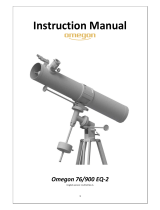
The Omegon® 90/1000 EQ-2
Congratulations on the purchase of the new Omegon® 90/1000 EQ-2. This telescope will give you
hours of fun, with its all optical glass achromatic lens it is the ideal companion to start in the world of
amateur astronomy. With this telescope you will be able to see the craters on the Moon, star
clusters, the Jupiter disc features and its Galilean moons and the rings of Saturn.
1. Included parts.
We have included several accessories
that will make the use of the
telescope easier and fun, please take a
look at the list of the parts so you can
identify them in the future.
1. & 2. Two eyepieces 1.25” (31.75mm); a
Plössl 25mm and a Plössl 6.3mm eyepiece;
3. 1.25” Diagonal Mirror;
4. Red-dot finderscope;
5. 2x magnification Barlow Lens.
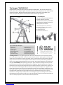
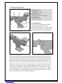
Figure 1. Mount parts description.
1- Dew-shield; 8- Latitude/alt. adjustment;
2- Optical tube; 9- Accessory tray;
3- Camera thread; 10- Leg fixing knob;
4- Tube ring; 11- Counterweight;
5- Red-dot finderscope; 12- Counterweight-shaft;
6- Focuser wheel; 13- Right Ascension handle;
7- Declination handle; 14- Declination locking knob;
2. Getting Started. It is very simple to get started. Here is how the telescope works. The telescope should
point to the object being observed. The front lens (inside the dew-shield #1 - figure 1) gathers the object’s light
and directs it to the eyepiece (on the focuser side #6 - figure 1). Rotate the focuser knob to obtain a focused
image. At the focuser one can use the supplied accessories. Different accessory combinations give different
results, such as different image magnifications or correct image. All this will be explained in more detail on the
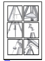
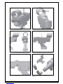
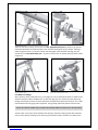
next pages. 3. Assembly. Start by setting up the tripod – figure 2. Open the tripod legs as shown place the
tripod accessory tray and use the three thumbscrews to fix it (figure 3). Adjust the legs extension – figure 4.
Extend them and fix using the three fixing knobs. Place the equatorial head on top of the tripod - Figure 5, and
fix it. Next thread the counterweight shaft by threading it to the Right Ascension (R.A.) axis – figure 6. Don’t
forget to thread the foot-saver (screw at end of shaft) after sliding-in the counterweight. Install both R.A. and
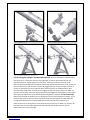
Dec. handles – figure 7. Place the optical tube by on the mount – figure 8 – and thread both ring screws. Install
the diagonal and eyepiece (don’t forget to tighten the focuser and finderscope fixing screws – figure 9).
Release the R.A. locking knob (not shown) slide the counterweight along the counterweight shaft to balance
the telescope then do the same for the Dec. axis – figure 11. Balancing is important so that the mount does not
wear out. Telescope operation is also easier with a balanced optical tube.
Figure 1. Parts list.

Reproduction of part or all of the contents of this document in any form is expressly prohibited other than for individual use only. All text, images and labels are property of Nimax Gmbh.
Figure 2. Tripod assembly.
Figure 3. Tray placement.
Figure 4. Adjust tripod’s extension.
Figure 5. Place the equatorial mount and fix it.
Figure 6. Thread the counterweight shaft.
Figure 7. Place the two R.A. and Dec. handles and fix it.

Reproduction of part or all of the contents of this document in any form is expressly prohibited other than for individual use only. All text, images and labels are property of Nimax Gmbh.
4. Start using your Omegon® 90/1000 EQ-2 telescope. Point the telescope to a distant object
during the day. It is important to do this during daylight, so that you get familiarized with the
telescope operation. A good target is a church tower, a chimney or a distant mountain peak.
Make an eyepiece and diagonal are installed and securely fixed. Rotate the focuser knob, so that the
focuser tube moves in and out. Do this slowly. We suggest that you start by racking the focuser all
the way in and slowly move it out. With the PLössl 25mm eyepiece you should be able to get a
focused (sharp) image easily. For night use we suggest starting with an easy object. The Moon is a
big object easy to point at and train telescope pointing. We suggest to use the Moon as a first target
before going to explore other more difficult objects like galaxies or nebulae. 5. The Finderscope.
Before we mentioned the finderscope as a valuable tool to point the telescope at an object. To use
the telescope properly, the telescope and the finderscope must be aligned. The image obtained
through the finderscope has a much broader field of view than that of the telescope. The
finderscope acts as an aiming device to the telescope. Even to point to the Moon it is necessary for
the finderscope to be accurately aligned with the telescope. Please take a look on how the
finderscope works in the next pages.
Figure 8. Tube placement.
Figure 9. Install the supplied accessories.
Figure 10. Balance the telescope tube R.A. axis.
Figure 11. Balance the telescope tube Dec. axis.

Reproduction of part or all of the contents of this document in any form is expressly prohibited other than for individual use only. All text, images and labels are property of Nimax Gmbh.
5.1. Knowing your finderscope.
5.2. Getting Started.
The finderscope is powered by a coin shaped
battery CR2032 (supplied). For battery
protection a plastic protection is placed between
the battery and the battery contact. Remove the
plastic protection by securing the finderscope
with one hand and then pulling firmly the outstanding plastic tip (figure 2). The plastic protection
should be completely removed and discarded. Turn power on by rotating the potentiometer to its
ON position as shown in figure 3 (you will hear a click when ON), rotate all the way to get maximum
power. When powered, the red-dot point on the red-dot case (#1 – figure1) lights (figure 4 and
figure 5). A small red point is projected on the optical window (#3 – figure 1). This red point, when
aligned with the telescope, allows precise pointing to objects. To precise align the finderscope with
the telescope both the altitude and azimuth (#8 and #4 figure 1) adjustment knobs need to be
adjusted (figure 6 and figure 7) – please see detail instructions on how to align in page 3. To power
off the finderscope just turn the potentiometer counter-clockwise until you hear a click – red-dot
dims until off (figure 8). Place the finderscope’s bracket in the telescope’s finderbase and tighten it
securely. Use a low power eyepiece to align the finderscope.
Finderscope main features
1- Red-dot case;
2- Potentiometer ON/OFF switch;
3- Optical window;
4- Azimuth adjusment knob;
5- Battery compartment (1x battery CR2032);
6- Base fixing screws;
7- Finderscope bracket;
8- Altitude adjustment knob.
Figure 12. Finderscope main features.
Figure 13. Remove plastic protection.
Figure 14. Turn power ON by rotating potentiometer.

Reproduction of part or all of the contents of this document in any form is expressly prohibited other than for individual use only. All text, images and labels are property of Nimax Gmbh.
Figure 15. Red-dot lights when ON.
Figure 16. A red-dot is projected on the optical window.
Figure 17. Turn azimuth adjustment knob to align finder.
Figure 18. Turn altitude adjustment knob to align finder.
Figure 19. Turn potentiometer OFF.
Figure 20. Insert finderscope and eyepiece in the
telescope.

Reproduction of part or all of the contents of this document in any form is expressly prohibited other than for individual use only. All text, images and labels are property of Nimax Gmbh.
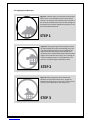
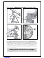
5.3. Aligning the Finderscope
Figure 21. A distant object is centered at the telescope’s
field of view. In this example we have a house with a
chimney. The chimney is the reference point to place at
the center of the field of view. We first look through the
telescope with the lowest magnification possible, so we
have the widest field of view.
STEP 1
Figure 22. Looking through the finderscope (it should
be powered ON) we see the same building ,but in this
case the red dot and chimney are not centered. We
adjust the finderscope using the two altitude and
azimuth knobs so that the finderscope red point moves
slightly until it matches the chimney. This is enough to
correct the objects position in the finderscope. Trial
and error is required to get a satisfactory result.
STEP 2
Figure 23. After playing with the two findercope
thumbscrews and some trial and error, we get the
finderscope red dot close to the center (in this case the
chimney). The finderscope is now ready to use!
STEP 3

Reproduction of part or all of the contents of this document in any form is expressly prohibited other than for individual use only. All text, images and labels are property of Nimax Gmbh.
5.4. Replacing the battery. The red-dot needs to be bright enough to be seen during the
observation. After some hours of use the brightness may dim until it no longer can be seen. The
battery needs to be replaced. Turn the potentiometer OFF. Now remove the battery cap and the
battery from battery compartment and replace by a new battery (figure 9 and 10). Make sure the
battery clip has a solid contact with the batter base. Place the plastic battery cap back to protect the
battery. Turn the potentiometer on and check if the red-dot is now brighter. When not in use the
finderscope should always be powered OFF to prolong battery’s life.
6. How to use the equatorial mount. The equatorial mount is a powerful tool for astronomical
observation. The main purpose of an equatorial mount is to accurately point a telescope to a certain
object. There are two axis in the equatorial mount. A R.A. axis and a Dec. axis. The telescope’s tube
sits on the Dec axis. Please take a look at the main parts of the equatorial mount.
Equatorial mount parts description
1- Declination Handle 2- Declination Fixing Knob 3- R.A. Axis
4- Latitude/altitude adjustment 5- Counterweight 6- Counterweight shaft
7- R.A. Handle 8- R.A. Fixing Knob 9- Dec. Axis
Figure 24. Remove battery.
Figure 25. Place battery.
Figure 26. Mount’s main features.
Figure 27. Adjust inclination.

Reproduction of part or all of the contents of this document in any form is expressly prohibited other than for individual use only. All text, images and labels are property of Nimax Gmbh.
There are two axis in the eq. mount. One is the R.A. (Right Ascension) axis as shown in fig. 28. This
means the telescope can rotate around this axis. The R.A. should point north to Polaris. Tracking is
made using the R.A. axis. To lock the rotation the locking R.A. knob should be used (fig. 29). The
second axis is the Dec (Declination) axis – fig. 30. To lock this axis use the Dec locking knob as shown
in figure 31.
6.1. What is tracking?
Star’s positions rotate, slowly but surely, in the night sky. This is caused by the Earth’s rotation. Every
24 hours the Earth make a complete turn. So does the night sky. This means that, when observing
through a telescope, the stars will move away from the field of view after a few seconds. This is even
more evident when using high power eyepieces. They go away quite easily from the field of view.
Use the Dec and R.A. handles to precise point the telescope. Make sure the axis are securely locked.
To keep a star in the centre of the field of view tracking is required. Tracking can be done manually
or by a motor. Manual tracking can be done using the tow Dec and R.A. handles. They allow small
Figure 28. R.A. Axis.
Figure 29. Locking the R.A. axis.
Figure 31. Locking the Dec. Axis.
Figure 30. Dec. Axis.

Reproduction of part or all of the contents of this document in any form is expressly prohibited other than for individual use only. All text, images and labels are property of Nimax Gmbh.
corrections to be made in each axis. However this is not the recommend procedure to track an
object. The mount should be placed in station i.e. aligned in such a way that only the R.A. is required
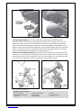
to turn to track a start. 6.2. How to set the mount in station. Point the telescope’s R.A. axis to
north. Release the altitude break figure 33 so that the R.A. inclination can be adjusted. Rotate the
latitude adjustment so that the inclination of the mount is the same as the latitude of observers. For
an observer in Munich the latitude is 48 degrees. The inclination angle (Ɵ) should be approximately
48 degrees. Make sure to re-tighten the altitude break. Now that the mount is pointing north and
has the observer’s location latitude your mount is set on station. This mean that the mount should
not be moved during observation. The two R.A. and Dec. axis can be used to position and point the
telescope to any part of the sky.
The altitude/latitude adjustment should NOT be used when
observing. Continuous use can cause wear or even break the knob.
Figure 3. Mount points north.
Figure 33. Release altitude break and adjust inclination.
Figure 34. Adjust inclination to latitude.
Figure 35. Check your latitude.

Reproduction of part or all of the contents of this document in any form is expressly prohibited other than for individual use only. All text, images and labels are property of Nimax Gmbh.
7. Using the accessories, a bit of math to
understand how all it works.
Using the accessories is easy and fun. To
change magnification simply swap eyepieces.
To get more magnification simply use the
barlow lens. But how does all of this work?
7.1. Power (magnification)
Your telescope has a focal length of 100mm.
This is approximately the distance between
the telescope lens and its focal point (very
similar to the distance between the focus
point of a loupe and the loupe lens). This is a
very important feature, that allows to
determine several interesting facts such as
magnification.
The magnification is determined by the
telescope’s focal length and the used
eyepiece. You probably noticed that the two
supplied eyepieces are Plössl 25mm and Plössl
10mm. This means that the Plössl 25mm is a
25mm focal length eyepiece while the Plössl
10mm is a 10mm focal length eyepiece.
To determine the magnification just divide the
telescope’s focal length by the eyepiece’s
focal length. Let’s give an example for our
telescope and the supplied eyepieces:
Telescope’s focal length is 1000mm.
Plössl 25 eyepiece’s focal length is 25mm.
1000𝑚𝑚
25𝑚𝑚 =40 𝑝𝑜𝑤𝑒𝑟
This means that the Plössl 25mm eyepiece
provides a 40x power (magnification). This
seems low, but when you try it, you will see a
bright image with some (very good) details.
7.2. Barlow Lens
The barlow lens is a very interesting device. It
is a negative lens, that multiplies the
telescope’s focal length. So a 2x Barlow
multiplies the original focal length by 2x, in
this case 1000𝑚𝑚 𝑥 2 = 2000𝑚𝑚.
A 3x Barlow lens multiplies by 3x.
Your telescope is supplied with a 2x Barlow
lens. When used with the Plössl 25mm
eyepiece you get 2x the power obtained
before 40 𝑝𝑜𝑤𝑒𝑟 𝑋 2𝑥 𝐵𝑎𝑟𝑙𝑜𝑤 = 80 𝑝𝑜𝑤𝑒𝑟
7.3. Erecting lens (not included)
The erecting lens gets you an upright image
view with the telescope. It also adds some
power like the barlow lens. The Erecting Lens
provides an extra 1.5x power.
7.4. Diagonal Mirror
This diverts the light coming from the
telescope to an angle of 45 or 90 degrees. It is
useful because it provides a more confortable
position when observing.
Here are some examples on how to use the
accessories.
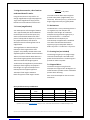
Some possible accessory combinations
Terrestrial
View
Moon
Deep Sky
Jupiter and
Saturn
Barlow Lens 2x
Yes
Plössl 25mm Eyepiece
Yes
Yes
Plössl 6.3mm Eyepiece
Yes
Power
Does not apply
153x
40x
80x
Questions? Visit our website www.astroshop.eu and drop us a line* nimax Gmbh Otto-Lilienthal-Str. 9 D-86899 Landsberg am Lech

Reproduction of part or all of the contents of this document in any form is expressly prohibited other than for individual use only. All text, images and labels are property of Nimax Gmbh.
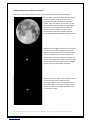
8. What can been seen with this telescope?
Below you will find some examples of what you can expect to see when using this telescope.
8.1. The Moon is one of the most spectular objects
to be seen through a telescope. Even a small
telescope will reveal high detail of the Moon’s
surface. You will be able to see the craters on the
Moon’s surface and other features like the Marea.
The moon is a very bright object. It is better to
observe it when the Moon is not full. Try the
crescent Moon and look for features along the
terminator (between illuminated and dark surfaces).
8.2. Jupiter is the biggest planet of our solar system.
It is also one of the favorite targets for beginners.
Galileo was able to discover that the four tiny dots
that turn around the planet were in fact part of
Jupiters system of moons. With this telescope you
will not only be able to see Jupiter’s planet disc with
its two major discernible bands, but also its biggest
moons, Io, Europa, Ganymedes and Callisto.
8.3. The “lord of the rings” of the night skies, Saturn
is by far the most popular target for small
telescopes. Saturn’s rings are discernible even at
60x magnification. In a very good night you will be
able to see the Cassini’s division (the darker band
on the Saturn’s rings).
-
 1
1
-
 2
2
-
 3
3
-
 4
4
-
 5
5
-
 6
6
-
 7
7
-
 8
8
-
 9
9
-
 10
10
-
 11
11
-
 12
12


Omegon 90/1000 EQ-2 User manual
- Category
- Telescopes
- Type
- User manual
Ask a question and I''ll find the answer in the document
Finding information in a document is now easier with AI
Related papers
Other documents
-
 ORION TELESCOPES & BINOCULARS Observer 70 EQ 9882 User manual
-
 Sky-Watcher NEQ3 User manual
-
 NiMAX Omegon 76/900 EQ-2 User manual
-
Levenhuk Skyline PRO 90 MAK User manual
-
DARTWOOD B09V4YY2VJ User manual
-
DARTWOOD 1008330595 User manual
-
Celestron XLT Series User manual
-
-
Canon 93517 User manual
-
Celestron 127 User manual


