Page is loading ...

RELEASED
4-30-18
REFERENCE NUMBER
INS-2320-00
40429 Brickyard Drive • Madera, CA 93636 • USA
559.438.5800 • FAX 559.438.5900
www.bklighting.com • [email protected]
B-K LIGHTING
THIS DOCUMENT CONTAINS PROPRIETARY INFORMATION OF B-K LIGHTING, INC. AND ITS RECEIPT OR POSSESSION DOES NOT CONVEY ANY RIGHTS TO REPRODUCE, DISCLOSE ITS CONTENTS, OR TO MANUFACTURE, USE OR SELL ANYTHING IT MAY
DESCRIBE. REPRODUCTION, DISCLOSURE OR USE WITHOUT SPECIFIC WRITTEN AUTHORIZATION OF B-K LIGHTING, INC. IS STRICTLY FORBIDDEN.
IMPORTANT SAFETY INFORMATION - READ, FOLLOW, AND SAVE THESE INSTALLATION INSTRUCTIONS
TOOLS
NEEDED:
By Others
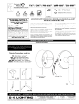
SM-AR™ / SM-MN™ / PM™ / PM-MN™ / WM™ / WM-MN™
• Product must be installed by a qualified person in a manner
consistent with its intended use and in compliance with the
National Electrical Code, Canadian Electrical Code, and all Local
and Provincial Codes.
• Follow product label information and instructions.
• Qualified Personnel must perform all servicing or relamping of
this product.
• Before wiring to power supply and during servicing or relamping,
turn off power at fuse or circuit breaker before service.
• The use of accessory equipment not recommended by the
manufacturer or installed contrary to instructions may cause an
unsafe condition. The use of damaged components may cause
an unsafe condition and void product warranty.
IMPORTANT SAFETY INFORMATION - READ, FOLLOW, AND SAVE ALL SAFETY
AND INSTALLATION INSTRUCTIONS
• Do not block light emanating from product in whole or part,
as this may cause an unsafe condition.
• Never operate the fixture with missing or damaged lens.
Lens must be cleaned on regular basis.
• Entire fixture may become extremely hot. Do not touch hot
lens or fixture body. Do not touch the lamp at any time. Use
a clean, dry, soft cloth to handle the lamp. Oil from skin may
damage the lamp and cause it to rupture.
• Replace lamp only with correct wattage and type of lamp
marked on fixture label.
• All gaskets, o-rings and sealing surfaces must be kept clean
during installation and service; failure to do this may cause an
unsafe condition and void product warranty.
INSTRUCTIONS PERTAINING TO
A RISK OF FIRE, OR INJURY TO
PERSONS IMPORTANT SAFETY
INSTRUCTIONS
Lighted lamp is HOT!
WARNING - To reduce the risk of FIRE OR INJURY TO PERSONS:
Turn off/unplug and allow to cool before replacing lamp.
Lamp gets HOT quickly! Contact only switch/plug when
turning on.
Do not touch hot lens, guard, or enclosure (see diagram/
picture).
Keep lamp away from materials that may burn.
Do no touch the lamp at any time. Use a soft cloth. Oil
from skin may damage lamp.
Do not operate the luminaire fitting with a missing or
damaged shield.
SAVE THESE INSTRUCTIONS
· Suitable for wet locations
IMPORTANT LISTINGS AND CERTIFICATIONS
Warning Hot Surface
Installation Instructions 1/8” Allen Wrench
Waterproof Wire Connectors
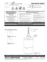
Universal
Mounting
Ring™
Canopy
Low Voltage
SM-AR - ArtiStar™ Surface Downlight™
TECHNOLOGY
with
& Low Voltage
SM-AR - ArtiStar Surface Downlight™
SM-MN - Micro Nite™ Surface Downlight™
PM - Pendant
PM-MN - Micro Nite™ Pendant
WM - Twin Pendant
WM-MN - Micro Nite™ Twin Pendant
This set of instructions works for:
WM
PM-MN
Please refer to the low voltage design guide at www.bklighting.com/lvguide before installation for proper wire selection.
WM-MN
SM-MN
PM

40429 Brickyard Drive • Madera, CA 93636 • USA
559.438.5800 • FAX 559.438.5900
www.bklighting.com • [email protected]
B-K LIGHTING
PROJECT:
TYPE:
IMPORTANT SAFETY INFORMATION LISTED ON REVERSE
READ, FOLLOW, AND SAVE ALL SAFETY AND INSTALLATION INSTRUCTIONS
RELEASED
4-30-18
REFERENCE NUMBER
INS-2320-00
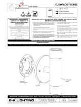
Installation Instructions
Phase 1 - Rough In
Installation of Back box
1. Install Conduit (By Others) to be used with
this product.
2. Install junction box (By Others) so that
front face is flush with finished ceiling. Seal
building envelope as per NEC.
3. Connect box to conduit and pull wires for
connections (See wiring diagram).
Additional Info
• Please follow National and Local electrical codes for your area.
• Use 4” round cast box (By Others)
• Suitable for through wire
• Suitable for installation into combustible materials.
• Rated for 90° C.
• Junction box, universal mounting ring screws, box mounting hardware
and gaskets (By Others)
3. Mount fixture using two (2) #10-24 hex screws
to installed back box using 1/8” Allen wrench.
Seal building envelope as per NEC. Do not
overtighten.
Phase 2 - Finish Installation of Fixture
1. Install universal mounting ring (supplied with
fixture) using #10-24 screws onto back box.
Align fixture mounting holes to final mounting
position.
2. Make watertight connections from remote
transformer to fixture leads using waterproof
wire connectors (By Others). See wiring
diagram.
LINE 12V
Fixture
COM
Remote
Transformer
COM
TECHNOLOGY
with
& Low Voltage
WIRING DIAGRAM
LED - For use with 12VAC
remote transformer or magnetic
transformers only. B-K Lighting cannot
guarantee performance with third party
manufacturers’ transformers.
Low Voltage - For use with 12VAC remote
transformer.
SM-AR™ / SM-MN™ / PM™ / PM-MN™ / WM™ / WM-MN™

RELEASED
10-30-15
REFERENCE NUMBER
INS000004
40429 Brickyard Drive • Madera, CA 93636 • USA
559.438.5800 • FAX 559.438.5900
www.bklighting.com • [email protected]
B-K LIGHTING
IMPORTANT SAFETY INFORMATION LISTED ON REVERSE
READ, FOLLOW, AND SAVE ALL SAFETY AND INSTALLATION INSTRUCTIONS
THIS DOCUMENT CONTAINS PROPRIETARY INFORMATION OF B-K LIGHTING, INC. AND ITS RECEIPT OR POSSESSION DOES NOT CONVEY ANY RIGHTS TO REPRODUCE, DISCLOSE ITS CONTENTS, OR TO MANUFACTURE, USE OR SELL ANYTHING
IT MAY DESCRIBE. REPRODUCTION, DISCLOSURE OR USE WITHOUT SPECIFIC WRITTEN AUTHORIZATION OF B-K LIGHTING, INC. IS STRICTLY FORBIDDEN.
LED & LOW VOLTAGE HALOGEN
2-1/4” Size
REPLACING LED BOARD/DRIVER AND OPTICS
1. Use 5/64” Allen wrench to loosen #8-32 stainless
set screw and remove cap.
4. Disengage LED board and driver assembly.
Replace with new board and driver assembly.
5. Reverse install LED board and driver.
6. With flat head screw driver rotate dial to desired
lumen output. Replace cap.
2. Space three fingers evenly around the optic
and gently rock optic to remove.
3. Use 5/64” Allen wrench to remove two (2)
#2-56 socket head cap screws on LED board,
grasp LED board and gently pull up to expose
quick disconnect.
TO CHANGE LUMEN OUTPUT (WHEN REQUIRED)
1. Use 5/64” Allen wrench to loosen #8-32 stainless
set screw and remove cap.
3. Place cap on fixture and tighten set screw.
Tighten screw to 1/2 inch pounds. Top of screw
should sit flush with fixture cap.
2. With flat head screw driver rotate dial to
desired lumen output.
This product is available with Adjust-e-Lume® (Patent Pend.) for DynamicLLumen Output Control
Warning! The light output of this product may be dynamically adjusted as desired to raise and lower light levels. Please ensure the xture is set
to the appropriate light level desired during installation.
Warning: Do not over tighten set screw.
Doing so will compromise O Ring seal and
will void warranty.
TECHNOLOGY
with
LAMP INSTALLATION OR RELAMPING IF REQUIRED FOR LOW VOLTAGE HALOGEN LAMPS
1. Use 5/64” Allen wrench to loosen #8-32
stainless set screw and remove cap.
3. Place cap on fixture and tighten set screw.
Tighten screw to 1/2 in-lbs. Top of screw
should sit flush with fixture cap.
Warning: Do not over tighten set screw.
Doing so will compromise O Ring seal and
will void warranty.
2. Firmly insert lamp pins into socket to make
connection. Rocking motion may be required.
Do not exceed the maximum wattage listed
on the fixture label before installing.
Replacement Instructions

1. Use 5/64” Allen wrench to loosen #8-32 stainless set
screw and remove cap.
2. Space three fingers evenly around the optic and
gently rock optic to remove.
4. Disengage LED board and driver assembly. Replace
with new board and driver assembly.
5. Reverse install LED board and driver by carefully
wrapping 18 gauge wires around driver and
inserting into fixture body. Secure LED board in
place with stainless steel screws.
6. Snap optics in place. Place cap on fixture and
tighten set screw.
3. Use 5/64” Allen wrench to remove two
(2) #2-56 socket head cap screws on LED
board, grasp LED board and gently pull up to
expose quick disconnect.
REPLACING LED BOARD/DRIVER AND OPTICS
REPLACING LOW VOLTAGE HALOGEN LAMPS
1. Use 5/64” Allen wrench to loosen #8-32 stainless
set screw and remove cap.
3. Place cap on fixture and tighten set screw. Tighten
screw to 1/2 in-lbs. Top of screw should sit flush
with fixture cap.
Warning: Do not over tighten set screw.
Doing so will compromise O Ring seal and will
void warranty.
2. Firmly insert lamp pins into socket to make
connection. Rocking motion may be required.
Do not exceed the maximum wattage listed
on the fixture label before installing.
LED & LOW VOLTAGE HALOGEN
1-5/8” Size
Replacement Instructions
RELEASED
5-1-18
REFERENCE NUMBER
INS000010
40429 Brickyard Drive • Madera, CA 93636 • USA
559.438.5800 • FAX 559.438.5900
www.bklighting.com • [email protected]
B-K LIGHTING
IMPORTANT SAFETY INFORMATION LISTED ON REVERSE
READ, FOLLOW, AND SAVE ALL SAFETY AND INSTALLATION INSTRUCTIONS
THIS DOCUMENT CONTAINS PROPRIETARY INFORMATION OF B-K LIGHTING, INC. AND ITS RECEIPT OR POSSESSION DOES NOT CONVEY ANY RIGHTS TO REPRODUCE, DISCLOSE ITS CONTENTS, OR TO MANUFACTURE, USE OR SELL ANYTHING
IT MAY DESCRIBE. REPRODUCTION, DISCLOSURE OR USE WITHOUT SPECIFIC WRITTEN AUTHORIZATION OF B-K LIGHTING, INC. IS STRICTLY FORBIDDEN.

RELEASED
1-31-14
REFERENCE NUMBER
INS-2097-00
40429 Brickyard Drive • Madera, CA 93636 • USA
559.438.5800 • FAX 559.438.5900
www.bklighting.com • [email protected]
B-K LIGHTING
THIS DOCUMENT CONTAINS PROPRIETARY INFORMATION OF B-K LIGHTING, INC. AND ITS RECEIPT OR POSSESSION DOES NOT CONVEY ANY RIGHTS TO REPRODUCE, DISCLOSE ITS CONTENTS, OR TO MANUFACTURE, USE OR SELL ANYTHING IT MAY
DESCRIBE. REPRODUCTION, DISCLOSURE OR USE WITHOUT SPECIFIC WRITTEN AUTHORIZATION OF B-K LIGHTING, INC. IS STRICTLY FORBIDDEN.
IMPORTANT SAFETY INFORMATION - READ, FOLLOW, AND SAVE THESE INSTALLATION INSTRUCTIONS
Warning Hot Surface
TOOLS
NEEDED:
By Others
5/32” & 5/64” Allen wrench
360SL™ Mounting System
Standard Adjustment
• Product must be installed by a qualified person in a manner
consistent with its intended use and in compliance with the
National Electrical Code, Canadian Electrical Code, and all Local
and Provincial Codes.
• Follow product label information and instructions.
• Qualified Personnel must perform all servicing or relamping of
this product.
• Before wiring to power supply and during servicing or relamping,
turn off power at fuse or circuit breaker before service.
• The use of accessory equipment not recommended by the
manufacturer or installed contrary to instructions may cause an
unsafe condition. The use of damaged components may cause
an unsafe condition and void product warranty.
IMPORTANT SAFETY INFORMATION - READ, FOLLOW, AND SAVE ALL SAFETY
AND INSTALLATION INSTRUCTIONS
• Do not block light emanating from product in whole or part,
as this may cause an unsafe condition.
• Never operate the fixture with missing or damaged lens.
Lens must be cleaned on regular basis.
• Entire fixture may become extremely hot. Do not touch hot
lens or fixture body. Do not touch the lamp at any time. Use
a clean, dry, soft cloth to handle the lamp. Oil from skin may
damage the lamp and cause it to rupture.
• Replace lamp only with correct wattage and type of lamp
marked on fixture label.
• All gaskets, O-rings and sealing surfaces must be kept clean
during installation and service; failure to do this may cause an
unsafe condition and void product warranty.
INSTRUCTIONS PERTAINING TO
A RISK OF FIRE, OR INJURY TO
PERSONS IMPORTANT SAFETY
INSTRUCTIONS
Lighted lamp is HOT!
WARNING - To reduce the risk of FIRE OR INJURY TO PERSONS:
Turn off/unplug and allow to cool before replacing lamp.
Lamp gets HOT quickly! Contact only switch/plug when
turning on.
Do not touch hot lens, guard, or enclosure (see diagram/
picture).
Keep lamp away from materials that may burn.
Do no touch the lamp at any time. Use a soft cloth. Oil
from skin may damage lamp.
Do not operate the luminaire fitting with a missing or
damaged shield.
SAVE THESE INSTRUCTIONS
· Suitable for wet locations · Additionally suitable for mounting within 4 ft. of the ground
IMPORTANT LISTINGS AND CERTIFICATIONS
360SL™ Knuckle
2. Rotate fixture at base and aim fixture to desired
horizontal location.
3. Use 5/32” Allen wrench to loosen #10-32 stainless
steel black oxide socket head cap screw at the
knuckle for vertical aiming purpose.
1. Use 5/64” Allen wrench to slightly loosen two (2)
#8-32 stainless steel set screws on the stem for 360°
aiming purpose.
4. Tighten two (2) #8-32 stainless steel set screws on
stem to secure horizontal aiming position.
Tighten #10-32 stainless steel black oxide socket
head cap screw to 15” minimum to 30” maximum
pounds to secure vertical aiming position.
Warning: Do not over tighten set screw. Doing
so will compromise O-ring seal and will void
warranty.

RELEASED
6-19-14
REFERENCE NUMBER
INS-2164-00
%ULFN\DUG'ULYH0DGHUD&$86$
)$;
ZZZENOLJKWLQJFRPLQIR#ENOLJKWLQJFRP
B-K LIGHTING
THIS DOCUMENT CONTAINS PROPRIETARY INFORMATION OF B-K LIGHTING, INC. AND ITS RECEIPT OR POSSESSION DOES NOT CONVEY ANY RIGHTS TO REPRODUCE, DISCLOSE ITS CONTENTS, OR TO MANUFACTURE, USE OR SELL ANYTHING IT MAY
DESCRIBE. REPRODUCTION, DISCLOSURE OR USE WITHOUT SPECIFIC WRITTEN AUTHORIZATION OF B-K LIGHTING, INC. IS STRICTLY FORBIDDEN.
IMPORTANT SAFETY INFORMATION - READ, FOLLOW, AND SAVE THESE INSTALLATION INSTRUCTIONS
Warning Hot Surface
TOOLS
NEEDED:
By Others
5/32” Allen Wrench
L.O.C.K.™ Knuckle System
Standard Adjustment
t 1SPEVDU NVTU CF JOTUBMMFE CZ B RVBMJGJFE QFSTPO JO B NBOOFS
DPOTJTUFOU XJUI JUT JOUFOEFE VTF BOE JO DPNQMJBODF XJUI UIF
/BUJPOBM&MFDUSJDBM$PEF$BOBEJBO&MFDUSJDBM$PEFBOEBMM-PDBM
BOE1SPWJODJBM$PEFT
t 'PMMPXQSPEVDUMBCFMJOGPSNBUJPOBOEJOTUSVDUJPOT
t 2VBMJGJFE1FSTPOOFMNVTUQFSGPSNBMMTFSWJDJOHPSSFMBNQJOHPG
UIJTQSPEVDU
t #FGPSFXJSJOHUPQPXFSTVQQMZBOEEVSJOHTFSWJDJOHPSSFMBNQJOH
UVSOPGGQPXFSBUGVTFPSDJSDVJUCSFBLFSCFGPSFTFSWJDF
t 5IF VTF PG BDDFTTPSZ FRVJQNFOU OPU SFDPNNFOEFE CZ UIF
NBOVGBDUVSFSPSJOTUBMMFEDPOUSBSZUPJOTUSVDUJPOTNBZDBVTFBO
VOTBGFDPOEJUJPO5IFVTFPGEBNBHFEDPNQPOFOUTNBZDBVTF
BOVOTBGFDPOEJUJPOBOEWPJEQSPEVDUXBSSBOUZ
IMPORTANT SAFETY INFORMATION - READ, FOLLOW, AND SAVE ALL SAFETY
AND INSTALLATION INSTRUCTIONS
t %POPUCMPDLMJHIUFNBOBUJOHGSPNQSPEVDUJOXIPMFPSQBSU
BTUIJTNBZDBVTFBOVOTBGFDPOEJUJPO
t /FWFS PQFSBUF UIF GJYUVSF XJUI NJTTJOH PS EBNBHFE MFOT
-FOTNVTUCFDMFBOFEPOSFHVMBSCBTJT
t &OUJSF GJYUVSF NBZ CFDPNF FYUSFNFMZ IPU %P OPU UPVDI IPU
MFOTPSGJYUVSFCPEZ%POPUUPVDIUIFMBNQBUBOZUJNF6TF
BDMFBOESZTPGUDMPUIUPIBOEMFUIFMBNQ0JMGSPNTLJONBZ
EBNBHFUIFMBNQBOEDBVTFJUUPSVQUVSF
t 3FQMBDF MBNQ POMZ XJUI DPSSFDU XBUUBHF BOE UZQF PG MBNQ
NBSLFEPOGJYUVSFMBCFM
t "MM HBTLFUT 0SJOHT BOE TFBMJOH TVSGBDFT NVTU CF LFQU DMFBO
EVSJOHJOTUBMMBUJPOBOETFSWJDFGBJMVSFUPEPUIJTNBZDBVTFBO
VOTBGFDPOEJUJPOBOEWPJEQSPEVDUXBSSBOUZ
INSTRUCTIONS PERTAINING TO
A RISK OF FIRE, OR INJURY TO
PERSONS IMPORTANT SAFETY
INSTRUCTIONS
-JHIUFEMBNQJT)05
8"3/*/(5PSFEVDFUIFSJTLPG'*3&03*/+63:501&340/4
5VSOPGGVOQMVHBOEBMMPXUPDPPMCFGPSFSFQMBDJOHMBNQ
-BNQHFUT)05RVJDLMZ$POUBDUPOMZTXJUDIQMVHXIFO
UVSOJOHPO
%POPUUPVDIIPUMFOTHVBSEPSFODMPTVSFTFFEJBHSBN
QJDUVSF
,FFQMBNQBXBZGSPNNBUFSJBMTUIBUNBZCVSO
%POPUPVDIUIFMBNQBUBOZUJNF6TFBTPGUDMPUI0JM
GSPNTLJONBZEBNBHFMBNQ
%POPUPQFSBUFUIFMVNJOBJSFGJUUJOHXJUIBNJTTJOHPS
EBNBHFETIJFME
SAVE THESE INSTRUCTIONS
· Suitable for wet locations · Additionally suitable for mounting within 4 ft. of the ground
IMPORTANT LISTINGS AND CERTIFICATIONS
L.O.C.K.™ Knuckle - (Locking ‘O’ Ring Compression Knuckle)
"JNGJYUVSFUPEFTJSFEBOHMF 6TF w "MMFO XSFODI UP TMJHIUMZ MPPTFO
TUBJOMFTTTUFFMTFUTDSFXPOUIFTUFNGPS¡BJNJOH
QVSQPTF
5JHIUFOTUBJOMFTTTUFFMTFUTDSFXVTJOHBw
"MMFOXSFODIUPTFDVSFBJNJOHQPTJUJPO
Warning: Do not over tighten set screw. Doing
so will compromise O-ring seal and will void
warranty.
/