Page is loading ...

113-90-693831Hearth and Home Technolgies • Oxford Direct/Natural Vent Installation Manual_R16 • 08/19
Direct/Natural Vent Gas Stove
Installation and Operating Instructions
Models: OXDV30SP
FIRE OR EXPLOSION HAZARD
Failure to follow safety warnings exactly could result
in serious injury, death or property damage.
• Donotstoreorusegasolineorotherammable
vapors and liquids in the vicinity of this or any other
appliance.
• WHAT TO DO IF YOU SMELL GAS
– Do not try to light any appliance.
– Do not touch any electrical switch; do not use
anyphoneinyourbuilding.
–Leavethebuildingimmediately.
– Immediately call your gas supplier from a
neighbor's phone. Follow the gas supplier's
instructions.
– If you cannot reach your gas supplier, call the
redepartment.
• Installation and service must be performed
by a qualified installer, service agency or the
gas supplier.
WARNING
!
Improper installation, adjustment, alteration, service
or maintenance can cause injury or property damage.
Refer to this manual. For assistance or additional
information consult a qualified installer, service
agency or the gas supplier.
WARNING
!
This appliance is for use only with the type of gas
indicated on the rating plate. This appliance is not
convertibleforusewithothergases,unlessacertied
kit is used.
This appliance may be installed in an aftermarket,*
permanently located, manufactured home (USA only)
ormobilehome,wherenotprohibitedbylocalcodes.
* Aftermarket: Completion of sale, not for purpose of
resale, from the manufacturer.
INSTALLER: Leave this manual with the appliance.
CONSUMER: Retain this manual for future reference.
DANGER
HOT GLASS WILL
CAUSE BURNS.
DO NOT TOUCH GLASS
UNTIL COOLED.
NEVER ALLOW CHILDREN
TO TOUCH GLASS.
A barrier designed to reduce the risk of burns from the hot
viewing glass is provided with this appliance and shall
be installed for the protection of children and
other at risk individuals.
20306543
5123
Oxford cover
CERTIFIED
S
AFETY BARRIER
Installation and service of this appliance should be performed by
qualied personnel. Hearth & Home Technologies recommends
HHT Factory Trained or NFI certied professionals.
This unit has been retired.
Service parts pages within have
been removed.
For replacement parts, please
refer to the individual service parts
list located on the brand website.

23-90-693831Hearth and Home Technolgies • Oxford Direct/Natural Vent Installation Manual_R17 • 09/19
TableofContents
PLEASE READ THE INSTALLATION & OPERATING INSTRUCTIONS BEFORE USING APPLIANCE.
Thank you and congratulations on your purchase of an Hearth & Home Technologies stove.
IMPORTANT: Read all instructions and warnings carefully before starting installation. Failure to follow these
instructionsmayresultinapossiblerehazardandwillvoidthewarranty.
Installation
General Information ..........................3
Requirements for the
Commonwealth of Massachusetts ...............4
California Safety Information ...................4
Oxford Dimensions ...........................5
Unpack Stove ...............................6
Installation Requirements ......................6
Locating the Stove ...........................6
Clearance Requirements ......................6
Parallel Installation ...........................7
Corner Installation ...........................7
Wall Centerline from Floor .....................7
Wall and Ceiling Clearances ...................7
Hearth Requirements .........................7
Gas Specications ...........................8
Gas Inlet and Manifold Pressures ...............8
High Elevations .............................8
Horizontal Termination - Direct Vent ONLY ........8
Vertical Termination - Direct Vent ONLY ...........9
Vent Termination Clearances ...................9
General Venting Information - Termination Location 11
Termination Clearances ......................12
Venting Requirements - Natural Vent ONLY ......12
Approved Vent System Components ............13
Install the Optional Fan ......................14
Venting System Assembly - Direct Vent ..........15
Install Vent Adapter Pipe
(HHT Vent Components) ....................15
Install Vent Adapter Pipe (Dura-Vent Components) . 16
Side Wall Termination Assembly ...............16
Vent Termination Below Grade .................18
Vertical (Through the Roof) Vent Assembly .......18
Venting System Assembly - Natural Vent .........19
Install the Vent Pipe .........................19
Install the Log Set ..........................20
Connect Gas Supply Line ....................20
Burner Information ..........................21
Air Shutter Adjustment & Instructions ............21
Complete the Assembly ......................22
Install ON/OFF Switch .......................22
Thermostat Connection (Optional) ..............23
Install the Front ............................23
Safety Barrier Installation .....................24
Operation
Your First Fire ..............................25
Pilot and Burner Information ..................25
Flame & Temperature Adjustment ..............25
Flame Characteristics .......................25
Lighting and Operating Instructions .............26
Troubleshooting - SIT NOVA 820 Gas Control System 27
Fuel Conversion Instructions ..................28
Conversion Procedure .......................28
SIT 820 Valve ............................28
Pilot Type 1 ..............................29
Pilot Type 2 ..............................29
Injector Orice Size ........................30
Maintenance
Annual System Inspection ....................30
Logset and Burner/Cleaning and Inspection ......30
Care of Cast Iron ...........................30
Cleaning the Glass .......................... 30
Glass Replacement .........................31
Gasket Replacement ........................31
Inspect the Vent System Annually ..............31
Check the Gas Flame Regularly ...............31
Stove Disassembly ..........................31
Wiring Diagram ............................32
Optional Accessories ........................ 33
Warranty ...................................34
Eciencies .................................36
= Contains updated information

3
3-90-693831 Hearth and Home Technolgies • Oxford Direct/Natural Vent Installation Manual_R17 • 09/19
General Information:
The Oxford Direct Vent, Model No. OXDV30SP, is a vented
gas appliance listed to the ANSI standard Z21.88-2014 and
CSA-2.33-2009 for Vented Room Heaters, and CSA 2.17-
M91, Gas-Fired Appliances For Use at High Altitudes.
The installation of the Oxford Direct Vent/Natural Vent Room
Heater must conform with local codes, or in the absence
of local codes, with National Fuel Gas Code, ANSI Z223.1/
NFPA 54 — latest edition and CSA B-149.1 Installation
Code. (EXCEPTION: Do not derate this appliance for
altitude. Maintain the manifold pressure at 3.5” w.c. for
Natural Gas and 10.0” w.c. for LP gas at maximum input.)
This appliance is only for use with the type of gas indicated
on the rating plate. This appliance is not convertible for use
with other gases unless a certied kit is used.
Installation and replacement of gas piping, gas
utilization equipment or accessories, and repair and
servicing of equipment shall be performed only by a
qualied agency, preferably NFI or WETT (Canada)
certied. The term “qualied agency” means any
individual,rm,corporation,orcompanythateitherin
person or through a representative is engaged in and
is responsible for (a) installation or replacement of
gas piping, or (b), the connection, installation, repair,
or servicing of equipment, who is experienced in such
work, familiar with all precautions required, and has
complied with all the requirements of the authority
having jurisdiction.
The Oxford Direct Vent/Natural Vent Room Heater
should be inspected before use and at least annually
by a qualied service agency. It is imperative that
control compartments, burners, and circulating air
passagewaysoftheappliancebekeptclean.
The Oxford Direct Vent/Natural Vent Room Heater and its
individual shut-o valve must be disconnected from the gas
supply piping during any pressure testing of that system at
test pressures in excess of 1/2 psig (3.5 kPa).
The Oxford Direct Vent/Natural Vent Room Heater must be
isolated from the gas supply piping system by closing its
individual manual shuto valve during any pressure testing
of the gas supply piping system at test pressures equal to
or less than 1/2 psig.
‘Direct Vent’ describes a sealed combustion system in which
incoming outside air for combustion and outgoing exhaust
enter and exit through two separate concentric passages
within the same sealed vent system. The system does not
use room air to support combustion. The Direct Vent system
permits the gas appliance to be vented directly to the outside
atmosphere through the side of the house or vertically
through the roof. Conventional venting systems (Natural
Vent) take air from the room for combustion and vent the
exhaust vertically through the roof to the atmosphere.
This appliance is approved for bedroom installations in the
U.S. and Canada.
This appliance may be installed in an aftermarket*
manufactured (mobile) home, where not prohibited by state
or local codes.
WARNING: Operation of this heater when not connected
to a properly installed and maintained venting system
can result in carbon monoxide (CO) poisoning and
possibledeath.
The Oxford Direct Vent/Natural Vent Room Heater, when
installed, must be electrically grounded in accordance
with local codes or, in the absence of local codes, with the
National Electrical Code ANSI/NFPA 70, (latest edition), or
of the current Canadian Electrical Code C22.1.
Due to high temperatures this appliance should be
located out of trac and away from furniture and
draperies.
WARNING: This appliance is hot while in operation.
Keep children, clothing, and furniture away. Contact
maycauseburnsorignitionofcombustiblematerials.
Children and adults should be alerted to the hazards
of high surface temperatures and should stay away to
avoidburnsorclothingignition.Youngchildrenshould
becarefullysupervisedwhentheyareinthesameroom
as the appliance.
Clothing or other ammable materials should not be
placed on or near the appliance.
Any safety screen, glass or guard removed for servicing
an appliance must be replaced prior to operating the
appliance.
The appliance area must be kept clear and free from
combustible materials, gasoline, and other ammable
vapors and liquids.
The ow of combustion and ventilation air must not
beobstructed.Theinstallationmustincludeadequate
accessibility and clearance for servicing and proper
operation.
WARNING: Do not operate the Room Heater with the
glasspanelremoved,crackedorbroken.Replacement
ofthepanelshouldbedonebyalicensedorqualied
service person.
Do not use this appliance if any part has been under
water. Immediately call a qualied service technician
to inspect the appliance and to replace any part of the
control system and any gas control which has been
under water.
Donotburnwood,trashoranyothermaterialforwhich
this appliance was not designed. This appliance is
designedtoburneithernaturalgasorpropaneonly.
Thisgasappliancemustnotbeconnectedtoachimney
ueservingaseparatesolid-fuelburningappliance.
CAUTION:Labelallwirespriortodisconnectionwhen
servicing controls. Wiring errors can cause improper
and dangerous operation.
Verify proper operation after servicing.
Proposition 65 Warning: Fuels used in gas, woodburning or
oil red appliances, and the products of combustion of such
fuels, contain chemicals known to the State of California to
cause cancer, birth defects and other reproductive harm.
California Health & Safety Code Sec. 25249.6
* Aftermarket: Completion of sale, nor for purpose of
resale, from the manufacturer.

43-90-693831Hearth and Home Technolgies • Oxford Direct/Natural Vent Installation Manual_R17 • 09/19
Requirements for the Commonwealth of Massachusetts
All gas tting and installation of this heater shall only be done
by a licensed gas tter or licensed plumber.
For all side wall horizontally vented gas fueled equipment
installed in every dwelling, building or structure used in whole
or in part for residential purposes, including those owned or
operated by the Commonwealth and where the side wall
exhaust vent termination is less than seven (7) feet above
nished grade in the area of the venting, including but not
limited to decks and porches, the following requirements
shall be satised:
InstallationofCarbonMonoxideDetectors
At the time of installation of the side wall horizontal vented
gas fueled equipment, the installing plumber or gas tter shall
observe that a hard wired carbon monoxide detector with an
alarm is installed on each additional level of the dwelling,
building or structure served by the side wall horizontal vented
gas fueled equipment. It shall be the responsibility of the
property owner to secure the services of qualied licensed
professionals for the installation of hard wired carbon monoxide
detectors.
In the event that the side wall horizontally vented gas fueled
equipment is installed in a crawl space or an attic, the hard
wired carbon monoxide detector with alarm and battery back-
up may be installed on the next adjacent oor level.
In the event that the requirements of this subdivision can not
be met at the time of completion of installation, the owner shall
have a period of thirty (30) days to comply with the above
requirements; provided, however, that during said thirty (30)
day period, a battery operated carbon monoxide detector with
an alarm shall be installed.
ApprovedCarbonMonoxideDetectors
Each carbon monoxide detector as required in accordance
with the above provisions shall comply with NFPA 720 and
ANSI/UL 2034 listed and IAS certied.
Signage
A metal or plastic identication plate shall be permanently
mounted to the exterior of the building at a minimum height
of eight (8) feet above grade directly in line with the exhaust
vent terminal for the horizontally vented gas fueled heating
appliance or equipment. The sign shall read, in print size no
less than one-half (1/2) inch in size, “GASVENTDIRECTLY
BELOW,KEEPCLEAROFALLOBSTRUCTIONS”.
Inspection
The state or local gas inspector of the side wall horizontally
vented gas fueled equipment shall not approve the installation
unless, upon inspection, the inspector observes carbon
monoxide detectors and signage installed in accordance with
the provisions of 248 CMR 5.08(2)(a)1 through 4.
Exemptions
The following equipment is exempt from 248 CMR 5.08(2)
(a)1 through 4:
• The equipment listed in Chapter 10 entitled “Equipment
Not Required To Be Vented” in the most current edition
of NFPA 54 as adopted by the Board; and
• Product Approved side wall horizontally vented gas fueled
equipment installed in a room or structure separate from
the dwelling, building or structure used in whole or in part
for residential purposes.
Manufacturer Requirements:
Gas Equipment Venting System Provided
When the manufacturer of Product Approved side wall
horizontally vented gas equipment provides a venting system
design or venting system components with the equipment,
the instructions provided by the manufacturer for installation
of the equipment and the venting system shall include:
• Detailed instructions for the installation of the venting
system design or the venting system components; and
• A complete parts list for the venting system design or
venting system.
Gas Equipment Venting System NOT Provided
When the manufacturer of a Product Approved side wall
horizontally vented gas fueled equipment does not provide
the parts for venting the ue gases, but identies “special
venting systems”, the following requirements shall be satised
by the manufacturer:
• The referenced “special venting system” instructions shall
be included with the appliance or equipment installation
instructions; and
• The “special venting systems” shall be Product Approved
by the Board, and the instructions for that system shall
include a parts list and detailed installation instructions.
A copy of all installation instructions for all Product Approved
side wall horizontally vented gas fueled equipment, all venting
instructions, all parts lists for venting instructions, and/or all
venting design instructions shall remain with the appliance
or equipment at the completion of the installation.
!WARNING
This product and the fuels used to operate this product
(liquid propane or natural gas), and the products of
combustion of such fuels, can expose you to chemicals
including benzene, which is known to the State of
California to cause cancer and reproductive harm. For
more information go to: www.P65Warnings.ca.gov.
California Safety Information

5
3-90-693831 Hearth and Home Technolgies • Oxford Direct/Natural Vent Installation Manual_R17 • 09/19
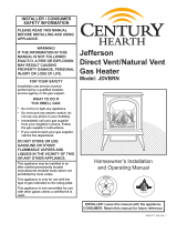
Oxford Direct Vent / Natural Vent Dimensions
C
L
Valve Inlet
23"
(584mm)
6³⁄₄"
(172mm)
24¹⁄₂"
(622mm)
C
L Valve
Inlet
5123
Oxford dims
28³⁄₈"
(721mm)
12¹⁄₂"
(318mm)
17"
(419mm)
4³⁄₈"
(111mm)
Refer to Figures 3 & 4 for Flue
Collar Centerline Dimensions
Figure 1 - Oxford dimensions.
Attention
TheOxfordstoveisshippedfromthefactoryasaDirectVentGasHeater.Thisheatermaybeconvertedintoa
NaturalVentunitintheeld.IfaNaturalVentheaterisdesired,theFSDHAGSLPDraftHoodmustbedirectly
installed to the top of the unit according to the installation instructions.
WhenthestoveisconvertedtoNaturalVent,ituses4”ventpipe.ForaestheticpurposestheHearth&Home
Technologiesdirectventsystemmaybeuseduptotheceiling.

63-90-693831Hearth and Home Technolgies • Oxford Direct/Natural Vent Installation Manual_R17 • 09/19
A
B
E
C
D
ST207b
Dutchwest
Stove locations
5/15/03 djt
Direct Vent System Only
A. Flat on corner wall D. Cross Corner
B. Room Divider E. Flat on wall
C. Island
Figure 2 - Possible stove locations.
Clearance Requirements:
MinimumClearancestoCombustibleMaterials
Measure side clearances as shown in Figures 5 and 6 from
the outer edge of the cast iron stove top. Measure rear
clearances from the outermost surface of the steel rear skirt.
The heater is approved for installation into an alcove
constructed of combustible materials to the dimensions and
clearances shown on the next page.
The same clearances apply in a standard parallel installation.
The surface of the Heater Is hot when it is in use. Young
children should be watched carefully when they are
in the same room when the Heater is in use, and they
should be taught to avoid the hot surface. Keep any
objects that can burn well away from the Heater, and
observetherecommendedclearancesthatfollow.
Locating the Stove:
In choosing a location for the stove, consider:
• The location of outside walls;
• Where additional heat is needed:
• Where family members gather most often;
• The vent system requirements.
NOTE: We do not recommend the use of wallpaper next
to this stove. Over time, radiant heat may cause the
wallpaper to shrink, or may adversely aect the binders in
the wallpaper adhesive.
WARNING
!
Due to high temperatures, the HEATER should be
located out of trac and away from furniture and
draperies.
Always maintain required clearances (air spaces) to
nearby combustibles to prevent re hazard. Do not
ll air spaces with insulation. All venting components
must maintain a 1” (25 mm) clearance to combustible
materials. Maintain a 6” (150 mm) clearance when using
a single wall pipe.
• The gas appliance and vent system must be vented
directly to the outside of the building and never be
attached to a chimney serving a separate solid fuel
or gas-burning appliance. Each direct vent appliance
must use its own separate vent system. Common
vents are prohibited.
• Refer to the manufacturer’s instructions included
with the venting system for complete installation
procedures.
WARNING
!
Installation:
Unpack the Stove
Using a 1/2" wrench, remove (4) lag bolts installed through
the shipping brackets and into the skid. Using a 7/16" wrench,
remove (2) 1/4-20 x 1/2” bolts holding the bracket onto the
legs. Tilt one side of the unit up and remove the shipping
bracket. Repeat previous steps to the opposite side.
Installation Requirements
The installation must conform with local codes or, in the
absence of local codes, with the National Fuel Gas Code,
ANSI Z223.1/NFPA 54 - latest edition. (EXCEPTION: Do
not derate this appliance for altitude. Maintain the manifold
pressure at 3.5” w.c. for Natural Gas, and 10” w.c. for
Propane).
In Canada, installation must be in accordance with the
current CSA B-149.1 Installation Codes and/or local codes.
Theinstallationshouldbedonebyaqualiedservice
person who is familiar with the building codes and
installation techniques appropriate for your area to
accomplishasafeandeectiveinstallation.
Your dealer or your local gas supplier will be able to
referaqualiedserviceperson.

7
3-90-693831 Hearth and Home Technolgies • Oxford Direct/Natural Vent Installation Manual_R17 • 09/19
Corner Installation:
Minimum Clearance and Flue Centerline
Direct Vent and Natural Vent
Stove Clearances A 4" (102 mm)
Pipe Centerlines B 14-1/2" (370 mm)
ST129c
Dutchwest
corner specs
5/15/03 djt
A
A
B
B
Figure 4 - Corner installation, minimum corner clearances and
ue centerline.
Wall and Ceiling Clearances
ARear Wall 4" (102 mm)
BMinimum Clearance 45-1/2" (1156 mm)
CMinimum Alcove Height 73-1/2" (1867 mm)
DMaximum Alcove Height 48" (1220 mm)
Sidewall Clearance 4" (120 mm)
A
C
D
ST1122
Min. clearance
B
Figure6- Dimensions and clearances to ceiling or alcove.
Wall Centerline from Floor
EectiveMinimum(A)
WallThimble 57-1/2" (1461 mm) (HHT Pipe)
Centerline 53-1/2" (1359 mm) (Simpson DuraVent Pipe)
ST1121
wall thimble
A
Figure 5 - Minimum wall thimble centerline.
Hearth Requirements
The heater must be installed on rigid ooring. When the
heater is installed directly on any combustible surface other
than wood ooring, a metal or wood panel extending the
full width and depth of the unit must be used as the hearth.
There are no other hearth requirements.
Parallel Installation:
Minimum Clearance and Flue Centerline
Direct Vent and Natural Vent
Stove Clearances A 4" (102 mm)
B4" (102 mm)
Pipe Centerlines C 15-1/2" (395 mm)
D9" (229 mm)
ST128b
Stardance
flue centerline
9/28/00 djt
C
L
C
L
B
D
C
A
Figure 3 - Parallel installation, minimum back and side clearances
and ue centerlines.

83-90-693831Hearth and Home Technolgies • Oxford Direct/Natural Vent Installation Manual_R17 • 09/19
The installation of your stove must conform with
local codes, or in the absence of local codes, with
the National Fuel Gas Code ANSI Z223.1/NFPA 54
- latest edition, or CSA B149.1 Installation code.
(EXCEPTION: Do not derate this appliance for
altitude up to 4,500 feet (1,370 m). Maintain the
manifold pressure at 3.5” w.c. for Natural Gas and
10.0”w.c.forLPGas.
High Elevations
Input ratings are shown in BTU per hour and are
certiedwithoutderationforelevationsupto4,500
feet(1,370m)abovesealevel.
For elevations above 4,500 feet (1,370 m) in USA,
installationsmustbeinaccordancewiththecurrent
ANSI Z223.1/NFPA 54 and/or local codes having
jurisdiction.
In Canada, please consult provincial and/or local
authorities having jurisdiction for installations at
elevationsabove4,500feet(1,370m).
HorizontalTermination-DirectVentONLY
The vent must rise vertically a minimum of 24” (610 mm) o
the top of the unit, before the rst elbow. The horizontal run
may extend up to 20’ (6 m) and include a vertical rise of up
to 40’ (12 m). (Figure 7) Horizontal termination must also
meet the criteria shown in Figures 9 through 11.
• Approved vent systems must terminate above and
including the heavy line in Figure 7.
• Two 45° elbows may be substituted for each single 90°
elbow.
• With a rise between 2’ - 5’, one 90° or two 45° elbows
may be used.
Figure 7 - Horizontal vent termination window.
20
19
18
16
15
14
13
12
11
10
9
8
7
6
5
4
3
2
1
0
1 2 3 4 5 6 7 8 9 10 11 12 13 14 15 16 17 18 19 20
Vertical Run (in feet)
(Measured from the appliance flue collar to the top of the vent pipe.)
Horizontal Run (in feet)
21
22
23
24
25
26
27
28
29
30
31
32
33
34
35
36
37
38
39
40
ST134a
FDV28
Horizontal
vent run
12/3/99 djt
areas modified
1/11/00 djt
May use up to three
90° Elbows
Unacceptable Venting
Conguration
Weight: Fully assembled; 202 lbs.
GasSpecications
Model Fuel
Gas
Control
Max.
Input
BTU/h
Min.
Input
BTU/h
2465 Natural Millivolt 28,000 20,000
2466 Propane Millivolt 28,000 19,000
Gas Inlet and Manifold Pressures
Natural LP (Propane)
Inlet Minimum 5.5" w.c. 11.0" w.c.
Inlet Maximum 14.0" w.c. 14.0" w.c.
Manifold Pressure 3.5" w.c. 10.0" w.c.
Oxford Direct Vent/Natural Vent Certied to:
ANSI Z21.88 / CSA 2.33 Latest Edition
Improper installation, adjustment, alteration, service
or maintenance can cause injury or property damage.
Refer to this manual for correct installation and
operational procedures. For assistance or additional
information consult a qualied installer, service
agency, or the gas supplier.
WARNING
!

9
3-90-693831 Hearth and Home Technolgies • Oxford Direct/Natural Vent Installation Manual_R17 • 09/19
VerticalTermination-DirectVentONLY
A vertical vent system must terminate no less than 8' (2.44
m) and no more than 40' (12 m) above the appliance ue
collar. A 2-1⁄4" restrictor plate (supplied) must be used where
specied in all vertically terminated vent systems. (Figure
8) NOTE: The restrictor plate supplied with the vertical
terminationshouldbediscarded.Installrestrictorplate
supplied with stove directly at stove outlet. A vertically
terminated vent system must also conform to the following
criteria:
• No more than three 90° elbows may be used.
• Two 45° elbows may be substituted for one 90° elbow.
No more than six elbows may be used.
• Vent must rise a minimum of 2 feet before oset is used.
• Termination height must conform to roof clearance as
specied in Figure 9.
20
19
18
16
15
14
13
12
11
10
9
8
7
6
5
4
3
2
1
0
20
1 2 3 4 5 6 7 8 9 10 11 12 13 14 15 16 17 18 19
Vertical Run (in feet)
(Measure from the appliance flue collar to the top of the vent pipe.)
Horizontal Run (in feet)
21
22
23
24
25
26
27
28
29
30
31
32
33
34
35
36
37
38
39
40
ST132a
FDV28
Vertical
vent run
12/3/99 djt
area
modified
1/11/00 djt
All Vertical Termi-
nations in this area
Require use of the
21⁄4" Restrictor Plate*
Vertical terminations
must be within this area
Unacceptable Venting
Conguration
No Restrictor Plate
Figure8- Vertical vent termination window.
*TheRestrictorPlateisusedonDirectVentInstallationsOnly
Vent Termination Clearances
When planning the installation, consider the location of the
vent terminal and clearances. Some of the most common
clearances to keep in mind are shown in Figure 10.
Important: All vent clearances must be maintained.
Check your vent termination clearances against
Figures9through11.
The vent should be placed so that people cannot be
burned by accidentally touching the vent surfaces when
the stove is operating.
The vent termination should be located where it cannot
be damaged by such things as automobile doors, lawn
mowers or snowblowers and it should be located away
from areas where it could become blocked by snow, etc.
Some considerations are:
• Obstructions or impediments to venting.
• Nearby combustible materials that could come into
contact with combustion exhaust gases.
• Other nearby openings {within 12” (305 mm)} through
which exhaust gas could reenter the building.
• All vegetation within 3’ (76 mm) that may interfere with
the draft.
Other factors that inuence where the installation will
be sited include the location of outside walls, where
additional heat may be desired in the home, where the
family members gather most regularly, and perhaps most
importantly, the distance limitations of the venting system.
IMPORTANT
Direct Vent Only
• The horizontal termination must not be recessed into
the exterior wall or siding.
• Horizontal vent runs must be level toward the vent
termination.
• Clearances around the vent termination must be
maintained.
• For installations using Simpson DuraVent pipe,
parallel installations with minimum wall clearance
have restricted access for connecting the Horizontal
Vent Cap straps to the vent pipe. See the maker’s
instructions for recommended installation procedures.

10 3-90-693831Hearth and Home Technolgies • Oxford Direct/Natural Vent Installation Manual_R17 • 09/19
Venting Termination Clearances
Your stove is approved to be vented either through the side
wall, or vertical through the roof.
• This unit does not require any opening for inspection
of vent pipe.
• Only HHT and Duravent venting components
specicallyapprovedandlabeledforthisstovemay
beused.
• Minimum clearances between vent pipes and
combustible materials is one (1”) inch (25 mm),
except where stated otherwise.
• Venting terminals shall not be recessed into a wall or
siding.
• Horizontal venting must be installed on a level plane
without an inclining or declining slope.
There must not be any obstruction such as bushes, garden
sheds, fences, decks or utility buildings within 24” from the
front of the termination hood.
Do not locate termination hood where excessive snow or ice
build up may occur. Be sure to check vent termination area
after snow falls, and clear to prevent accidental blockage
of venting system. When using snow blowers, make sure
snow is not directed towards vent termination area.
Location of Vent Termination
It is imperative the vent termination be located observing
the minimum clearances located on the following page.

11
3-90-693831 Hearth and Home Technolgies • Oxford Direct/Natural Vent Installation Manual_R17 • 09/19
GeneralVentingInformation-TerminationLocation
Canadian Installation1US Installations2
AClearance above grade, verenda, porch, deck or
balcony 12" (30cm) 12" (30cm)
BClearance to a window or door that may be
opened
6" (15cm) for appliance
< 10,000 Btuh (3kW). 12" (30cm) for appliances
> 10,000 Btuh (3kW) and < 100,000 Btuh
(30kW), 36" (91cm) for appliances > 100,00
Btuh (30kW) appliances > 50,000 Btuh (15kW)
6" (15cm) for appliances < 10,000 Btuh (3kW),
9" (23cm) for appliances > 10,000 Btuh (3kW)
and < 50,000 Btuh (15kW), 12" (30cm) for
appliances > 50,000 Btuh (15kW)
CClearance to permanently closed window 12" (305mm) recommend to prevent window
condensation.
12" (305mm) recommend to prevent window
condensation.
D
Vertical clearance to ventilated sot located
above the terminal within a horizontal distance
of 2 feet (610mm) from the center line of the
terminal
18" (458mm) 18" (458mm)
EClearance to unventilated sot 12" (305mm) 12" (305mm)
FClearance to outside corner see next page see next page
GClearance to inside corner (see next page) see next page see next page
HClearance to each inside of center line extended
above meter/regulator assembly
3' (91cm) within a height if 15' (5m) above the
meter/regulator assembly
3' (91cm) within a height if 15' (5m) above the
meter/regulator assembly
IClearance to service regulator vent outlet 3' (91cm) 3' (91cm)
J
Clearance to non-mechanical air supply inlet to
building or the combustion air inlet to any other
appliances
6” (15cm) for appliances < 10,000 Btuh (3kW),
12” (30cm) for appliances > 10,000 Btuh (3kW)
and < 100,000 Btuh (30kW), 36” (91cm) for
appliances > 100,000 Btuh (30kW)
6” (15cm) for appliances < 10,000 Btuh (3kW),
9” (23cm) for appliances > 10,000 Btuh (3kW)
and < 50,000 Btuh (15kW), 12” (30cm) for
appliances > 50,000 Btuh (15kW)
KClearance to a mechanical air supply inlet 6' (1.83m) 3’ (91cm) above if within 10’ (3m) horizontally
LClearance above paved sidewalk or paved
driveway located on public property 7’ (2.13m)† 7’ (2.13m)†
MClearance under veranda, porch, deck or balcony 12" (30cm)* 12" (30cm)*
NClearance above a roof shall extend a minimum of 24” (610mm) above the highest point when it passes through the roof surface, and any other
obstruction within a horizontal distance of 18” (450mm).
1 In accordance with the current CSA-B149 Installation Codes
2 In accordance with the current ANSI Z223.1/NFPA 54 National Fuel Gas Codes
† A vent shall not terminate directly above a sidewalk or paved driveway which is located between two single family dwellings and
serves both dwellings
* only permitted if veranda, porch, deck or balcony is fully open on a minimum 2 sides beneath the oor:
NOTE:
1. Local codes or regulations may require dierent clearances.
2. The special venting system used on Direct Vent appliances are certied as part of the appliance, with clearances tested and approved by the listing
agency.
3. Hearth & Home Technologies assumes no responsibility for the improper performance of the appliance when the venting system does not meet these
requirements.
V
V
V
V
V
V
V
X
X
X
D
E
B
B
B
C
B
M
B
A
J
K
F
L
VENT TERMINATION AIR SUPPLY INLET AREA WHERE TERMINAL IS NOT PERMITTED
H
I
Fixed
Closed
Operable
Operable Fixed
Closed
V
B
CFM145a
DV Termin Location
5/01/01 Rev. 12/05/01
sta
INSIDE
CORNER DETAIL
V
A
G
NN
CFM145a
Figure9 - Vent termination clearances.

12 3-90-693831Hearth and Home Technolgies • Oxford Direct/Natural Vent Installation Manual_R17 • 09/19
VentingRequirements-NaturalVentOnly
FP567
NVBR/NVBC VENTING RUNS
11/12/97
Venting Runs
Horizontal Run (in feet)
Vertical Run (in feet)
(Measured from top of the unit before any elbow)
A: Vertical installations up to 36 feet (12m) in
height. Up to an 18 ft. horizontal vent run can be
installed within the vent system using a
maximum of two 90-degree elbows or four
45-degree elbows.
B: Vertical installations up to 36 feet (12m) in
height. Up to a 24 ft. horizontal vent run can be
installed within the vent system using a
maximum of two 45-degree elbows.
(Ratio = 2/3, Hor./Vert.)
= Acceptable venting configuration
= Unacceptable venting configuration
36
34
32
30
28
26
24
22
20
18
16
14
12
10
8
6
4
2
1 2 4 6 8 10 12 14 16 18 20 22 24
A
B
NOTE: When venting staight vertical, without any
elbow, a minimum of 8 ft. vertical is required
off the top of the stove.
Figure 11 - Vent termination window - Natural Vent ONLY. NOTE: When using the FSDHAGSLP, the restrictor plate
supplied with the stove is not used.
Figure 10 - Termination clearances.
Outside Corner
Inside Corner
Termination Clearances
Termination clearances for buildings with combustible and noncombustible exteriors.
G =
Combustible
6" (152 mm)
Noncombustible
2" (51 mm)
F =
Combustible
6" (152 mm)
Noncombustible
2" (51 mm)
G
Balcony -
with no side wall
M =
Combustible &
Noncombustible
12" (305 mm)
M
Balcony -
with perpendicular side wall
M = 24" (610 mm)
P = 20” (508 mm)
M
F
Alcove Applications*
C
D
C
E
V
V
Combustible &
Noncombustible
V
V
V
E = Min. 6” (152 mm) for
non-vinyl sidewalls
Min. 12” (305 mm) for
vinyl sidewalls
O = 8’ (2.4 m) Min.
O
P
No.
of Caps DMin. CMax.
1 3’ (914 mm) 2 x DActual
2 6’ (1.8 m) 1 x DActual
3 9’ (2.7 m) 2/3 x DActual
4 12’ (3.7 m) 1/2 x DActual
DMin. = # of Termination caps x 3
CMax. = (2 / # termination caps) x DActual
*NOTE: Termination in an alcove space (spaces open only on one side and with an overhang) is permitted with the dimensions spec-
ied for vinyl or non-vinyl siding and sots. 1. There must be a 3’ (914 mm) minimum between termination caps. 2. All mechanical air
intakes within 10’ (1 m) of a termination cap must be a minimum of 3’ (914 mm) below the termination cap. 3. All gravity air intakes
within 3’ (914 mm) of a termination cap must be a minimum of 1’ (305 mm) below the termination cap.

13 3-90-693831Hearth and Home Technolgies • Oxford Direct/Natural Vent Installation Manual_R17 • 09/19
Approved Vent System Components
The heater must be vented to the outdoors through an
adjacent exterior wall or through the roof. The venting
system must be comprised of the appropriate listed venting
components specied on this page. These parts are available
from DuraVent Corporation or your Hearth and Home
Technologies Dealer.
See Figure 4 for dimensions relevant to the standard
minimum-vent kits.
HHTComponents*
Starter Pipe Assembly (incl. inner & outer
sections) 46DVA-ADP
90° Elbow, Blk. 46DVA-E90B*
45° Elbow, Gal. 46DVA-E45
6" Straight, Blk. 46DVA-06B*
9" Straight, Blk. 46DVA-09B
11" – 145⁄8" Adjustable Straight Section 46DVA-08AB
12" Straight 46DVA-12
24" Straight 46DVA-24B*
36" Straight 46DVA-36B
48" Straight 46DVA-48
Horizontal Vent Cap 46DVA-HC*
Wall Plate 46DVA-DC
Vinyl Siding Shield 46DVA-VSS
Snorkel Termination – 14" 46DVA-SNK14
Snorkel Termination – 36" 46DVA-SNK30
Wall Strap 46DVA-WS
Cathedral Ceiling Support Box 46DVA-CS
Storm Collar 46DVA-SC
Firestop Spacer 46DVA-FS
Flashing 0/12 - 6/12 46DVA-F6
Flashing 6/12 - 12/12 46DVA-F12
Wall Thimble 46DVA-WT
Wall Thimble Cover (Brass) 3PVP-TKV
Wall Firestop 46DVA-WFS
Attic Installation Shield 46DVA-IS
Co-Linear Vent Adapter 46DVA-GCL
Steel Chimney Conv. Kit A (6-5/8" - 8-5/8") 46DVA-KCA
Steel Chimney Conv. Kit B (6-5/8" - 10-1/2") 46DVA-KCB
Steel Chimney Conv. Kit C (6-5/8" – 13") 46DVA-KCC
Masonry Chimney Conversion Kit 46DVA-KMC
Vertical Termination Cap (High Wind) 46DVA-VCH
Vertical Termination Cap (Low Prole) 46DVA-VC
All DuraVent Straight vent pipe sections have a net length 1-1/2"
(37mm) less than the nominal dimension; i.e., a 6" (152 mm)
Straight pipe section has an eective length of 4-1/2" (115 mm).
DuraVent Components
SLP Horizontal Termination Kit (Termination
Cap, SLP24-BK, SLP6-BK, SLP6A-BK,
SLP90-BK, SLP-WT-BK & CCSLP)
SLP-SK-BK
Stove Adapter Kit (Includes 30' of 4" Flex,
adapters, wall thimble, masonry and ZC
ashing, 991DA Cap and Fasteners
LINK-STOVE
Trapezoid Termination Kit (3-1/8” - 4-3/4”) SLP-TRAP1
Trapezoid Termination Kit (5-1/4” - 9-1/4”) SLP-TRAP2
Rear Vent Termination Kit SLP-RVTK
Vertical Termination cap – High Wind
(includes storm collar) SLP-TVHW
Decorative Wall Thimble Cover SLP-WT-BK
Decorative ceiling restop – black SLP-DCF-BK
Cathedral ceiling support – black SLP-CCS-BK
4" (100mm) pipe length – black SLP4-BK
6" (150mm) pipe length – black SLP6-BK
12" Pipe length-black SLP12-BK
24" Pipe length-black SLP24-BK
36" (915mm) pipe length – black SLP36-BK
48" Pipe length-black SLP48-BK
3" - 6" (75 – 150mm) telescoping pipe
extension – black SLP6A-BK
3" - 12" telescoping pipe extension-black SLP12A-BK
45 degree elbow-black SLP45-BK
90 degree elbow-black SLP90-BK
Freestanding Draft Hood Adapter FSDHAGSLP
SL Snorkel Cap (Includes 1 pair of restops) SLK-SNKD
*CCSLP adapter is required when using HHT components.

14 3-90-693831Hearth and Home Technolgies • Oxford Direct/Natural Vent Installation Manual_R17 • 09/19
Install the Optional Fan
If you are installing the optional convection Fan Kit #2767
(FK26), continue here. If you are not installing a Fan Kit, go
to "Venting System Assembly".
1. The fan kit includes a Blower Assembly and a Rheostat
Assembly, connected by a cable. (Figure 12) The Blower
Assembly mounts to the bottom rear of the stove, and the
Rheostat mounts to the valve cover plate. The assembly
includes a ‘snapstat’ which automatically turns the fan
On (or O) above (or below) approximately 109°. The
Rheostat also provides a range of fan speed settings
from O (which overrides the snapstat function) to High.
Unpack and inspect the Blower assembly. Conrm that
the fan spins freely.
ST473
Fan parts
#2767 FK26
9/29/00
Snapstat
Bracket
Snapstat/
Extension
Assembly
Not Used on
RF Models
Not
Used on
Oxford
Blower
Assembly Connect to PC Board
on RF Models Only
Not Used
on RF
Models
Rheostat
Assembly
Figure 12 - Fan kit components.
2. Remove the rear skirt insert panel at the bottom of the
Rear Skirt (Figure 13) and fasten the blower assembly
to the rebox back with the two Phillips pan-head bolts
originally installed in the rebox back. (‘1’, Figure 14)
3. Attach the snapstat assembly to the snapstat bracket
with two sheet-metal screws. (‘2’, Figure 14) Attach
the snapstat bracket to the stove with a hex-head bolt
passing through the bracket and into the stove base. (‘3’,
Figure 14)
4. The rheostat control switch attaches to the left side of the
valve bracket at the front of the stove.
ST1123
rear skirt insert
Made in USA
Rear Skirt
Sheet Met-
al Screws
Rear Skirt Insert
Figure 13 - Remove rear skirt insert.
ST314
Fk26ce
attach fan
1/24/00
Star Washer
Sheet Metal Screws
Phillips
Pan
Head
Bolts
Star
Washer
Snapstat
1/4” - 20
Hex Bolt
Snapstat
Bracket
1
2
3
Figure 14 - Attach the fan assembly and the snapstat.
ST758
Dutchwest
attach rheostat
5/15/03 djt
Rheostat
Retaining Collar
Rheostat Knob
Figure 15 - Attach the fan rheostat.
This appliance is equipped with a three-prong (grounded)
plug for your protection against shock hazard and should
be plugged directly into a properly grounded three-prong
receptacle. Do not cut or remove the grounding prong
from this plug.
WARNING
!
• Remove retaining nut from shaft of rheostat. (if
preinstalled)
• Insert the rheostat through the hole in the back of the left
side of the valve bracket, aligning the locator pin with the
smaller hole in that bracket.
• Thread the retaining nut onto the shaft of the rheostat,
tightening with a wrench. Do not overtighten.
• Attach the control knob to the rheostat shaft.
• Use the wire tie to secure the fan and rheostat wire
harnesses together.

15
3-90-693831 Hearth and Home Technolgies • Oxford Direct/Natural Vent Installation Manual_R17 • 09/19
VentingSystemAssembly-DirectVent
For U.S. installations: The venting system must conform
with local codes and/or the current National Fuel Gas Code,
ANSI Z223.1/NFPA 54.
For Canadian installations: The venting system must
conform to the current CSA B149.1 installation code.
Install the Vent Adapter Pipe
(HHT Vent Components)
1. Install the Restrictor Plate: Consult the ‘Vent Run
Specications’ to determine whether the restrictor plate
is needed. If so, put the restrictor plate in place within the
inner ue collar as shown in Figure 16.
ST759
Dutchwest
restictor plate
5/15/03
Figure 16 - Install the restrictor plate only if required for the venting
conguration.
ST211
attach inner pipe
to next section
12/4/99 djt
CEMENT
First Section of
Vent Pipe
#8 x 1/2” Sheet
Metal Screws
4” Inner
Starter Pipe
Figure 17 - Connect the inner starter with the next section of inner
vent pipe.
ST760
attach inner assy
5/15/0 3 djt
CEMENT
Figure 18 - Attach inner assembly to ue collar.
ST761
attach inner assy
5/15/03 djt
Figure19 - Fasten outer pipe with #12 x 1/2” sheet metal screw.
5. Install the Outer Adapter Pipe: Apply a 1/4” bead of
cement around the inside wall of the pipe, about 1” from
the end. Insert the pipe over the stove ue collar, keeping
the vertical seam oriented to the back of the stove. Also,
be sure to align holes on the pipe with the holes on the
ue collar of the rebox. Fasten the pipe to the holes in
the ue collar with the #12 x 1/2” sheet metal screws
provided. (Figure 19)
2. Attach Inner Starter Pipe, (found in with the logset), to
the next section of inner pipe.
• Run a bead of sealant about 1/2” from the upper end
of the Inner starter pipe and join the two sections
together.
• Drill three pilot holes into the Inner Starter and secure
the assembly with three sheet metal screws. (Figure
17)
3. Dry t the Outer pipe assembly to the stove for the
purpose of determining the center line of the pipe on the
wall.
• Side Wall Terminations: Dry t the outer elbow with
the vertical outer vent and conrm the centerline
alignment with the wall thimble opening.
Remove the pipes and elbows before continuing with
Step 4.
4. AttachtheInnerVentAssemblytothestove:
• Run a bead of sealant around the bottom end of the
starter pipe and attach the assembly to the stove
using three 1/4-20 x 3/8” Phillips screws provided in
the parts bag. (Figure 18)

16 3-90-693831Hearth and Home Technolgies • Oxford Direct/Natural Vent Installation Manual_R17 • 09/19
ST762
dura vent
attach inner assy
5/15/03 djt
CEMENT
1/4-20 x 3/8
Phillips Screws
Inner Adapter
Pipe
Figure 20 - Simpson DuraVent - install inner adapter pipe.
ST763
DW dura vent
attach outer assy
5/15/03 djt
Figure 21 - Simpson DuraVent - install outer adapter pipe.
SideWallTerminationAssembly
1. Locate the vent opening on the wall. Refer to Figure 5,
to determine the opening centerline. It may be necessary
to rst position the stove and measure to nd the hole
location. Depending on whether the wall is made of
combustible materials, cut the opening to the size shown
in Figure 22. Combustible wall openings must be framed
as shown in Figure 22.
Hearth & Home Technologies System
VO584-100
Vent Opening
2/99 djt
93⁄8"
(240 mm
CombustibleWall Framing Detail
10"
(250 mm)
71⁄2"
(191 mm)
93⁄8"
(240 mm
10"
(250 mm)
DuraVent
System
Figure 22 - Locate vent opening
ZCS103
Zero Clearance Sleeve
& Firestop
12/6/99 djt
Sleeve
12"
(305 mm)
Max. Length
Firestop
Figure 23 - Assemble the wall sleeve and restop.
2. Measure the wall thickness and cut the wall sleeve
sections to proper length (MAXIMUM 12"). Assemble the
sleeve with the #8 sheet metal screws supplied. Attach
the restop plate to the sleeve end with the holes. (Figure
23) NOTE: The wall sleeve is required in combustible
walls only.
3. Install the Wall Firestop/Sleeve assembly into the wall
cutout and fasten the restop to the wall cutout framing
members. (Figure 23)
Install the Vent Adapter Pipe
(SimpsonDura-VentComponents)
1. Install the Restrictor Plate: Consult Figure 8 to
determine whether the restrictor plate is needed. If so,
place the restrictor plate into the inner ue collar. (Figure
16)
2. Discard the inner starter pipe shipped with the logset.
Using the starter pipe assembly, slide the inner section
out to allow access.
• Run a bead of sealant around the bottom end of the
starter pipe and attach the assembly to the stove using
three 1/4-20 x 3/8” Phillips screws provided in the parts
bag. (Figure 20)
3. Install the Outer Adapter Pipe: Apply a 1/4” bead of
cement around the outside surface, about one inch from
the crimped end. (Figure 21) Orient the vertical seam
to the rear, and insert the crimped end of the outer pipe
into the ue collar. Fasten with three sheet metal screws
provided.

17
3-90-693831 Hearth and Home Technolgies • Oxford Direct/Natural Vent Installation Manual_R17 • 09/19
X
ST764
DW
measure vertical vent
5/15/03 djt
Figure 24 - Determine the vertical pipe length.
ST215
measure thru wall
12/6/99 djt
X
Figure 25 - Measure the horizontal length.
ST216
install pipe thru wall
12/6/99 djt
Trim Collar
Wall
Sleeve
Wall Plate
Figure 26 - Install the horizontal pipe and wall plate parts.
Seal Both
Terminal Ends
ST217
install wall terminal
12/6/99 djt
Caulk Plate Joint with
Weatherproof Sealant
Figure 27 - Install the vent terminal.
10. For both Hearth & Home Technologies and
DuraVent Systems: Install the vent terminal. (Figure
27) Apply high temperature sealant one inch from the
ends of the inner and outer collars. Guide the inner and
outer vent termination collars into the adjacent pipes.
Double check that the vent pipes overlap the collars by
2”. Fasten the termination to the wall with the screws
provided, and caulk the joint with weatherproof sealant.
11. For Hearth & Home Technologies only: Install
Charcoal Gray Pipe Rings or Polished Brass Pipe Rings
at pipe joints, if desired.
5. Install rst the inner then the outer straight pipe section(s),
trimmed end down, to the point of the elbow. Drill 3 holes
through each joint and fasten with sheet metal screws.
6. Seal and install the elbow using 3 sheet metal screws at
each joint.
7. Measure, and cut if needed, the appropriate length of
pipe section needed to make the connection through
the wall. Include a 2” overlap; i.e. from the elbow to the
outside wall face, about 2” or the distance required if
installing a second 90° elbow. (Figure 25)
8. Slip the wall plate and trim collar over the interior end of
the horizontal pipe and install into the wall sleeve. Seal
the joint inside the wall plate if needed to keep cold air
from being drawn into the home.
9. Seal the ends and connect the horizontal pipe to the
elbow. Fasten the wall plate to the pipe with three sheet
metal screws. Slide the trim collar up against the wall
plate to cover the screws. (Figure 26)
For DuraVent pipe only: Install vent pipe by aligning the
locking system together, sliding the pipes together and
twisting clockwise.
• Install 90° elbow. Twist lock as before.
• Slide the wall plate over horizontal run before
attaching the horizontal run to the elbow. Fasten wall
plate to wall.
4. For Hearth & Home Technologies Vent Pipe only: If
necessary, measure to determine the vertical length (X)
of pipe required from the adapter pipe to the wall cutout
centerline, including a 2” (51mm) overlap at the joint.
(Figure 24) use a hacksaw or tin snips to trim the pipe as
needed.

18 3-90-693831Hearth and Home Technolgies • Oxford Direct/Natural Vent Installation Manual_R17 • 09/19
Vent Termination Below Grade
Install Snorkel Kit when it is not possible to meet the required
vent termination clearances of 12” (305 mm) above grade
level. The snorkel kit will allow installation depth of down
to 7” (178 mm) below grade level. The seven inches is
measured from the center of the horizontal vent pipe as
it penetrates the wall. If the venting system is installed
below grade, a window well must be installed with
adequate and proper drainage. (Figure 28)
NOTE: Be sure to maintain side wall clearances and vent
run restrictions. Refer to Figures 3, 4, 7, and 8.
1. Establish the vent hole through the wall.
2. Remove soil to a depth of approximately 16” (406 mm)
below the base of the snorkel. Install a window well (not
supplied). Rell the hole with 12” (305 mm) of coarse
gravel and maintain a clearance of at least 4” (102 mm)
below the snorkel. (Figure 28)
3. Install the vent system as described in the "Venting
SystemAssembly" section of this manual.
4. Be sure to make a watertight joint around the vent pipe
joint at the inside and outside wall joints.
5. Apply high temperature sealant around the inner and
outer snorkel collars. Join the pipes and fasten the
snorkel termination to the wall with the screws provided.
6. Level the soil to maintain a 4” clearance below the
snorkel.
ST1124
snorkel
Waterproof Seal
Around Pipe
Firestop
Window
Well
Drain
Snorkel
Termination
Cap
4” Clearance
Gravel
Figure 28 - Snorkel kit installation.
ST219
snorkel detail
12/6/99 djt
Recessed Wall
Firestop
Finishing
Collar
7” Pipe
Wall Plate
Sheet Metal
Screws and
Bracket
Wall Screws
and Anchors
Waterproof
Seal Around
Pipe
Figure 29 - Use extension brackets to mount snorkel against
recessed wall.
Vertical(ThroughtheRoof)VentAssembly
Note that all vertically terminated installations must include
the restrictor plate included with the stove. Refer to Figure 8.
Make certain the vent system conforms to all other
requirements for vertical termination.
This installation will require you to rst determine the roof
pitch and use the appropriate vent components. Refer to
Figures 8 and 9.
1. Locate the nal position of the stove, observing all
clearances for both the vent and the stove.
2. Plumb to the center of the inner (4”) ue collar from the
ceiling above, and mark that location.
3. Cut the opening:
Hearth & Home Technologies System:
9-3/8"x9-3/8"(240x240mm)
DuraVentSystem:10"x10"(254x254mm)
4. Plumb any additional opening through the roof or other
construction that may be needed. In all cases, the opening
must provide a minimum of 1" (25 mm) clearance to the
vent pipe.
5. Place the stove in its nal position.
6. Install restop(s) and Attic Insulation Shield as needed.
(Figure 30) If there is a room above ceiling level, a
restop must be installed on both the bottom and top
sides of the ceiling joists. If an attic is above ceiling level,
an attic insulation shield must be installed.
7. Install the appropriate roof support and ashing, making
certain that the upper ange of the ashing base is below
the shingles. (Figure 31)
If the foundation is recessed, use extension brackets (not
supplied) to fasten the lower portion of the snorkel. Fasten
the brackets to the wall rst, and then fasten to the snorkel
with self-tapping #8 x 1/2” sheet metal screws. Extend the
vent pipes out as far as the protruding wall face. (Figure 29)

19
3-90-693831 Hearth and Home Technolgies • Oxford Direct/Natural Vent Installation Manual_R17 • 09/19
ST222
vent thru ceiling
12/99
Attic Insulation
Shield
Firestop In
Upper Floor
Firestop in Ceiling
Use Four
8d Nails
Figure 30 - Install restops and attic insulation shield.
ST221
vent thru roof
12/99
Storm Collar
Sealant
Upper edge
of ange
goes under
upper
shingles
Flashing
(A, B of F)
Roof Support
Figure 31 - Roof support and ashing.
ST358
DW
Decorative
pipe around b-vent
5/15/03 djt
Decorative
7” Pipe
4” B-vent
Pipe
Draft Hood
Adapter
HHT Direct Vent
System may be used
from Draft Hood up
to the ceiling
Figure 32 - Decorative 7” pipe may be tted around the B-vent
pipe.
The stove, when installed as a Natural vent heater, includes
a vent safety switch. (Figure 63) Operating the stove when
it is not connected to a properly installed and maintained
venting system, or tampering with or disconnecting the vent
safety switch, can result in carbon monoxide (CO) poisoning
and possible death.
For U.S. installations: The venting system must conform
with local codes and/or the current National Fuel Gas Code,
ANSI Z22.1.
For Canadian installations: The venting system must
conform to the current CSA B149.1 installation code.
Install the Vent Pipe
Apply a bead of sealant around bottom end of inner starter
pipe (found in bag with logset) and attach to stove. Apply a
bead of sealant around top of inner starter pipe and install
the FSDHAGSLP Draft Hood according to Draft Hood
instructions. (Figure 33)
VentingSystemAssembly-NaturalVent
General Information
The heater is shipped from the factory as a Direct Vent
Heater. It may be converted to a Natural Vent heater by
installing the Model FSDHAGSLP Draft Hood Adapter.
The heater is approved for installation as a Natural Vent.
Hearth & Home Technologies Direct Vent pipe could be
used directly after the Draft Hood Adapter up to the ceiling,
then B-vent pipe must be used. Do not mix types of B-vent
pipe; use components from one maker or the other. Follow
the vent component maker’s instructions exactly. The
heater will also accept standard or enameled 7” (150 mm)
diameter pipe, around the Type B venting, for decorative
purposes only. (Figure 32)
NOTE: The restrictor plate supplied with the stove is
not used for Natural Vent applications.
8. Install appropriate pipe sections until the vent run
reaches above the ashing. The enlarged ends of the
vent sections always face downward.
9. Install the storm collar and seal around the joints.
(Figure 31)
10. Add additional vent lengths to achieve the proper overall
height.
11. Apply cement to the inner and outer termination collars
and install the terminal cap.

20 3-90-693831Hearth and Home Technolgies • Oxford Direct/Natural Vent Installation Manual_R17 • 09/19
ST767
DW
attach draft hood
5/15/03 djt
CEMENT
Figure 33 - Install draft hood adapter.
Install the Log Set
1. Remove the logs from their packaging, and inspect
each piece for damage. DO NOT INSTALL DAMAGED
LOGS.
2. Install the rear log by centering it to the rear of the rebox
on the sheet metal shelf, Figure 34. The log should touch
the back wall of the rebox when installed properly.
3. Place the right log by matching the hole on the underside
of the right log with the pin located on top of the rear log,
Figure 34. Set the front of the log on the burner and push
toward the right side of the rebox, the front right corner
of the log will touch the side wall of the rebox.
4. Place the left log by matching the hole on the underside
of the left log with the pin located on top of the rear log,
Figure 34. Set the front of the log on the burner and push
toward the left side of the rebox, the front left corner of
the log will touch the side wall of the rebox.
5. Lay the lava rocks in the open area of the burner in front
of and between the decorative grate and the right and left
logs. Use the lava rock to cover brackets on the burner,
Figure 34.
LG141
Stardance
Install logs 1
12/11/00 djt
Left Log Right Log
Rear Log Decorative Grate
Figure 34 - Install the back, left and right logs.
Connect the Gas Supply Line
Check the Rating Plate attached by a steel cable to the
rebox, to conrm that you have the appropriate rebox for
the type of fuel to be used. The Oxford may be converted
from one gas to another using the appropriate Fuel
Conversion Kit.
This appliance should only be connected by a
qualied gas technician. Test to conrm manifold
pressuresasspeciedbelow.
Theheaterand itsindividual shutovalvemustbe
disconnected from the gas supply piping during any
pressure testing of that system at test pressures in
excess of 1/2 psig (3.5 kPa).
The heater must be isolated from the gas supply
piping system by closing its individual manual
shutovalveduringanypressuretestingofthegas
supply piping system at test pressure equal to or
less than 1/2 psig.
Theremustbeagasshutobetweenthestoveand
the supply.
In order to connect Natural Gas, use a tting with
3/8” NPT nipple on the valve side and 1/2” natural
gas supply line with an input of 28,000 BTUs at a
manifoldpressureof3.5”andminimuminletsupply
foradjustmentof5.5”w.c.
Inorderto connectPropane,useattingwith3/8”
NPT nipple on the valve side and 1/2” propane
gas supply line with an input of 28,000 BTUs at a
manifoldpressureof10.0”andminimuminletsupply
foradjustmentof11.0”w.c.
CAUTION
!
Attach the rst section of venting to the draft hood.
Depending on the length of the individual venting sections
and the lengths of the decorative pipe (if installed), you may
need to slip the decorative pipe over the venting sections
before attaching upper sections to lower ones. The sections
of decorative pipe should be oriented with their seams (if
any) toward the wall; sections usually do not need to be
fastened at each joint, other than slip sections. If the layout
includes a slip section, this should be the last section of
pipe visible in the room, at the ceiling. Complete the venting
according to the vent maker’s instructions. Lava Rock
Placement
/