

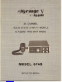
Your Hy-Range V is a full 23-channel AM/SSB transceiver designed
and licensed for Class 0 Citizen Band operation as designated by the
Federal Communications Commission (F .C.C.).
The Hy-Range V is a completely solid state compact unit of high
reliability and low power consumption. This transceiver utilizes
a highly advanced, unique system of frequency synthesization enabling
immediate operation on all 23 channels without the need of additional
crystals or adjustments. This unit also features a fine tune control
allowing you to make adjustments for stations which may operate
slightly off frequency. Additional features include an AN L (Auto-
matic Noise Limiter/NS (Noise Silencer) switch which reduces un-
desirable noises.
The Hy-Range V AM/SSB transceiver is designed to operate from
11.5 to 14.5 VDC. To obtain the best results from your transceiver,
it is suggested that you read all the instructions contained in this
manual.
Downloaded from www.Manualslib.com manuals search engine


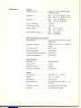
Receiver
Receiving system .......•.... Single conversion superheterodyne
for SSB and AM
Sensitivity AM 1/lV for 10 dB (S
+
N)/N
SSB 0.25"N for 10 dB (S +N)/N
Selectivity AM 7 kHz at 6 dB down
SSB 2.4 kHz at 6 dB down
Fine Tune Range ±800 Hz
Audio output power 3.0 watts
Squelch range AM 1/lV to 10 mV
SSB 0.7 /lV to 20 /lV
Intermediatefrequency AM 11.275 MHz
SSB 11.275 MHz
SSB (Single Side Band) Transmitter
SSB generation balanced ring modulator with crystal
latice filter
Frequency response 400 Hz to 2.6 kHz (+3, -10 dB up
down)
RF output power PEP 12 watts
Carrier suppression 40 dB down
Unwanted sideband suppression .. 40 dB down
Harmonic suppression 50 dB down
AM Transmitter
Modulation high level class B
Power input 5 watts
RF Power output 4 watts
Harmonic suppression 50 dB down
General
Power source ..........•... 13.8 VDC (11.5 - 14.5 V)
Speaker 3/4" x3" 8 ohm
Microphone dynamic type
Semi-conductors 34 transistors, 38 diodes, 1IC,
6 FET's
Frequency control synthesizer crystal controlled
Channels 23 channels all supplied
Downloaded from www.Manualslib.com manuals search engine

Licensing your Citizens
Two-way
Radio in the
United
States
NOTICE:
It
is illegal to transmit with this transceiver until you obtain
your citizens two-way radio Class D license. You are also required to
read and understand Part 95 of the Federal Communications Com-
mission rules and regulations before operation of this unit. License
application Form 505 is packed with your transceiver and Part 95
of the regulations may be available from your dealer; if not, you may
obtain copies from the Superintendent of Documents, Government
Printing Office, Washington, D.C. 20402.
It is also prohibited by the F.C.C. to adjust the transmitter circuit of
this unit unless you hold a current First or Second Class Radio-
telephone License.
We recommend that you refer all servIcing of any Hy-Gain products
to your nearest Hy-Gain warranty service center or consult your
Hy-Gain dealer or distributor for the service center location nearest
you. Do not tamper with any internal adjustments or settings - - such
tamperi ng can adversely affect the performance of you r transceiver
or may, in fact, cause your unit to operate beyond the limitations
set forth for Class D citizens two-way transceivers by the F.C.C.
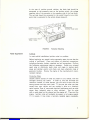
General Considerations
Choose a location which is convenient to the operating controls, and
will not interfere with the normal functions of the driver. The trans-
ceiver may be mounted to the underside of the instrument panel or
dashboard of a car, truck, boat, etc., by means of the special bracket
supplied with your transceiver.
Mounting Bracket
Attach the bracket to the underside of the instrument panel using
four or more screws (see Figure 3). Secure the transceiver to the
bracket by means of the large thumb screws.
DC Power Connections
The Hy-Range V may be operated from a nominal 12 VDC battery
source on negative or positive ground systems.
NOTE: Before making any power connections, determine whether
the vehicle has a negative or positive ground electrical system, then
make the following connections:
Connect the red lead to the vehicle
"+"
(positive) side of the electrical
system, and the black lead to the vehicle (negative) side of the
electrical system.
In the case of negative ground vehicles, the red lead should be con-
nected to the accessory post on the ignition switch, the voltage
regulator side of the ammeter or the accessory side of the fuse block.
The black lead should be connected to the metal firewall or any other
point that is connected to the vehicle chassis (ground).
Downloaded from www.Manualslib.com manuals search engine

Inthe case ofpositive ground vehicles,theblack leadshould be
connected to the accessory post on the ignitionswitch,the voltage
regulatorside of the ammeterorthe accessory side of the fuse block.
Thered lead should be connectedto the metalfirewall or anyother
point thatis connectedto the vehicle chassis (ground).
Tune·up
In mostmobileinstallations,ignition noise is a problem.
Before beginning any specialnoise suppressionsteps, be surethat the
vehicle is well-tuned.Cleanandtighten all electrical connections,
including alternator, battery,regulator and coil connections. Perform
thefollowing maintenancesteps as necessary. Solder anycrimped
sparkplug ordistributor leads;clean andregap or replace spark
plugs andignition points; and checkand cleanalternatorrings or
generator brushes. Retune the engineat the manufacturer'srecom-
mended intervals.
CorrectiveSteps
Usually several sources of noise are present in any vehicle,with the
strongest covering theothers.In order to find and eliminatethe
maximum number of noise sources, you will have to start with the
strong sources and then work back.To be sure the noise you hear
comes from your vehicle and not outsideit, drive to a relatively
quiet location (free of man-made electrical interference such as noisy
power lines, industrial noise or other vehicles). Test for noise
with a weak signal on the channel and the engine off.Then start the
engine.Ignition noise will probably be present at all engine speeds.
If it issevere, it may make anormally readable signal unreadable.
Downloaded from www.Manualslib.com manuals search engine

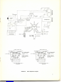
To reduce ignition noise, install resistor-type spark plugs if these
are not already installed. If non-resistance ignition wiring is used,
install a 10 k-ohm suppressor resistor at each spark plug tower of
the distributor. Install a coaxial capacitor at the ignition coil primary
as close to the coil primary as possible. This capacitor can be purchased
from an electronics parts company or an automotive electrical service
company.
A "whining" noise which varies with engine speed and continues with
the ignition turned off and the vehicle coasting in gear is characteristic
of the alternator. Check and clean it and install an alternator filter
(same sources as above).
An irregular, clicking sound which disappears at a slow idle charac-
terizes the voltage regu lator.Install a 4-ohm carbon resistor as close
to the field terminal of the regulator as possible, then a .002 f-lF
capacitor in series with and as close to the resistor as possible.
Connect the capacitor to ground. See the detail drawings of Figure 4.
Irregular popping noises which vary with road surfaces indicate static
discharge at any of several locations in the vehicle. Tighten loose
nuts and bolts and bond large areas such as the fenders, exhaust pipe,
firewall, etc. to the frame with lengths of heavy wire braid.
More Help
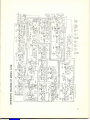
Figure 4 illustrates these noise suppression steps. Additional informa-
tion is available in the Radio Amateur's Handbook published by the
ARRL.
The Hy Range V transceiver does contain a noise silencer for reduction
of impulse noise. However, to get the best reception, noise suppression
steps shou Id be taken at the source of the noise.
Downloaded from www.Manualslib.com manuals search engine

~1PF COAXIAL
A
F
5k SUPPRESSOR
IN EACH SPARK
PLUG WIRE
iY1d/or
RESISTOR-TYPE
SPARK PLUGS
O.1pF COAXI~
SELF-TAPPING SCREW
and LOCK WASHER
(typical)
FERROUS BRACKET.
purchased seperately or
hand-formed
FERROUS BRACKET
purchased seperately or
hand-formed
SELF-TAPPING SCREW
and LOCK WASHER
(typical)
Downloaded from www.Manualslib.com manuals search engine

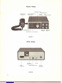
Antenna and External
Speaker Connections Antenna Connector.
Used for antenna connection, matches PL-259 standard type.
The antenna should be connected to the transceiver by means of
coaxial cable. Either RG-58/u or RG-8/u coaxial cable is ideal
for this purpose. The antenna lead-in cable shou Id be terminated with
a PL-259 type male coaxial connector which shou Id be attached to
the matching ANT connector at the rear of the transceiver.
Public Address (PA) Speaker Jack.
This jack is used for connection of an 8-ohm PA speaker for PA
operation.
Remote Speaker Jack.
This will be used to control the built-in speaker when operating the
transceiver with the optional telephone handset connected.
External Speaker (EXT. SP.) Jack.
This jack can be used with any 8-ohm earphone or speaker. Inserting
a 3.5 mm plug into the jack automatically silences the internal
speaker.
DC Power Connector.
This is used for connection of DC Power cord.
Power Switch.
This turns the power on or off.
ANL!NS (Automatic Noise Limiter/Noise Silencer) Switch.
With this switch placed in the released out position undesirable noise
will be considerably reduced in AM or SSB reception. When in the
depressed NS position annoying impulse noise will be blanked out.
This noise silencer circuit is effective for both AM and SSB reception.
The noise silencer will suppress much of the pulse-type interference,
"ignition noise," that is often a problem when operating mobile (or
for that matter, when you are operating as a base station). The depth
of the silencer and its relative effectiveness are determined by the
signal strength of the stations around you. This is known as the
"threshold level." If any station is putting out an S-9 or greater signal
on any channel, the effectiveness of the silencer will be at least
partially blocked. As far as when to use the silencer is concerned,
generally, it is left on all the time when you are operating mobile.
But when operating as a base station, you may also find it very helpful.
Don't confuse the action of a noise silencer with a noise limiter.
Noise limiters only clip off the peaks of the noise so that it is not
as annoying. This is helpful, but a noise silencer is much more
effective.
It
actually turns the receiver off momentarily so that no
noise at all is heard.
Downloaded from www.Manualslib.com manuals search engine

FineTuneControl.
When receiving SSB signals, adjust theFINE TUNE knob carefully
andset itwhere the incoming signal can be heard clearly.Because
of the characteristics of aSSB signal,it is extremely importantto
adjust this control. Withimproper finetuning adjustment,thesignal
will not be intelligible. The sound will bedistorted.SSB tuningwill
become easy asyou acquaint yourself with the operation of this
control. After adjusting it toclarifyonce, no adjustment is needed
if you stay on the same mode and channel, receiving the samestation.
LSB/USB/AM Switch.
This switch controls the mode of operation for thetransmitter and
receiver simultaneously and allowsselection of conventional AM
operation or SSB operation on either upper or lowerside band.In
order to communicate with another transceiver, you must use the
same operating mode.
PA/Squelch Control.
When operating the transceiver as a simple public address amplifier,
place thecontrol in the PA (fully counterclockwise position).Turning
thecontrol clockwise quiets the receiver when signals are not being
received and allows a quiet standby operation. It functionsonly in the
receive modeand does not affect the receiver volume when signals
are being received.To adjust:When no signalsare present, rotate
the squelch control clockwise until thereceiver isquieted.Incoming
signalswill automaticallyrelease the squelch.The squelch circuitis
effective for both AM and SSB reception.
NOTE:For normalCB operation, do not place the control in PA
position.
Volume control.
This varies the soundoutput from the built-inspeakerwhen receiving.
To increase the sound output,rotatethe knob clockwise and to
decrease,turn counterclockwise.
RF Gain Control.
Thiscontrols RF gain when receiving.To increase RF gain (reception
sensitivity) turn the knob clockwise and to decrease turn cou nter-
clockwise.
Channel Selector.
Continuously rotating switch selects anyone of 23 channels for
transmit and receive operation.
Signal Strength/RF Power Meter.
During reception,the bu ilt-in meter provides arelative indication of
signal strength in "S" unit on thelower scale and offers comparison
between one incoming signal and another.
Downloaded from www.Manualslib.com manuals search engine

During transmit, the meter will provide an indication of antenna RF
power on the upper scale. As you speak, the pointer should "flicker"
slightly, indicating that you are modulating the RF carrier.
Microphone Jack.
This accepts the push-to-talk microphone or optional telephone hand-
set.
Operating
Procedures Public Address Operation
Special provision has been made for Public Address operation,
utilizing the microphone and audio stages in the unit.
1. Connect a external PA speaker to the PA jack on the rear panel.
2. Place the PA/Squelch control in the PA position.
3. Press the push-to-talk button on the microphone and talk into
the mic. Your voice will be heard from the external speaker
which may be mounted on the exterior of a car, boat, or building.
NOTE: The volume control on the transceiver does not control the
speaker output during PA operation. However, the speaker output
can be varied by holding the microphone further away or speaking
softly.
CB Transmitter Operation
IMPO RTANT: Do not try to transmit without the CB antenna con-
nected to the antenna connector on the rear panel.
1. Insert the MIC plug in the MIC jack.
2. Make sure your antenna is securely connected to the ANT con-
nector.
3. Turn the power on as stated in this manual.
4. Set RF GAIN control to maximum temporarily.
5. Turn the SQUELCH knob counterclockwise fully.
6. Place the FINE TUNE knob at center position temporarily.
(See description on "FINE TUNE control")
7. Place the LSB/USB/AM switch in the desired position.
8. Place the AN L/NS push switch in either position.
9. Place the channel selector switch to a desired channel.
10. Adjust the VOLUME control for proper sound level.
11. To transmit press the push-to-tal k button on the microphone
and to receive release the button.
Downloaded from www.Manualslib.com manuals search engine


Ifyour receivershouldneed servicingunder the warranty, contact
yourHy-Gain dealerfor theHy-Gain Service Center nearest you.
Pleasecontact the ServiceCenterbefore shipping yourtransceiver to
him.All equipment returnedforwarranty repair must beaccompanied
byyour sales slip orinvoice, or a copy ofeither.
Units that have been modified cannot be accepted for repair.
Includeallinformation requested by the ServiceCenter. Thenpack
the unit as follows:
Checktheunit to see thatall parts and screws arein place. Then wrap
it in heavy paper or put itin aplastic bag.If the original carton
is not available,place theunitin a strong carton that isat least six
inches bigger in all three dimensions than the unit. Fill the carton
equally around the unitwith resilient packing material (shredded
paper,excelsior,etc.). Seal it with gummed paper tape,tie it with
a strong cord, and ship it by prepaid express, United Parcel Service,
orinsurl~d parcel post to the Hy-Gain Service Center.
It isvery important that the shipment be well-packed and fully insured.
Damage claims must be settled between you and the carrier ard this
can delay repairand return oftheunit to you.
Partscan be,Purchased from thefactory Customer Service Department.
Allparts ordersmust be prepaid or COD.When ordering,please
supply the following information:
1.model number oftheunit
2.serialnumber of the unit
3. description of the part
4.part number. (if available)
Address your letter to:
Hy-Gain Warranty
Service Department
490.0 Superior Ayenue
Lincoln, Nebraska 68505
Attn:National Service Manager
Downloaded from www.Manualslib.com manuals search engine

Hy-Gain Electronics Corporation warrants all products manufactured by it and bearing Hy-Gain model
numbers to be free from defective material and workmanship under normal use and service and
agrees to repair such products. If investigation discloses the defect to be the fault of our manufacture.
Hy-Gain's obligation under this warranty is limited to repairing any such product which, upon our
examination, proves to be so defective. All products repaired under such warranty must be returned
to the Hy-Gain factory, transportation prepaid by the purchaser, within ninety days from the date
of purchase .. 9
This warranty applies only to the original purchser.Upon receipt of equipment, the buyer is
responsible for checking the contents for damage. Any shipping damage should be referred to the
carrier.
This warranty does not apply to any Hy-Gain products which have been repaired, worked on, or
altered by persons not authorized by Hy-Gain to do so, or products to which the repair has injured
the stability or reliability of such product, or which has been the subject of mis-use, negligence, or
accident, or the serial number of which has been removed, altered, effaced, or in any other way
rendered unidentifiable. Neither does this warranty apply to any of our products which have been
connected, installed, used, or otherwise adjusted other than in accordance with instructions furnished
by Hy-Gain.Nor does Hy-Gain Electronics Corporation assume any liability for consequential
damages, and in any event, our liability shall in no case exceed the original purchase price of the
product.
Accessories supplied by, but not manufactured by Hy-Gain Electronics Corporation, shall carry only
such warranty as is available from the manufacturer of such goods and are specifically excluded from
Hy-Gain warranties.
This warranty is void if Hy-Gain shall inspect equipment and find that it has been modified,or
improperly installed or used. This warranty is expressly in lieu of allother warranties. Expressed
or implied, and all other obligations or liabilities on the part of Hy-Gain. No person, including any
dealer, agent, distributor, or representative of Hy-Gain is authorized to assume for Hy-Gain any
liability on its behalf, or in its name, except to rerer purchasers to this warranty.
Warranty Service Department
Hy-Gain Electronics Corporation
4900 Superior Avenue
Lincoln, Nebraska 68505
You must mail the warranty card in immediately.Then, in making a claim, you need only furnish the
model and serial numbers of the unit. However, if for some reason the card was not mailed, a copy
of a document, such as a sales receipt, recording the date, place, and proof c;>fpurchase may, at the
discretion of the service department, serve to establish your warranty.Your warranty claim letter
should include all pertinent details,along with the part or item numbers involved. Do not return
anything until requested to do so.You must supply the above information.
Any returned items must have prior authorization. Unexpected returns are greatly delayed in
handling. These delays can be avoided by writing in advance, furnishing the necessary information.
Hy-Gain reserves the right to make changes in design and improvements on its products without
assuming any obligation to install the same on any of its previously manufactured products. Further,
Hy-Gain reserves the right to ship new and/orimproved products which are similar to the form, fit,
and function of products originally ordered.
Downloaded from www.Manualslib.com manuals search engine

-
 1
1
-
 2
2
-
 3
3
-
 4
4
-
 5
5
-
 6
6
-
 7
7
-
 8
8
-
 9
9
-
 10
10
-
 11
11
-
 12
12
-
 13
13
-
 14
14
-
 15
15


Hy-Gain hy-range User manual
- Type
- User manual
- This manual is also suitable for
Ask a question and I''ll find the answer in the document
Finding information in a document is now easier with AI
Related papers

Other documents
-
Motorola GM338 Basic Service Manual
-
Kenwood MC-85 User manual
-
Realistic TRC-490-18 Owner's manual
-
-
Jackson 226-channel am/fm/ssb mobile Owner's manual
-
Midland ALAN 8001S EURO User manual
-
Uniden Grant XL Operating instructions
-
Midland Radio 79-290 User manual
-
Cobra 148 GTL ST User manual
-