60032

Nature Power 60032 User manual

  • Hello! I am an AI chatbot trained to assist you with the Nature Power 60032 User manual. I’ve already reviewed the document and can help you find the information you need or explain it in simple terms. Just ask your questions, and providing more details will help me assist you more effectively!
  • Can I use the Nature Power 60032 with a 24V battery system?
    What is the maximum solar input voltage?
    What type of batteries can I use with the Nature Power 60032?
    How do I set the battery type?
    What is the maximum current output for the DC-Load port?
    Can I manually turn the DC-Load port on or off?
    How do I access the unit's settings?
    Can I adjust the Bulk stage voltage for Lithium batteries?
V1.1-M 1Jun 2018
30 AMP Solar Charge Controller
 Manual
SAVE THESE INSTRUCTIONS
WARNING: Read and understand all instructions, warnings, and cautions before using this
product. Failure to follow the instructions, warnings, and cautions may result in serious personal injury
and/or property damage.

1. Important Safety Instructions
This section contains important safety information. Before installing or using the unit, READ
ALL instructions, and the provided cautionary markings. The unit contains no user-serviceable
parts. See Warranty section for how to handle product issues.
Warning: Fire and/or Chemical Burn Hazard
Do not cover or obstruct any air vent openings and/or install in a zero-clearance
compartment.
Warning: Failure to follow these instructions can result in death or serious injury
When working with electrical equipment or lead acid batteries, have someone nearby in
case of an emergency.
Wear eye protection and gloves.
Avoid touching your eyes while using this unit.
Keep fresh water and soap on hand in the event the battery acid comes in contact with
eyes.
If this occurs, cleanse right away with soap and water for a minimum of 15 minutes and seek
medical attention.
Batteries produce explosive gasses. DO NOT smoke or have an open spark or fire near the
system.
Keep the unit away from moist or damp areas.
Avoid dropping any metal tool or object on the battery. Doing so could create a spark or
short circuit that goes through the battery or another electrical tool and may create an
explosion.
Warning: Explosion hazard!
DO NOT use the unit in the vicinity of flammable fumes or gasses (such as propane tanks or
large engines).
Prolonged exposure to high heat or freezing temperatures will decrease the working life of
the unit.
Use only 12V or 24V battery systems (the voltage is auto-sensed by the unit).
Do not exceed the voltage and current ratings of the unit.
Use only solar arrays with 25/ 50Voc max for 12/ 24V nominal battery systems respectively.
Do not short circuit the solar array and/or the DC-Load port while connected to the unit.
This may permanently damage the unit.
Protect the unit from direct sunlight.
The unit is for INDOORS installation only.
Try to install the unit as close to the battery bank as possible. The battery acts as a low pass
filter reducing the chance for electrical noise, ripple, and interferences that may get into the
unit. We suggest battery wires no longer than 6 feet each one (+ and -) when possible.
Page of 21
Automatic Low Voltage Disconnect and Reconnect at the DC-Load port (on terminals 5-6).
Maximum regulated voltage on the Bulk stage (for Lithium and Program only).
The timers (up to three) for turning the DC-Load port on and off automatically according to
the time of the day. This can be done manually as well by using the “Enter” button in
Normal Operating mode.
The unit protects itself and provides the corresponding error alarms against the following
conditions:
Reversed polarity on either the battery and/or the solar panel ports.
Current overload condition on either the DC-Load and/or the solar panel ports.
Internal over temperature.
Page 3 of 21
2. Introduction
Noted: The charge controller always need to connected to a battery to
test and function properly.
Thank you for purchasing the Nature Power 30A Digital Solar Charge Controller. With our state
of the art, easy to use design, this product will offer you a reliable service to convert your solar
energy to charge your low voltage battery system in an effective and efficient way. It also
protects your battery from being overcharged by the solar panel, or over-discharged through
the DC loads connected to terminals 5-6 (if any). The unit uses
PWM (Pulse Width Modulation)
current control
techniques to regulate the charging current (and so the voltage) being supplied
to the battery by the solar panel (or panels).
The display is a comprehensive one, with 3-1/2 digits and symbols, allowing you to check
visually the operating status of the unit. It can show the digits and the corresponding symbols
on the display, such as arrows, battery, light bulb, and sun.
The current in Amps represents the net one flowing to and from the battery.
Additionally, the unit allows you the setting of different battery type-dependent parameters,
such as:
WARNING
This product can expose you to chemicals, including Di (2-ethylhexyl) phthalate (DEHP)
which is known to the State of California to cause cancer, birth defects or other reproductive
harm. For more information, go to www.p65warnings.ca.gov
ADVERTENCIA
Este producto puede exponerlo a productos químicos, incluidos Di (2-etilhexil) ftalato (DEHP)
que el estado de California sabe que causa cáncer, defectos de nacimiento u otros daños
reproductivos. Para obtener más información, vaya a www.p65warnings.ca.gov
Notes :
The use of the DC-Load port on terminals 5 and 6, is optional (you can keep them
disconnected). It is useful to provide an automatic Battery Under Voltage Load Disconnect
feature to the DC loads connected there, in an effort to avoid over-discharging the battery
when its state of charge (SoC) condition is getting low.
No external jumpers between each negative terminal are required.
Caution: Connecting DC loads on the terminals 5-6 that can draw either peak or continuous
currents that exceed the maximum rating of 30A, could damage the unit permanently, and that
would not be covered by the warranty. Heavy-duty DC loads, (such as inverters), have to be
connected directly to the battery terminals.
Operating Modes: The unit has the following three operating modes:
Normal Operating Mode: This is the default mode where the unit automatically starts and
eventually returns from other operating modes if no action is performed within 10 sec. It shows
the battery voltage (default) or the current (after pushing whatever arrow button), together with
all the symbols except the ones related to the timers and real time clock (
, , and PM)
Unit Setting Mode: This is the mode for setting and editing all the programmable parameters of
the unit. In this mode, only the symbols related with the specific parameter being shown are
displayed, except the battery symbol, which should remain flashing in all the operating modes.
The only way for getting out of this mode and returning to the Normal Operating Mode is waiting
10 sec without touching any push button.
Setting Display Mode: This is the mode for reading the settings without the risk of changing them
accidentally. It is very similar to the Unit Setting Mode (e.g. in regards to the symbols and the
sequence of the parameters) except that the arrows push buttons are used for scrolling up or
down circularly through the settings other than for increasing or decreasing their values.
Page 4 of 21
3. Understanding the unit
Caution: This unit is designed for use with V or V nominal Battery Systems only
1 2 3 4 5 6
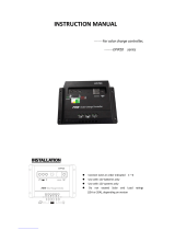
Solar Panel Battery DC Load Chassis Ground
Terminals 1 and 2 are the input port for the solar panel connection.
Terminals 3 and 4 are used for the battery connection. They act as both an output port, for
charging the battery from the solar panel, and an input port for discharging the battery to the
DC loads (if any) through the controller (on terminals 5 and 6).
Terminals 5 and 6 are the output port for the DC loads with a total current draw equal or less
than 30A, such as DC light bulbs and small to medium power DC appliances.
Push Buttons Functions: (Menu, Enter, Up , and Down ).
In Normal Operating Mode
Press once to enter the Setting Display Mode to read the unit settings without
the risk to change them accidentally. Once in the Setting Display mode, press the
Up/Down buttons to scroll circularly through the parameters settings (Real Time
Clock, Battery Type, Lithium/Program Bulk Voltage, DC-Load Voltage Disconnect
and Reconnect on terminals 5-6, and the start and duration of the timers).
In Setting Display Mode:
Press once to exit the Setting Display Mode and return to Normal Operating Mode;
(the same occurs automatically without pressing any push button for 10 sec.)
In either Normal Operating Mode or Setting Display Mode:
Press and hold for more than 3 seconds to enter the Unit Setting Mode. Once in
the Unit Setting Mode, you need to wait 10 sec without pressing any push button
to return to Normal Operating Mode.
In Unit Setting Mode:
Press once to skip to the next parameter setting if no change is required in the
one being displayed.
In Normal Operating Mode
Press and hold for more than 3 sec to turn manually the DC-Load port ON or OFF
In Unit Setting Mode:
Press once to confirm or save the setting and proceed to the next parameter
setting (see more details in section 9 ‘Understanding the Unit Setting Mode’).
In Setting Display Mode:
Nothing happens. It does not have any effect.
In Normal Operating Mode
Press either the Up or Down button to change the display in between battery
voltage and charging current measurements.
Press and hold both buttons for 3 seconds to read the software revision
number (e.g. “r1.7”).
In Unit Setting Mode:
Press the Up or Down button to edit the parameters settings.
In Setting Display Mode:
Press the Up or Down button to scroll up or down through the settings reading.
Page 5 of 21
4. Three-stage charging algorithm:
The unit provides a 3-stage charging algorithm having a Bulk, then Absorption and then Float stage
sequence. During the Bulk stage, the battery accepts all the possible current from the solar panel
(if available) in an effort to charge the battery and so raising its voltage. Once the battery voltage
reaches the maximum one
(depending on the setting), the unit passes from Bulk to Absorption
stage, keeping that maximum voltage by reducing the charging current if necessary under a PWM
regulation approach. When entering the Absorption stage, a two-hour timer starts running. During
that period, if the battery voltage drops 0.3V below the Absorption voltage
, the timer will
restart. When the Absorption timeout occurs, the unit pass to the Float stage supplying a lower
voltage to maintain the battery in a fully charged state. The controller will automatically restart the
full charging cycle if it senses the battery bank is discharged to less than 12.5V/25V in 12V/24V
battery systems respectively.
Note
: The maximum voltage in Bulk stage corresponds to the Absorption one, being the
threshold to pass from Bulk to Absorption stage. herever its setting is allowable to the user, the
display will show the Bulk symbol other than the ABS one (see the section  for more details).
5. Installation Instructions:
Caution: Before installing the unit, please verify the rating of the solar panel, the battery type and
its nominal voltage, and the total power consumption of the DC loads.
Max.
Current
Battery
Voltage
Battery
Type
Maximum Solar Panel
Rating
Allowable
Direct
/Min.
wire Gauge
respectively
30A
12V or 24V
(Self
detection)
Gel, AGM,
Flooded, Lithium
Programmable
480W-12V
(12V system)
960W-24V (24V system)
#6 / #10 AWG
Note : As per the physical connector of the unit, and/or the crimping terminals being used. However,
thicker wires can be used for the solar panel array to compensate excessive power losses (resistance) on
long runs, by reducing their thickness on the last edge inches (e.g. by splicing two 4” long thinner wires).
That bottleneck would not affect the power losses, being insignificant in 4” long thinner wires and always
thick enough for the unit maximum current rating.
Step 1: Select the Battery type. Refer to the next section (“Understanding the Unit Setting”).
Step 2: Connect the positive and negative terminals of the PV, Battery and DC Loads
accordingly. Check their polarity before connecting.
Unit Mounting: Select an appropriate mounting Indoor location not susceptible to extreme
heat, humidity, and dirty conditions. The unit can be oriented in any direction. Allow free space
around the unit for heat dissipation purposes. Install the controller as close as possible to the
battery (the battery acts like a low pass filter, helping the reduction of electrical noises and
interferences on the DC wiring). Hold the controller against the mounting surface and mark the
positions of its mounting holes on its flanges. Then, make the pilot holes with a drill.
Page 6 of 21
6. Display Functions and Symbols:
7. Understanding the Display Symbols:
Meanings of the basic display symbols:
Solid: The solar panel is detected (--> its voltage, on the terminals 1-2, is higher than 6.2V or
11.2V*). It could take up to 10 sec to be updated to a new Off condition (since the moment its
voltage drops below 4.2V or 9V*respectively). *Note: according to the version of the unit.
Flashing: The battery is detected. Its voltage has to be higher than about 6.2 6.4V for the
controller to operate. It should be flashing permanently in all the operating modes.
Otherwise, the controller must be reset as indicated in the troubleshooting table section 14
(point
). Purpose: To indicate that the unit is alive and running OK.
Solid: The DC-Load port (on terminals 5-6) is ON.
Flashing: The DC-Load port should be ON but it is forced to be OFF due to one or more of the
following alarm conditions: a) E05: DC-Load Under Voltage Shutdown; b) E03: DC-Load Overload;
c) E04: Unit Over Temperature Shutdown. Otherwise, the DC-Load port would be already ON.
Since the DC-Load port is disconnected, the corresponding flashing current flow arrow conse-
quently goes off (if it was on). PURPOSE: This is to alert the user that the DC Loads (connected
to terminals 5 and 6) could start running at any time, once those error conditions disappear.
Flashing: Flow of current in between the symbols above. It should remain flashing (not solid).
It takes up to 10 /30 sec to be updated to a new flashing/off condition respectively.
These Symbols show the charging and discharging
status in the Normal Operating Mode only
Symbols shown in all the modes and according to
the specific conditions at the moment
Push buttons with multiple functions, according
to the specific operating mode at the moment
Meanings of the basic display symbols combined:
Symbol Description (with the battery/bulb symbols always flashing/solid respectively)
Solar power is being supplied to the battery. The DC-Load port is ON and the
load is drawing current from the battery.
Solar power is being supplied to the battery. The DC-Load port is ON and there
is no load, or it is very low to be detected .
Solar power is being supplied to the battery. The DC-Load port is OFF.
The solar panel is detected but does not have enough voltage to charge the
battery. The DC-Load port is ON and the load is drawing current from the battery.
Page of 21
The solar panel is detected but does not have enough voltage to charge the
battery. The DC-Load is ON and there is no load, or it is very low to be detected.
The solar panel is unavailable (e.g. at night or disconnected). The DC-Load port
is ON and the load is drawing current from the battery.
The solar panel is unavailable (e.g. at night or disconnected). The DC-Load is
ON and there is no load, or it is very low to be detected.
The solar panel is unavailable (e.g. at night or disconnected). The battery
is connected. The DC-Load port is OFF.
Display Symbols ‘‘‘ modes
These symbols indicate the battery type. Note: Some units may have symbols
showing lo  Li  ro instead of looded  Lithium  rogram respectively.
The related symbol shows the charging stage at the moment (Bulk, Absorption, or
Floating). They are mutually exclusive (only one at a time). They may take up to 10
sec to be updated to a new different stage. In both Unit Setting and Setting
Display modes having either Lithium or Program selected, the “Bulk” symbol goes
on to indicate the Absorption voltage setting (see note
)
(mutually
exclusive)
In Unit Setting and Setting Display :
The display is showing 1 of the 3 DC-Load ON or OFF timers values, as per the
symbol being shown, which flashes periodically with 1, 2, or 3 pulses pattern to
indicate that the value corresponds to the timer 1, 2, or 3 respectively.

These alarm clock symbols are not showed when they are disabled.
Note
: these symbols never appear in Normal perating ode.
In any condition, the ‘24V’ symbol indicates that a 24V battery system has been
detected and is in use. Otherwise, It remains OFF indicating a 12V battery system.
In Normal Operating Mode: The display is showing the net battery discharging
current in Amps. In other words, the charging current from the solar panel is less
than the discharging current by the DC loads on terminals 5-6, so the battery is
discharging supplying the difference of current and showing it on the display. 
: Solid/Flashing means that the
display is showing the DC-Load port Disconnect /Reconnect Voltage respectively.
The display shows time/Net battery charging or discharging current/
Battery voltage/Timer setting/Error code, e.g. 12:04/21.2/12.3/C01 or
C00/E02 respectively.
This symbol indicates the afternoon time (‘Post Meridiem’).
The display is showing the net battery charging/discharging current in Amps.
The display is showing the battery voltage in Volts.
Error is detected and the display is showing its code in the E01-E05 range.
Page of 21
8. About the net battery charging and discharging conditions shown on the display:
As already mentioned in the previous table, the current in Amps shown on the display is the net
one, being the result of the one provided by the solar panel minus the one being drawn by the DC
loads connected to the terminals 5-6 of the unit (if any).
Note
: The net current shown on the display (so the charging and discharging condition) relates
to the solar panels and DC Loads (if any) connected to the corresponding ports on the controller.
hatever current being supplieddrawn tofrom the battery by other external sourcesloads
respectively that are connected directly to the battery terminals, are out of the controller moni-
toring range. If that were the case, the displayed net current could be meaningless or incomplete.
Some examples in Normal Operating Mode:
The following table shows several conditions for illustration purposes. It is based on a 12V AGM
type battery with a 5.7A DC load. All the possible combinations are not shown.
Display/Case # Current flows Description
Case #1: Display showing no solar panel power available and the DC-Load port is OFF
->Flashing as should be always to indicate unit is running.
->Off, to indicate no current is flowing from the solar
panel, at least not a perceptible one. It is either disconnected
or at night condition, so its arrow is not shown.
->Off, to indicate DC-Load port is OFF, so no current from
the battery to the DC-Load terminals -->No arrow is shown
AGM -->Battery type setting is shown, being, in this case, AGM
See the net current in Amps by pushing the or buttons
Neither charging nor discharging.
Case #2-1: Display showing no solar panel power available and the DC-Load port is ON
->Flashing as should be always to indicate unit running.
->Off to indicate that no current is flowing from the solar
panel, at least not a perceptible one. It is either disconnected
or at night condition, so its arrow is not shown.
->On, to indicate DC-Load port is ON, so there is a current
from the battery to the DC-Load terminals -->arrow is flashing
AGM -->Battery type setting is shown, being, in this case, AGM
See the net current in Amps by pushing the or buttons
Net battery current = -5.7A (discharging)
->Solid ON, indicating discharging (negative) current
Page 9 of 21
Page 10 of 21
Case #2-2: Display showing solar panel power available and the DC-Load port is OFF
->Flashing as should be always to indicate unit running.
-->On to indicate current is flowing from the solar panel
to the battery, so the corresponding flow arrow is flashing
->Off, to indicate DC-Load port is OFF, so no current from
the battery to the DC-Load terminals -->No arrow is shown
AGM -->Battery type setting is shown, being, in this case, AGM
See the net current in Amps by pushing the or buttons
Net battery current = 23.9A (charging)
Bulk -->On, as the charging stage at the moment
Case #2-3: Display showing solar panel power available and the DC-Load port is ON
->Flashing as should be always to indicate unit running.
-->On to indicate current is flowing from the solar panel
to the battery, so the corresponding flow arrow is flashing
->On, to indicate DC-Load port is ON, so there is a current
from the battery to the DC-Load terminals -->arrow is flashing
AGM -->Battery type setting is shown, being, in this case, AGM
See the net current in Amps by pushing the or buttons
Net battery current = 23.9A – 5.7A = 18.2A (charging)
Bulk -->On, as the charging stage at the moment
Case #2-4: Display showing a lower solar panel power available and the DC-Load port is ON
->Flashing as should be always to indicate unit running.
-->On to indicate current is flowing from the solar panel
to the battery, so the corresponding flow arrow is flashing
->On, to indicate DC-Load port is ON, so there is a current
from the battery to the DC-Load terminals -->arrow is flashing
AGM -->Battery type setting is shown, being, in this case, AGM
See the net current in Amps by pushing the or buttons
Net battery current = 2.5A – 5.7A = -3.2A (discharging)
-> Solid ON, indicating discharging (negative) current
Bulk -->On, as the charging stage at the moment
Case #2-5: ssnsnnstuttn
->Flashing as should be always to indicate unit running.
-->On to indicate current is flowing from the solar panel
to the battery, so the corresponding flow arrow is flashing
->On, to indicate DC-Load port is ON, so there is a current
from the battery to the terminals -->arrow is flashing
AGM -->Battery type setting is shown, being, in this case, AGM
See the net current in Amps by pushing the or buttons
Net battery current = 5.7A – 5.7A = .0A (neither charging nor
discharging).
ABS -->On, as the charging stage at the moment (after Bulk)
Case #3: ntsnntunttntsn
As per the “X” con-
dition. The current
in Amps cannot be
visualized on the
display by using the
and buttons.
->Flashing as should be always to indicate unit running.
-->either On or Off according to the specific “X” condition.
Same for its current flow arrow, but flashing instead of On.
->Flashing, to indicate that the DC-Load port (that was On
and now is Off) should continue being ON if the DC-Load
Disconnect “E05” would not have occurred
No action occurs after pushing either the or buttons, the
display remains the same, showing the “E05”.
->On to indicate that an “Exx” type alarm/error occurred
Battery chemistry (AGM in these examples) is not shown.
Once the battery voltage rises enough so the E05 error
condition disappears, the DC-Load restarts again if it was not
turned Off either manually or through the timers settings.
IMPORTANT: See note for more details about the charging and discharging conditions.
9. Understanding the Unit Setting Mode:
Even though the unit comes already with factory default settings (see section 15 ‘Specifications’),
some of them require being done by yourself. For example, since the DC-Load output port
(terminals 5-6) could be turned ON and OFF automatically (in addition to manually), may require
the setting of up to three different programmable timers. If so, the real-time clock (that runs even
when there is not any power source present) would require being set as well to your local time. All
the settings are saved in flash memory, so remaining at power off even if the unit is stored for a
long period without use.
To enter the Unit Setting Mode, press and hold the ‘Menu’ button for 3 seconds. Once
within that mode, the unit automatically terminates it and returns to Normal Operating Mode
after reaching a 10 seconds timeout with no buttons being pressed.
The sequence of the parameters in the Unit Setting Mode is as follow.
In the Setting Display Mode, the parameters are shown in the same order but having different
functions for the Up and Down arrow pushbuttons.
Page 11 of 21
t1ttn
The Real Time Clock is shown on the display, with the hour number e.g. ‘12’ flashing
to indicate that the hour setting is in place.
Press the ‘Menu’ pushbutton if an adjustment of the Real Time Clock is not
pushbuttons
required, so this menu will jump to Step 2.
If an adjustment of the Real Time Clock is required, use the
to adjust the hour time.
The ‘PM’ symbol indicates afternoon (“Post Meridiem”) time.
pushbuttons to adjust the minutes time.
Press the ‘Enter’ pushbutton once to set/save the hour time .
Then, the minute number e.g. ‘08’ flashes to indicate that its setting is in place.
Use the
Press ‘Enter’
pushbutton once to set/confirm the minute time.
The Real Time Clock setting finished, so this menu will jump to Step 2.
tttttn
The battery type is displayed with the one of the present setting flashings.
Press the ‘Menu’ pushbutton if the battery type does not require any
changes, so this menu will jump to Step 5.
pushbuttons to change to different battery type.
The selected battery type will be flashing.
Use the
Press the ‘Enter’
pushbutton once to set/confirm the new battery type.
If the Lithium battery type is selected, this menu will jump to Step 3.
If the Program battery type is selected, this menu will jump to Step 4.
If another different battery type is selected, this menu will jump to Step 5*.
t3
tutttttntuttsst
The ‘Lithium’ and ‘Bulk’ symbol is flashing.
Press the ‘Menu’ pushbutton if the Lithium voltage settings do not require
any changes, so this menu will jump to Step 5.
Use the pushbuttons to adjust the max. Bulk voltage setting for the
Lithium battery. Check the range for this value in the section 15 (‘Specifications’).
pushbutton once to set/confirm the max. Bulk voltage
Press the ‘Enter’
Use the pushbuttons to adjust the Float voltage setting for the Lithium
battery. Check the range for this value in the section 15 (‘Specifications’).
Press the ‘Enter’ pushbutton once to set/confirm the Float voltage setting,
and this menu will jump to Step 5.
Note The loat voltage has to be set to at least 0.V below the Bulk Voltage
setting. The unit blockschanges invalid ones (see section 5 Specifications) .
Page 12 of 21
t
tttttn
The ‘Program’ symbol is flashing
Press the ‘Menu pushbutton if the voltage setting on the ‘Program’ battery
does not require any changes, so this menu will jump to Step 5.
Use the pushbuttons to adjust the Bulk voltage
setting for the ‘Program’
battery. Check the range for this value in the section 15 (‘Specifications’).
pushbutton once to set/confirm the max. Bulk voltage
.
Press the ‘Enter’
Use the pushbuttons to adjust the Float voltage setting for the ‘Program’
battery. Check the range for this value in the section 15 (‘Specifications’).
Press the ‘Enter’ pushbutton once to set/confirm the Float voltage setting,
and this menu will jump to Step 5.
Note The loat voltage has to be set to at least 0.V below the Bulk Voltage setting.
The unit blockschanges invalid ones (see notes in section 5 Specifications).
ttnssnntnnnttttns
The Disconnect Voltage Setting and the symbol are shown on the display
Press the ‘Menu’ pushbutton if the Disconnect setting does not require any
changes, so this menu will jump to Step 6.
Use the buttons to adjust the Disconnect Voltage setting. Check the
range for this value in the section 15 (‘Specifications’).
Press the ‘Enter pushbutton once to set/confirm the Disconnect Voltage
setting, and this menu will jump to the Reconnect Voltage setting with the symbol
flashing.
Use the buttons to adjust the Reconnect Voltage setting. Check the range
for this value in the section 15 (‘Specifications’).
Press the ‘Enter’ pushbutton once to set/confirm the Disconnect Voltage
setting, and this menu will jump to Step 6
Note The econnect Voltage has to be set to at least 0.5V above the Bulk Voltage
setting. The unit blockschanges invalid ones (see notes in section 5 Specifications).
Page 13 of 21
ttnssnnsn
OR
The ‘C00’ or ‘C01’ setting will be shown on the display to indicate that the three DC-
Load port timers are disabled or enabled respectively
Press the ‘Menu’ pushbutton if this setting does not require any changes,
so this menu will jump back to Step 1.
Use the buttons to swap the setting between ‘C00’ (Manual-only
ON/OFF) and ‘C01’ (Automatic ON/OFF by the timers).
Press the ‘Enter’ pushbutton once to set/confirm the setting
With the ‘C00’ Manual-only ON/OFF setting, this menu will jump back to step 1
and all the three clock timers will be turned OFF and disabled but keeping their
settings.
With ‘C01’ Automatic ON/OFF with the timers setting, this menu will start
showing the first timer ON time with the symbol flashing periodically with a
one-pulse pattern to indicate that the display is showing the corresponding value
for timer 1.
Use the same procedure as setting the Real Time Clock in step 1, by using the
and the “Enter’
timer 1 when the
pushbuttons, and follow with the OFF time of the
symbol is shown.
Then Press the ‘Enter pushbutton once to set/confirm the setting of the
ON and OFF time for timer 1, and this menu will repeat the process for timer 2,
and then for timer 3, with their corresponding and symbols
flashing periodically with a 2 and 3 pulses pattern respectively.
After setting all the three timers, this menu will jump back to Step 1.
Notes: a) The periodic pulse patterns of the N and  alarm-clock-type symbols
are very useful to indicate what timer the time value being shown and edited on the
display belongs to. b) To disable whatever one or two of the three clock timers, just
set the N time to be the same as the  time (with whatever value) in the
corresponding timer or timers. c) To disable all the three timers together without
changing their corresponding N settings, changes to the C00 (manual) setting.
See more details in the section  Understanding How the DC-Load port Timers
ork.
Page 14 of 21
10. Operation and Maintenance:
The following periodic inspections and maintenance tasks are highly recommended for best
performance.
Verify the battery state of charge regularly.
Check for any rusting or corrosion around the battery terminals.
Verify that the connected solar panels and loads do not exceed the unit maximum ratings as per
the tables in section #5 and in the specification section.
Make sure that the average total energy consumption of the DC loads in Ah” on a daily or
weekly basis is less than the one that can be produced by the solar panel array, particularly
when you rely exclusively on solar panel power. If necessary, consider resizing the system.
Tighten all the terminal screws and inspect for any loose, broken, corroded, humid, and
burned wire connections.
Ensure the solar panels are mounted properly, trying to avoid partial shadows on them. Check
for any dirt, debris, and corrosion on the solar panels.
Ensure the controller is installed INDOORS in a dry location and away from heat sources.
Periodically clean the solar panels with water and do not use chemicals.
Allow free air flow under and over the solar panels for a proper heat dissipation.
11. Understanding How the DC-Load port Timers Work:
Following are two ways for turning the DC-Load port on and off.
Manual-only ON/OFF: Select the ON/OFF setting to ‘C00’ to disable the three timers, allowing
the user to turn the DC-Load ON/OFF only manually. To turn the DC-Load port either ON or
OFF manually, press and hold the ‘Enter’ pushbutton for more than 3 seconds, so, whatever
the ON and OFF condition is at a moment, it is toggled from ON/OFF to OFF/ON respectively.
Automatic ON/OFF: Select the ON/OFF setting to ‘C01’ to enable the three timers and so the
automatic ON and OFF periods for the DC-Load port. The setting of the three timers and the
Real-time Clock are required, so the DC-Load port will turn ON or OFF automatically based on
those timers settings in relation to the real-time clock. A maximum of three clock timers can
be set, so the DC-Load could be turned ON and OFF up to three times a day. The Automatic
ON/OFF settings does not preclude the use of the Manual ON/OFF; they can be combined.
Cancelling the timers: You can cancel all the timers by selecting the ‘C00’ setting explained
above, or just one or more of the three timers, by selecting both ON and OFF time settings of
the specific timer (or timers) to exactly the same whatever value (including theirPM
condition).
Timers setting examples: Following are five cases showing how the DC-Load port (terminals 5-6)
is turned ON/OFF based on the corresponding timers settings and the ‘Enter’ pushbutton. In all
the cases, the result is ON when at least one of the timers is ON. In other words, to be OFF, all
the timers have to be OFF. This is called an “OR” function in digital logic.
Note: In all the cases, you can toggle (reverse) the N condition (whatever it is) at
any time, by doing a manual N with the nter pushbutton as explained above.
Page 15 of 21
Case1: The three timers are set up to be ON at different times and without overlapping each
other. As a result, the DC-Load port turns ON and OFF three times a day.
Case 2: One of the Clock timers is overlapping another timer. As a result, the DC-Load port turns
ON and OFF two times a day.
Case 3: The DC-Load port is required to turn ON two times a day only. In order to do that, one of
the timers (in this example ‘Timer 2’) is set with its ON time and OFF time equal, so to cancel it.
As a result, the DC-Load port turns ON and OFF two times a day.
Case 4: In this case, two of the three timers (Timer 2 and 3) are partially overlapping each other,
resulting in a larger combined ON time. As a result, the DC-Load port turns ON and OFF two
times a day.
Case 5: Is the same case 4 above, but with the “Enter” pushbutton used for manually toggling
(reversing) the ON/OFF result of the timers settings. In this case, two interruptions of the
automatic timers pattern occur, turning the DC-Load port ON and then OFF by using the “Enter”
pushbutton. As a result, the DC-Load port turns ON and OFF two times a day. The first time with
the same duration of Timer 1, and the second time, with the duration in between the pushing of
the “Enter” pushbutton for longer than 3 seconds.
Page 16 of 21
12. Checking the controller (fast test) after installed for the first time
a. Select a time of the day with a good sunlight condition, enough for getting at least 17-18Voc
from the solar panel array when it is in open circuit (disconnected from the controller).
b.
Emulate a darkness condition by turning over the solar panels so their photocell side points
toward the floor/soil, or by covering them (e.g. with flat pieces of cardboard).
c. Connect both the solar panel array and the battery to the controller, paying attention to their
polarity. The unit should start running in Normal Operating Mode showing the battery voltage
and the AGM symbol (as per the factory default). The battery symbol should remain
flashing all the time (in all the operating modes) to indicate that the unit is running
OK.
d. Turn over the solar panel or remove the cardboard slowly, so the photocells side starts getting
sunshine radiation, so eventually you should see the sunshine symbol going on, and
eventually since then, its corresponding arrow symbol flashing to indicate a flow of charging
current from the solar panel to the battery.
e. With the display showing the symbols on the top (with the two right most
flashing), an increment of the displayed battery voltage should be expected, even a very small
one. In addition, you should read a charging current in Amps, by pressing the or buttons,
being proportional to the sunlight intensity, solar panel size (power), and the state of
discharge of the battery.
f. Optionally, and for a higher reading of the above Amps values, you can connect a DC load
directly to the battery terminals.
g. Finally change the settings according to your systems requirements (e.g. battery type, etc.)
Noteor the purpose of this test, make sure the DC-Load port (terminals 5-6) is always ff.
13. Understanding the Unit Error Code or Timer Code:
Code Description
E01 Battery is connected with the polarity reversed. Connect it properly. See section 3.
E02 Solar panel input current is higher than 30A. Disconnect the panel to reset the error.
E03 DC-Load port is drawing more than 30A of current. Reduce the DC load power. The DC
Load output will resume automatically after few seconds. It is checked every few sec.
E04 Unit has Over Temperature Shutdown. The unit will resume operation automatically
after cools down.
E05 A DC-Load Disconnect occurred because the battery voltage dropped to the
corresponding setting. The DC-Load port output will resume automatically when the
battery voltage rises up to the corresponding DC-Load Reconnect voltage setting.
C00 DC-Load port timers for automatic On/Off are disabled. It can operate only manually.
C01 DC-Load port timers for automatic On/Off are enabled. It can operate manually as well.
Page 17 of 21
14. Troubleshooting
Problem Possible Cause/Condition Solution
The unit is frozen
(not responding)
and the battery
symbol
is not
flashing
The micro controller is in halt
status, due to a slow dropping
of the battery voltage below
6.2V.
This is an extreme condition
that could happen when having
DC loads connected directly to
the battery terminals without
any ‘Low Voltage Disconnect’
mechanism available, or after
keeping the battery without
any net charging current source
for a long time.
RESET PROCEDURE:
Allow* or help** the battery raising
its voltage over 6.4-6.5V*. Then
reset the controller by
disconnecting the battery positive
on terminal 3 and wait until the
display goes blank. Then reconnect
the battery positive.
Notes:  Disconnect all possible
loads connected directly to the bat-
tery and to the controller.
 Charge the battery by other
means, andor bypass the controller
by connecting the solar panel dir-
ectly to the battery for a while until
it reaches more than 6. -6.5V.
DC-Load port Off
and the symbol
is Off
It was not turned On either
automatically or manually.
For automatic clock operation,
enable the timers with the “C01”
setting, set their On and Off times,
and wait. For manual On/Off oper-
ation, press and hold the ‘Enter
pushbutton longer than 3 sec.
It was turned Off either
automatically or manually.
DC-Load port Off
and the symbol
is Flashing
An error condition appears (e.g.
E05) forcing the DC-Load port,
that was On, to be Off .
Check the reason of the error in
section 13 to fix it, or wait for its
recovery.
DC-Load port Off
and the symbol
is Solid On
Loose connection on terminals
5-6
Check DC-Load terminals 5-6 for
loose connections, corrosion, etc.
Internal damage
Contact Nature Power Customer
service.
The DC-Load port
On/Off condition
does not follow the
timers settings
Wrong setting for disabling
particular timers (i.e. not having
the same whatever On and Off
times in their settings), and/or
all the timers are disabled (i.e.
having “C00” setting), and/or
wrong On and Off times in one
or more timers.
Check the section 11 for more
details about the timers settings.
Make sure to avoid non-desired
overlapping timers when setting
one or more of them.
Pay attention to the ‘PM’ (‘Post
Meridiem’) condition when setting
the timers.
Real Time Clock not
matching the local time.
Set the Real Time Clock correctly
with the proper ‘PM’ condition.
Page 18 of 21
Wrong behavior of
the display for few
seconds before a
complete shutdown
Battery was disconnected when
the solar panel was providing
power. It could be due to a
change in the position of a
battery selector/switch that
feeds the controller.
If the disconnection was done on
purpose, just wait for few seconds
until the unit shuts down.
Otherwise, check for
loose contacts on all the terminals
related to the battery, and for
Solar panel voltage
is above the battery
voltage
The PWM voltage regulation is
taking place, having enough
sunlight and the battery fully
charged or close to it.
This is normal (not a problem).
Battery is not
charging and the
symbol
is Off
There is not enough voltage
coming from the solar panel, so
it is not being detected.
Wait for a better sunlight condition,
and/or readjust the solar panel
positon for better alignment with
the sun.
These conditions are normal when
out or almost out of the daytime
hours.
Battery is not
charging having the
symbols
on the display
The solar panel was detected
but its voltage is not enough to
start supplying charging current
yet, so the corresponding flow
current arrow is not shown.
Battery is not
charging (its voltage
drops continuously)
having
on
the display
The solar panel is providing
charging current, but it seems
to be lower than the total
discharging current from the
battery, so its voltage is
dropping.
Make sure this condition does not
persist indefinitely to avoid
discharging the battery. Reduce the
DC loads connected to the
controller’s DC-Load port and/or
directly to the battery (if any).
Potential open conditions on
battery fuses and switches.
15. Specifications
Battery Voltage System (nominal) 12V/24V (Autosensed)
Minimum Operating Battery Voltage
6.2V 0.1V (for 12V and 24V)
Minimum Operating Battery Voltage Recovery
0.2V over the above value
Solar Panel Open Circuit Voltage (max.) 26VDC*
Charging Current (max.) 30A
Load Current (max.) 30A
Operating Self Consumption Current < 40mA
Charge Controller Regulation Type PWM (Pulse Width Modulation)
Charge Controller Grounding Type Negative Grounding
Battery Type Factory Default AGM
Page 19 of 21
Regulated Voltage:
Flooded Battery (fixed) Bulk:14.4V, Float:13.5V*
GEL (fixed) Bulk:14.2V, Float:13.8V*
AGM (fixed) Bulk:14.3V, Float:13.4V*
Lithium (adjustable @ 0.1V steps) Bulk:13.9-14.6V, Float:13.0-14.4V*
Lithium Factory Default: Bulk:14.2V, Float:13.8V*
Program (adjustable @ 0.1V steps) Bulk:13.9-15.0V, Float:13.0-14.0V*
Program Factory Default: Bulk:14.4V, Float:13.5V*
Max. Float voltage in Lithium & Program
0.2V below the Bulk setting*
DC-Load (terminals 5-6) Disconnect /Reconnect:
Disconnect Voltage (adjustable @ 0.1V steps) 10-13V*
Disconnect Voltage Factory Default 10.5V*
Reconnect Voltage (adjustable @ 0.1V steps) 10.5 – 13.5V*
Reconnect Voltage Factory Default 12V*
Minimum Reconnect Voltage
0.5V above the Disconnect setting*
Factory Default Status of the three On/Off Timers C00 (disabled)
Factory Default On/Off time for the three timers 12:00 (AM) -->disabled if C01 selected
Allowable Direct Wires Size
(as per the physical connector & terminals used)
# 6 AWG max.
Minimum Required Wires Size # 10 AWG
Protections:
Battery Reverse Polarity Yes (E01 error)
Solar Panel Reverse Polarity Yes
DC-Load port Current Overload Yes (E03 error)
Solar Panel Current Overload Yes (E02 error)
Over Temperature Yes (E04 error)
Operating Temperature - 40 to 60 °C (-40 to 140 °F)
Dimensions (L x W x H) 6.7x4.7x1.7 inches
(170x120x43 mm)
Weight 1.20lb (545g)
Notes:
* Voltage is double when the unit is used on V battery systems.
Below that voltage, the symbol may stop flashing on the display to indicate that the
unit is not running and requires to be reset as explained in point
in the troubleshooting
table on section .
The floating voltage must be at least 0.V below the Bulk one. The unit enforces that if
necessary by either restricting or changing the non-valid values to meet that requirement,
and according to the Bulk setting.
The DC-Load port econnect Voltage must be at least 0.5V above the Disconnect one. The
unit enforces that if necessary by either restricting or changing the non-valid values to meet
that requirement, and according to the Disconnect setting voltage.
Page 20 of 21
/