
Modbus
®
/TCP User Guide

Trademark Notices
Comtrol, DeviceMaster, and PortVision are registered trademarks of Comtrol Corporation.
Concept is a trademark of Schneider Electric.
Modbus is a registered trademark of Schneider Electric.
PLC is a registered trademark of Allen-Bradley Company, Inc.
Ethernet is a registered trademark of Digital Equipment Corporation, Intel, and Xerox Corporation.
Portions of SocketServer are copyrighted by GoAhead Software, Inc. Copyright © 2001. GoAhead Software,
Inc. All Rights Reserved.
Windows is a registered trademark of Microsoft Corporation in the United States and/or other countries.
Other product names mentioned herein may be trademarks and/or registered trademarks of their respective
owners.
Tenth Edition, January 23, 2019
Copyright © 2005-2018. Comtrol Corporation.
All Rights Reserved.
Comtrol Corporation makes no representations or warranties with regard to the contents of this document or
to the suitability of the Comtrol product for any particular purpose. Specifications subject to change without
notice. Some software or features may not be available at the time of publication. Contact your reseller for
current product information.
Document Number: 2000447 Rev J

DeviceMaster Modbus/TCP User Guide: 2000447 Rev. J Table of Contents - 3
Table of Contents
Chapter 1. Introduction........................................................................................................7
1.1. Product Name Change Notification................................................................................................... 7
1.2. Audience ................................................................................................................................................... 8
1.3. Comtrol Modbus Solutions................................................................................................................... 8
1.4. Product Overview .................................................................................................................................. 8
1.5. Modbus/TCP Multi-Mode Connectivity ............................................................................................. 9
1.5.1. PLC Master/DeviceMaster Slave Mode ........................................................................................... 9
1.5.2. PLC Slave/DeviceMaster Master Mode ........................................................................................... 9
1.5.3. Dual Master (Virtual Peer-to-Peer) - Write Mode ........................................................................ 10
1.5.4. Dual Master (Virtual Peer-to-Peer) - Read Mode (Dual Polling) ................................................. 10
1.5.5. Filtering and Data Extraction Functionality (Patent Pending)................................................... 11
1.6. Definitions and Terms......................................................................................................................... 12
1.6.1. Data Type Definitions .................................................................................................................... 12
1.6.2. Glossary........................................................................................................................................... 12
1.7. Locating the Latest Software and Documents .............................................................................. 13
1.8. Modbus/TCP Application Setup ........................................................................................................ 14
Chapter 2. Programming Interface..................................................................................15
2.1. Overview................................................................................................................................................. 15
2.1.1. Modbus Master Requirements ....................................................................................................... 15
2.1.2. What is Modbus/RTU?.................................................................................................................... 16
2.1.3. What is Modbus/ASCII? ................................................................................................................. 16
2.1.4. What is Modbus/TCP? .................................................................................................................... 17
2.2. Raw Data Interface .............................................................................................................................. 17
2.2.1. Supported Modbus Messages ......................................................................................................... 17
2.2.2. Serial Port Raw/ASCII Interface ................................................................................................... 18
2.2.3. Ethernet Device Raw/ASCII Interface .......................................................................................... 18
2.2.4. Raw/ASCII Transfer Modes ........................................................................................................... 19
2.2.4.1. Data-Stream Transfer Mode................................................................................................. 19
2.2.4.2. Command/Response Mode .................................................................................................... 20
2.2.5. Receive Data Message (Raw Data) ................................................................................................ 21
2.2.5.1. Format ................................................................................................................................... 21
2.2.5.2. Communication Methodology (Receive Raw Data in Slave Mode) ..................................... 22
2.2.5.3. Communication Methodology (Receive Data Master Mode) ............................................... 22
2.2.6. Transmit Data Message (Raw Data) ............................................................................................. 23
2.2.6.1. Format ................................................................................................................................... 23
2.2.6.2. Communication Methodology (Transmit Raw Data Slave Mode) ...................................... 24
2.2.6.3. Communication Methodology (Transmit Data Master Mode) ............................................ 24
2.2.7. Sequence Number Messages (Raw Data) ......................................................................................25
2.3. I/O Scanner (Raw Data) ...................................................................................................................... 25
2.4. Modbus/RTU and Modbus/ASCII To-Slaves Protocol Interface ................................................ 27
2.4.1. Communication Methodology......................................................................................................... 27
2.4.2. Modbus Slave Device Search Methodology ...................................................................................28
2.5. Retrieve Statistics Message ............................................................................................................... 29

4 - Table of Contents DeviceMaster Modbus/TCP User Guide: 2000447 Rev. J
Table of Contents
Chapter 3. Configuration Overview.................................................................................31
3.1. Home Page.............................................................................................................................................. 31
3.2. Serial Port - Configuration Overview ............................................................................................. 33
3.3. Ethernet Device - Configuration Overview.................................................................................... 37
Chapter 4. Serial Menus......................................................................................................41
4.1. Serial Port Overview Page ................................................................................................................. 42
4.2. Port Serial Configuration Page ........................................................................................................ 43
4.3. Port Raw/ASCII Configuration Page ............................................................................................... 45
4.4. Port Modbus Configuration (Raw/ASCII Only) Page................................................................... 48
4.5. Port Filtering/Data Extraction Configuration (Raw/ASCII Only) Page.................................. 51
4.6. Application TCP Configuration (Raw/ASCII Only) Page............................................................ 55
Chapter 5. Ethernet Menus ................................................................................................59
5.1. Ethernet Device Overview Page ....................................................................................................... 60
5.2. Device Interface Configuration Page .............................................................................................. 61
5.3. Device Raw/ASCII Configuration Page........................................................................................... 63
5.4. Device Modbus Configuration Page................................................................................................. 66
5.5. Device Filtering/Data Extraction Configuration Page................................................................ 69
5.6. Application TCP Configuration ........................................................................................................ 70
Chapter 6. Modbus Menus..................................................................................................71
6.1. Known Modbus Slave Devices List Page ........................................................................................ 71
6.2. Alias Device ID Functionality Overview ........................................................................................ 72
6.3. Modbus Alias Statistics Page............................................................................................................. 74
6.4. Modbus Alias Configuration Page.................................................................................................... 75
Section 7. Network Menus..................................................................................................77
7.1. Network Configuration Page............................................................................................................. 77
7.2. Password Page ...................................................................................................................................... 78
7.3. Security Page......................................................................................................................................... 80
7.4. Key and Certificate Management Page........................................................................................... 81
Chapter 8. Diagnostic Menus.............................................................................................83
8.1. Serial Communication Statistics Page............................................................................................ 83
8.2. Ethernet Device Statistics Page ....................................................................................................... 86
8.3. Modbus/TCP and Serial Modbus Master Statistics ...................................................................... 88
8.4. Serial Interface Logs ........................................................................................................................... 91
8.5. Ethernet Device Logs .......................................................................................................................... 92
8.6. System Log ............................................................................................................................................. 93
Section 9. System Menus.....................................................................................................95
9.1. Update Firmware ................................................................................................................................. 95
9.2. Configuration File Page...................................................................................................................... 98
9.2.1. Saving a Configuration File ........................................................................................................... 98
9.2.2. Loading a Configuration File ......................................................................................................... 99
9.3. System Snapshot Page ...................................................................................................................... 100
9.4. Restore Defaults Page ....................................................................................................................... 100
9.5. Reboot ................................................................................................................................................... 101

DeviceMasterModbus/TCP User Guide: 2000447 Rev. J Table of Contents - 5
Table of Contents
Chapter 10. Troubleshooting and Technical Support ...............................................103
10.1. Troubleshooting Checklist ............................................................................................................ 103
10.2. General Troubleshooting................................................................................................................ 104
10.3. Technical Support............................................................................................................................ 104
Appendix A. Programming the PLC via Concept .......................................................105
A.1. Overview .............................................................................................................................................. 105
A.1.1. What is Concept?.......................................................................................................................... 105
A.1.2. Requirements ............................................................................................................................... 105
A.1.3. Example Program Considerations (Raw Data) .......................................................................... 105
A.2. Concept Program Screens ............................................................................................................... 106
A.2.1. Processor and Ethernet Setup..................................................................................................... 106
A.2.2. Message Screens........................................................................................................................... 107
A.2.2.1. Read Serial Data via Read Holding Registers Message ................................................... 108
A.2.2.2. Transmit Serial Data via Write Multiple Registers Message.......................................... 109
A.2.2.3. Set Receive Sequence Number via Write Multiple Registers Message ........................... 110
A.2.2.4. Set Transmit Sequence Number via Write Multiple Registers Message ........................ 111
A.2.2.5. Read Serial Port Statistics via Read Holding Registers Message ................................... 112
A.2.2.6. Modbus/TCP Slot/Index and DeviceMaster IP Address Definition ................................. 113
A.2.3. Concept Example Programs ........................................................................................................ 114
A.2.3.1. LPBKCNCP ........................................................................................................................ 114
A.2.3.2. SCANCNCP ........................................................................................................................ 114
A.2.3.3. Setting up and Running the Concept Example Programs ............................................... 115
Appendix B. LPBKCNCP Example Program ...............................................................123
Appendix C. SCANCNCP Example Program ...............................................................129

6 - Table of Contents DeviceMaster Modbus/TCP User Guide: 2000447 Rev. J
Table of Contents

DeviceMaster Modbus/TCP User Guide: 2000447 Rev. J Chapter 1. Introduction - 7
Chapter 1. Introduction
This User Guide provides detailed information about the following topics:
• Programming Interface
on Page 15
• Configuration Overview
on Page 31
• Serial Menus
on Page 41
• Ethernet Menus
on Page 59
• Modbus Menus
on Page 71
• Network Menus
on Page 77
• Diagnostic Menus
on Page 83
• System Menu
s on Page 95
• Programming the PLC via Concept
on Page 105
• LPBKCNCP Example Program
on Page 123
• SCANCNCP Example Program
on Page 129
The Modbus Hardware Installation and Configuration Guide
provides the following information:
• Connecting the hardware and devices
• Programming the DeviceMaster IP address,
• Uploading Modbus/TCP firmware
The Modbus/TCP
Interface Configuration Quick Start provides embedded web page configuration
procedures.
See Locating the Latest Software and Documents
on Page 13 to locate the latest firmware, documentation, and
tools.
1.1. Product Name Change Notification
Comtrol has implemented a product name change for the DeviceMaster UP 2-port DIN rail models that align
with our new 1-port and 4-port DIN rail model names.
Note: Please note that the form, fit, and function of the DeviceMaster has not changed - only the name.
In this manual, the DeviceMaster MOD or UP are simply referred to as the DeviceMaster.
Note: Unless you special-ordered the DeviceMaster, you will need to load the Modbus/TCP firmware.
Old Name/Description New Model Name
DeviceMaster UP 2-Port 1E Modbus Router DeviceMaster MOD-2202
DeviceMaster UP 2-Port DB9 1E Modbus Router DeviceMaster MOD-2102
DeviceMaster UP 2-Port 2E Modbus Router DeviceMaster MOD-2402
DeviceMaster UP 2-Port DB9 2E Modbus Router DeviceMaster MOD-2302

8 - Chapter 1. Introduction DeviceMaster Modbus/TCP User Guide: 2000447 Rev. J
Audience
1.2. Audience
The primary audience of this document is the person responsible for installing the DeviceMaster and
programming the PLC. This guide assumes you are familiar with the following topics:
• Windows operating system
• Modbus/TCP, Modbus/RTU, and/or Modbus/ASCII
• A PLC, SCADA System, or OPC Server that communicates with Modbus/TCP, Modbus/RTU, or Modbus/
ASCII
- Raw/ASCII devices such as barcode scanners, weigh scales, and printers
- Modbus/RTU and/or Modbus/ASCII slave devices.
1.3. Comtrol Modbus Solutions
If you ordered the Modbus part number for your DeviceMaster, Modbus/TCP is loaded on the DeviceMaster
by default. You may want to review our other Modbus solutions to make sure that the feature rich Modbus/
TCP application is what you want to use. Optionally, Modbus Router or Modbus Server may by more effective
for your particular environment.
The Comtrol web site provides information about the differences between the three Modbus solutions
.
If Modbus Server or Modbus Router is a better solution, you can
DOWNLOAD the appropriate firmware and
corresponding documentation.
1.4. Product Overview
The DeviceMaster operates as a highly versatile Modbus gateway when the Modbus/TCP firmware is
uploaded to the DeviceMaster. The DeviceMaster provides Modbus/TCP, Modbus/RTU, Modbus/ASCII, and
Ethernet TCP/IP controller interfaces to both serial and Ethernet TCP/IP raw/ASCII devices, and both
Modbus/RTU and Modbus/ASCII slave devices.
Your particular DeviceMaster model may or may not have the Modbus/TCP firmware loaded (depending on
the model you purchased).
Note: Models that have Modbus/TCP loaded on the DeviceMaster are identified in PortVision DX and the
DeviceMaster is labeled accordingly.
For example:
• The DeviceMaster 1-port provides Modbus/TCP support for one raw/ASCII or Modbus/RTU serial device
and one raw/ASCII Ethernet device for a total of two devices.
• The DeviceMaster 2-port provides Modbus/TCP support for two raw/ASCII or Modbus/RTU serial device
and two raw/ASCII Ethernet device for a total of four devices.
• The DeviceMaster 4-port provides Modbus/TCP support for four raw/ASCII or Modbus/RTU serial devices
and four raw/ASCII Ethernet devices for a total of eight devices.
Modbus/TCP firmware 3.x provides an application interface for both serial and Ethernet raw/ASCII devices.
You can connect any application, such as a configuration, database, or control application, via the application
socket port to raw/ASCII serial and/or Ethernet devices while the device(s) are attached to the PLC via
Modbus/TCP.

DeviceMaster Modbus/TCP User Guide: 2000447 Rev. J Chapter 1. Introduction - 9
Modbus/TCP Multi-Mode Connectivity
1.5. Modbus/TCP Multi-Mode Connectivity
The Modbus/TCP firmware 7.x supports the following Modbus/TCP communication modes:
• PLC Master/DeviceMaster Slave Mode
on Page 9
• PLC Slave/DeviceMaster Master Mode
on Page 9
• Dual Master (Virtual Peer-to-Peer) - Write Mode
on Page 10
• Dual Master (Virtual Peer-to-Peer) - Read Mode (Dual Polling)
on Page 10
• Filtering and Data Extraction Functionality (Patent Pending)
on Page 11
1.5.1. PLC Master/DeviceMaster Slave Mode
PLC Master/DeviceMaster
Slave mode:
• Standard Modbus
master to slave device
method of
communication. All
read and write
messages are initiated
by the Modbus master.
• Raw/ASCII, Modbus/
RTU slave, and Modbus/
ASCII slave devices are
supported in this mode.
• For raw/ASCII mode, the Receive Transfer mode and Transmit Transfer mode are both set to Slave (In
Modbus/RTU-to-Slaves and Modbus/ASCII-to-Slaves mode, the DeviceMaster port only operates in To-
Slave mode.
1.5.2. PLC Slave/DeviceMaster Master Mode
PLC slave/DeviceMaster
master mode:
• The DeviceMaster
initiates all read and
write messages.
• The DeviceMaster writes
received serial and/or
Ethernet device data
directly into PLC memory
with minimal latency.
• The DeviceMaster polls
the PLC for transmit data
for serial and/or Ethernet devices.
• PLC programs can be simplified to eliminate both polling for received data and sending of write messages
to transmit data.
• Only raw/ASCII devices are supported in this mode.
• The DeviceMaster Receive Transfer mode and Transmit Transfer mode are both set to Master.

10 - Chapter 1. Introduction DeviceMaster Modbus/TCP User Guide: 2000447 Rev. J
Dual Master (Virtual Peer-to-Peer) - Write Mode
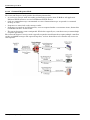
1.5.3. Dual Master (Virtual Peer-to-Peer) - Write Mode
Dual master (virtual peer-to-
peer) - write mode:
• The DeviceMaster and
PLC initiate only write
messages to each other.
• The DeviceMaster
writes received serial
and/or Ethernet device
data directly into PLC
memory with minimal
latency.
• The PLC can write to
serial and/or Ethernet
devices through the DeviceMaster with minimal latency.
• This mode provides the lowest possible Ethernet bandwidth usage and most efficient usage of PLC and
DeviceMaster processing power.
• Only raw/ASCII devices are supported in this mode.
•The DeviceMaster Receive Transfer mode is set to Master and Transmit Transfer mode is set to Slave.
1.5.4. Dual Master (Virtual Peer-to-Peer) - Read Mode (Dual Polling)
Dual master (virtual peer-to-
peer) - read mode (dual
polling):
• This is provided for
programmers who
strongly prefer polling.
• The DeviceMaster and
PLC initiate only read
messages to each other.
• The PLC polls for
received serial and/or
Ethernet device data.
• The DeviceMaster polls
for transmit data to serial and/or Ethernet devices.
• This mode requires the highest possible Ethernet bandwidth usage and provides the least efficient usage
of PLC and DeviceMaster processing power.
• Only raw/ASCII devices are supported in this mode.
• The DeviceMaster Receive Transfer mode is set to Slave and Transmit Transfer mode is set to Master.

DeviceMaster Modbus/TCP User Guide: 2000447 Rev. J Chapter 1. Introduction - 11
Filtering and Data Extraction Functionality (Patent Pending)
1.5.5. Filtering and Data Extraction Functionality (Patent Pending)
The DeviceMaster provides the following filtering and data extraction functionality.
•Filtering:
- String Filtering of up to 128 bytes of raw/ASCII data to both the PLC and/or application.
- RFID filtering of EPCglobal formatted RFID tag data to both the PLC and/or application.
- Barcode filtering of all UPC/EAN formatted barcodes data to both the PLC and/or application.
- Simplifies PLC and application programming tasks.
• Data Extraction:
- RFID data extraction extracts all parameters, such as company code, product code, and serial
numbers, from any or all of the 43 EPCglobal tag formats. It then transfers the data to the PLC and/
or application in a consistent and simple format.
- Barcode data extraction extracts the company, product, and numbering codes from UPC/EAN
formatted barcodes. It then transfers the data to the PLC and/or application in a consistent and
simple format.
- Simplifies PLC and application programming tasks.
• Environment specific support:
- Support for multiple RFID reader tag formats.
- RFID antenna grouping.
- Aging of filtered string/RFID/barcode entries.
- Discarding of unrecognized RFID and barcode messages.
For detailed information about filtering and data extraction, see the DeviceMaster Filtering and Data
Extraction Reference Guide.

12 - Chapter 1. Introduction DeviceMaster Modbus/TCP User Guide: 2000447 Rev. J
Definitions and Terms
1.6. Definitions and Terms
This section describes the Modbus/TCP definitions and terms included in the Modbus/TCP interface and
supported by the DeviceMaster.
1.6.1. Data Type Definitions
The following list defines the available data types.
1.6.2. Glossary
The following list defines terms associated with Modbus/TCP.
Data Type Definition
BYTE Bit String (8-bits)
DINT Signed Double Integer (32-bits)
DWORD Bit String (32-bits)
INT Signed Integer (16-bits)
STRING Character String (1-byte per character)
UDINT Unsigned Double Integer (32-bits)
USINT Unsigned Short Integer (8-bits)
WORD Unsigned Integer (16-bits)
Term Definition
Alias Device ID
The device ID that the original received ID is changed to when an Alias Device ID is
configured.
Device ID
The address of the slave device and the term is identical to Unit Identifier and Slave
Address.
Ethernet Device A device that communicates through an Ethernet TCP/IP connection.
Master Device
A device that transmits Modbus/TCP messages to slave devices and receives the
corresponding responses.
Modbus
An application layer messaging protocol that provides client/server communications
between devices connected on different types of buses.
Modbus Serial The Modbus protocol over a serial connection.
Modbus/ASCII
Modbus Serial in ASCII format. This form of Modbus communication requires two
characters for each byte.
Modbus/RTU Modbus Serial in binary format.
Modbus/TCP
The Modbus protocol over an Ethernet TCP/IP connection, also known as Modbus over
Ethernet.
Raw Serial
Device
A common serial device that communicates over serial ports through plain byte or ASCII
data messages.
Slave Address The address of the slave device. This term is identical to Unit Identifier and Device ID.
Slave Device A device that only responds to Modbus messages.
Socket Port The Ethernet socket port that is used to communicate to an Ethernet device.

DeviceMaster Modbus/TCP User Guide: 2000447 Rev. J Chapter 1. Introduction - 13
Locating the Latest Software and Documents
1.7. Locating the Latest Software and Documents
You can use the links in this table to check for updated software or documentation.
Unit Identifier The address of the slave device and the term is identical to Device ID and Slave Address.
Software and Documentation
PortVision DX
(Windows)
Use PortVision DX to manage Comtrol Ethernet-attached devices to:
• Scan the network for attached devices
• View networked devices in real-time
• Access product-specific network settings configurations
• Assign IP addresses and network settings to one or multiple
devices
• Upload the latest firmware or Bootloader
• Save and load configuration files
• Access DeviceMaster configuration web pages
• Access Telnet/SSH sessions
• Remotely reboot devices
• Download technical documentation
• Enable event logging to assist in monitoring and troubleshooting
• Organize devices into folders and create multiple views
• Enter notes about a folder or device
Modbus/TCP Firmware
This is the application that may or may not have been loaded on the
DeviceMaster depending on the model that was ordered.
You may need to use PortVision DX or the web interface to load the
firmware.
Modbus Hardware Installation
and Configuration Guide
This contains hardware installation, configuration information, and
connector information.
This includes using PortVision DX to configure the IP address and if
necessary, how to update the firmware.
Modbus/TCP Interface
Configuration Quick Start
This document with web interface configuration procedures.
Modbus/TCP User Guide
(This Guide)
The User Guide contains detailed information about the Modbus/TCP
(application) firmware, which includes additional information about
the web configuration interface for Modbus/TCP.
It also discusses the example PLC programs that were installed on
your system and provides a Programming Interface chapter.
Term Definition (Continued)

14 - Chapter 1. Introduction DeviceMaster Modbus/TCP User Guide: 2000447 Rev. J
Modbus/TCP Application Setup
1.8. Modbus/TCP Application Setup
Before you can configure the Modbus/TCP firmware on the DeviceMaster, you must have previously
performed the following steps:
• Install the hardware
• Install PortVision DX
• If necessary, upload the Modbus/TCP firmware using PortVision DX.
Note: Models that have Modbus/TCP loaded on the DeviceMaster are identified in PortVision DX and
the DeviceMaster is labeled accordingly.
• Configure the DeviceMaster IP address using PortVision DX
Note: If necessary, refer to the DeviceMaster MOD or UP Hardware Installation and Configuration Guide
for the above procedures.
Use the following steps to complete the DeviceMaster configuration for Modbus/TCP.
1. Program the Modbus/TCP PLC (refer to the information in Programming Interface
on Page 15).
2. Configure the DeviceMaster serial and Ethernet device interface settings using the Modbus/TCP
Interface Configuration Quick Start. You can use the following chapters if you need additional information
about fields on the web pages.
3. Connect your serial device or devices and make sure all Ethernet devices are attached to the same
Ethernet subnet.
DeviceMaster Filtering and
Data Extraction Reference
Guide
This Guide discusses the data extraction and filtering processes in the
DeviceMaster are designed to off load as much work as possible from
the PLC and/or application and provide a very simple and easy to use
interface for standard RFID and barcode data.
This functionality and interface is designed to save dozens, possibly
hundreds of lines of ladder logic in a typical PLC program.
Software and Documentation

DeviceMaster Modbus/TCP User Guide: 2000447 Rev. J Chapter 2. Programming Interface - 15
Chapter 2. Programming Interface
2.1. Overview
The DeviceMaster provides highly flexible Modbus connectivity.
• Modbus masters supported include Modbus/TCP and Modbus/RTU and Modbus/ASCII serial masters.
• Both serial Modbus/RTU and Modbus/ASCII slave devices are supported.
• All Modbus masters can communicate with all Modbus slave devices.
• The Modbus/RTU and Modbus/ASCII Protocol Interface is defined in (2.4.
Modbus/RTU and Modbus/
ASCII To-Slaves Protocol Interface on Page 27).
The DeviceMaster provides highly advanced raw/ASCII device functionality:
• Both serial and Ethernet TCP/IP devices are supported.
• Modbus interfaces include Modbus/TCP masters, Modbus/TCP slaves, and both Modbus/RTU and
Modbus/ASCII serial masters.
• Up to six Ethernet TCP/IP Application connections per serial or Ethernet TCP/IP device.
• The raw/ASCII interface is defined in (2.2.
Raw Data Interface on Page 17).
You must configure the DeviceMaster through its embedded web pages discussed in the following chapters.
The DeviceMaster uses normal Modbus addressing conventions and provides receive, transmit, and
statistical data.
Appendix A.
Programming the PLC via Concept on Page 105 describes the Concept™ PLC programming
examples provided with the DeviceMaster. It describes how to configure the DeviceMaster for raw serial data
and start running the example programs using the embedded web pages and the example PLC program code.
Note: While the Concept PLC example programs directly apply only to the Schneider Electric Momentum,
Quantum, and Compact PLCs, they can be used as a guide for programming other PLCs.
2.1.1. Modbus Master Requirements
Modbus Masters (Modbus/TCP, Modbus/RTU serial, and Modbus/ASCII) must meet these requirements:
• The Modbus Master must support the corresponding protocol.
• For raw/ASCII data, the Modbus Master must support the Read Holding Registers and Write Multiple
Registers commands or, alternatively, the Read/Write Multiple Registers command.
• The Modbus Master must be able to write enough data in one message to handle the maximum sized
messages required for the serial or Ethernet device.

16 - Chapter 2. Programming Interface DeviceMaster Modbus/TCP User Guide: 2000447 Rev. J
What is Modbus/RTU?
2.1.2. What is Modbus/RTU?
Modbus/RTU is native Modbus in hexadecimal format. These are the base Modbus messages that contain
simple read and write requests. The format is as follows:
Where:
• The terms Master or Client are used to identify the sender of the message.
• The terms Slave or Server are used to identify the devices responding to the message.
Modbus/RTU is used primarily for:
• Serial port connectivity. RS-485 is the most common serial mode, but RS-232 and RS-422 are also widely
used. Commonly used by both Master and Slave devices.
• Ethernet TCP/IP socket connections. This is not the same as Modbus/TCP (please see section on Modbus/
TCP), but does provide a very simple method of interfacing to remote devices. It is used by many
applications and some OPC servers.
Note: This communication method typically is not supported by PLCs.
2.1.3. What is Modbus/ASCII?
Modbus/ASCII is native Modbus in ASCII format. This protocol is used primarily by legacy devices and is no
longer supported as widely as Modbus/RTU.
Like Modbus/RTU, Modbus/ASCII contains the base Modbus messages that contain simple read and write
requests. The differences between Modbus/ASCII and Modbus/RTU are:
1. The message data is sent in ASCII format, so the message length is twice as long. It requires two ASCII
characters for each byte of data.
2. An 8 bit LRC is attached to verify the message instead of a 16 bit CRC. The LRC is also transmitted in
ASCII format.
3. There are defined starting and ending characters to determine a Modbus/ASCII messages.
The format is as follows:
Where:
• The terms Master or Client are used to identify the sender of the message.
• The terms Slave or Server are used to identify the devices responding to the message.
Modbus/ASCII is used primarily for:
• Serial port connectivity. RS-485 is the most common serial mode, but RS-232 and RS-422 are also used.
Used primarily by legacy Slave devices.
• Ethernet TCP/IP socket connections. This is not the same as Modbus/TCP (please see section on Modbus/
TCP), but does provide a very simple method of interfacing to remote devices. It is used by some
applications and some OPC servers.
Note: This communication method typically is not supported by PLCs.

DeviceMaster Modbus/TCP User Guide: 2000447 Rev. J Chapter 2. Programming Interface - 17
What is Modbus/TCP?
2.1.4. What is Modbus/TCP?
Modbus/TCP is an Ethernet network based protocol that contains a Modbus/RTU message, with the exception
of the 2 byte CRC. The Modbus/TCP message contains a header with information designed to provide message
identification and routing information. The format is as follows:
Where:
• The terms Master or Client are used to identify the sender of the message.
• The terms Slave or Server are used to identify the devices responding to the message.
• Modbus TCP messages are typically sent to and received on a defined Ethernet TCP/IP socket of 502.
• Modbus TCP implementations provide more capability, but also require more processing than simpler
Modbus/RTU implementations.
Modbus TCP is used for connecting advanced Ethernet based devices, such as PLCs, HMIs, SCADA Systems,
and most OPC Servers to:
• Other Ethernet devices supporting Modbus TCP.
• Serial Modbus/RTU and/or Modbus/ASCII devices through gateways (such as the DeviceMaster running
the Modbus/TCP or Modbus Router applications).
• Serial or Ethernet TCP/IP raw/ASCII devices (barcode scanners, printers, RFID readers, visions systems,
etc) through a gateway (such as the DeviceMaster running the Modbus/TCP application).
2.2. Raw Data Interface
This subsection contains the following topics:
• Supported Modbus Messages
on Page 17
• Serial Port Raw/ASCII Interface
on Page 18
• Ethernet Device Raw/ASCII Interface
on Page 18
• Receive Data Message
(Raw Data) on Page 21
• Transmit Data Message
(Raw Data) on Page 23
• Sequence Number Messages
(Raw Data) on Page 25
2.2.1. Supported Modbus Messages
DeviceMaster supports the following Modbus messages over Modbus/TCP for raw data transfer.
Note: Your PLC programming software may not allow maximum size serial packets.
Message Type Function Code Maximum Message Size Maximum Serial Packet Size
Read Holding Registers 3 250 BYTEs (125 WORDs) 246 BYTEs (123 WORDs)
Write Multiple Registers 16 (10 hex) 240 BYTEs (120 WORDs) 236 BYTEs (118 WORDs)
Read/Write Multiple
Registers
23 (17 hex) 236 BYTEs (118 WORDs) 232 BYTEs (116 WORDs)

18 - Chapter 2. Programming Interface DeviceMaster Modbus/TCP User Guide: 2000447 Rev. J
Serial Port Raw/ASCII Interface
2.2.2. Serial Port Raw/ASCII Interface
2.2.3. Ethernet Device Raw/ASCII Interface
Serial Port
Raw/ASCII
Addressing
Serial Port 1 Serial Port 2 Serial Port 3 Serial Port 4 Access Rule
Unit ID 255 (FF hex) 255 (FF hex) 255 (FF hex) 255 (FF hex) N/A
Receive Data
Address
1000 (Base 0)
1001 (Base 1)
2000 (Base 0)
2001 (Base 1)
3000 (Base 0)
3001 (Base 1)
4000 (Base 0)
4001 (Base 1)
Read Only
Receive Data
Sequence
Number Address
1256 (Base 0
1257 (Base 1)
2256 (Base 0)
2257 (Base 1)
3256 (Base 0)
3257 (Base 1)
4256 (Base 0)
4257 (Base 1)
Read/Write
Transmit Data
Address
1300 (Base 0)
1301 (Base 1)
2300 (Base 0)
2301 (Base 1)
3300 (Base 0)
3301 (Base 1)
4300 (Base 0)
4301 (Base 1)
Read/Write
Transmit Data
Sequence
Number Address
1556 (Base 0)
1557 (Base 1)
2556 (Base 0)
2557 (Base 1)
3556 (Base 0)
3557 (Base 1)
4556 (Base 0)
4557 (Base 1)
Read/Write
Statistics
Address
1600 (Base 0)
1601 (Base 1)
2600 (Base 0)
2601 (Base 1)
3600 (Base 0)
3601 (Base 1)
4600 (Base 0)
4601 (Base 1)
Read/Write
Socket Port Raw
Data Addressing
Socket Port 1 Socket Port 2 Socket Port 3 Socket Port 4 Access Rule
Unit ID 254 (FE hex) 254 (FE hex) 254 (FE hex) 254 (FE hex) N/A
Receive Data
Address
1000 (Base 0)
1001 (Base 1)
2000 (Base 0)
2001 (Base 1)
3000 (Base 0)
3001 (Base 1)
4000 (Base 0)
4001 (Base 1)
Read Only
Receive Data
Sequence Number
Address
1256 (Base 0
1257 (Base 1)
2256 (Base 0
2257 (Base 1)
3256 (Base 0
3257 (Base 1)
4256 (Base 0
4257 (Base 1)
Read/Write
Transmit Data
Address
1300 (Base 0)
1301 (Base 1)
2300 (Base 0)
2301 (Base 1)
3300 (Base 0)
3301 (Base 1)
4300 (Base 0)
4301 (Base 1)
Read/Write
Transmit Data
Sequence Number
Address
1556 (Base 0)
1557 (Base 1)
2556 (Base 0)
2557 (Base 1)
3556 (Base 0)
3557 (Base 1)
4556 (Base 0)
4557 (Base 1)
Read/Write

DeviceMaster Modbus/TCP User Guide: 2000447 Rev. J Chapter 2. Programming Interface - 19
Raw/ASCII Transfer Modes
2.2.4. Raw/ASCII Transfer Modes
The DeviceMaster supports two different raw/ASCII message transfer modes. The default Data-Stream mode
is the traditional transfer mode that asynchronously transmits messages and returns received data/
responses. The Command/Response mode provides a synchronous transfer mode for sending and returning
responses.
2.2.4.1. Data-Stream Transfer Mode
The Data-Stream transfer mode is the default transfer mode that asynchronously transmits messages from
all Modbus and Application interfaces and returns received data/responses to all Modbus and Application
interfaces. This mode is typically used in installations that utilize only one controller and for receive-only
devices such as barcode scanners, RFID readers, weigh scales, and position encoders.

20 - Chapter 2. Programming Interface DeviceMaster Modbus/TCP User Guide: 2000447 Rev. J
Command/Response Mode
2.2.4.2. Command/Response Mode
The Command/Response mode provides the following functionality:
•A synchronous transfer mode for sending and returning responses from all Modbus and Application
Ethernet TCP/IP interfaces to serial and Ethernet TCP/IP devices.
• Only one command message is transmitted at a time. Command messages are queued if a command
message is active.
• Responses are routed only to the message sender.
• Responses are timed out and old responses, (ones not requested within a certain time frame), destined for
the Modbus interface are discarded.
• The expected response count is configurable. While this is typically one, some devices may return multiple
responses per message.
The Command/Response transfer mode is typically required in installations that require multiple controllers
sending raw/ASCII messages with expected responses, and it is desired that each controller only receive its
own responses.
Page is loading ...
Page is loading ...
Page is loading ...
Page is loading ...
Page is loading ...
Page is loading ...
Page is loading ...
Page is loading ...
Page is loading ...
Page is loading ...
Page is loading ...
Page is loading ...
Page is loading ...
Page is loading ...
Page is loading ...
Page is loading ...
Page is loading ...
Page is loading ...
Page is loading ...
Page is loading ...
Page is loading ...
Page is loading ...
Page is loading ...
Page is loading ...
Page is loading ...
Page is loading ...
Page is loading ...
Page is loading ...
Page is loading ...
Page is loading ...
Page is loading ...
Page is loading ...
Page is loading ...
Page is loading ...
Page is loading ...
Page is loading ...
Page is loading ...
Page is loading ...
Page is loading ...
Page is loading ...
Page is loading ...
Page is loading ...
Page is loading ...
Page is loading ...
Page is loading ...
Page is loading ...
Page is loading ...
Page is loading ...
Page is loading ...
Page is loading ...
Page is loading ...
Page is loading ...
Page is loading ...
Page is loading ...
Page is loading ...
Page is loading ...
Page is loading ...
Page is loading ...
Page is loading ...
Page is loading ...
Page is loading ...
Page is loading ...
Page is loading ...
Page is loading ...
Page is loading ...
Page is loading ...
Page is loading ...
Page is loading ...
Page is loading ...
Page is loading ...
Page is loading ...
Page is loading ...
Page is loading ...
Page is loading ...
Page is loading ...
Page is loading ...
Page is loading ...
Page is loading ...
Page is loading ...
Page is loading ...
Page is loading ...
Page is loading ...
Page is loading ...
Page is loading ...
Page is loading ...
Page is loading ...
Page is loading ...
Page is loading ...
Page is loading ...
Page is loading ...
Page is loading ...
Page is loading ...
Page is loading ...
Page is loading ...
Page is loading ...
Page is loading ...
Page is loading ...
Page is loading ...
Page is loading ...
Page is loading ...
Page is loading ...
Page is loading ...
Page is loading ...
Page is loading ...
Page is loading ...
Page is loading ...
Page is loading ...
Page is loading ...
Page is loading ...
Page is loading ...
Page is loading ...
Page is loading ...
-
 1
1
-
 2
2
-
 3
3
-
 4
4
-
 5
5
-
 6
6
-
 7
7
-
 8
8
-
 9
9
-
 10
10
-
 11
11
-
 12
12
-
 13
13
-
 14
14
-
 15
15
-
 16
16
-
 17
17
-
 18
18
-
 19
19
-
 20
20
-
 21
21
-
 22
22
-
 23
23
-
 24
24
-
 25
25
-
 26
26
-
 27
27
-
 28
28
-
 29
29
-
 30
30
-
 31
31
-
 32
32
-
 33
33
-
 34
34
-
 35
35
-
 36
36
-
 37
37
-
 38
38
-
 39
39
-
 40
40
-
 41
41
-
 42
42
-
 43
43
-
 44
44
-
 45
45
-
 46
46
-
 47
47
-
 48
48
-
 49
49
-
 50
50
-
 51
51
-
 52
52
-
 53
53
-
 54
54
-
 55
55
-
 56
56
-
 57
57
-
 58
58
-
 59
59
-
 60
60
-
 61
61
-
 62
62
-
 63
63
-
 64
64
-
 65
65
-
 66
66
-
 67
67
-
 68
68
-
 69
69
-
 70
70
-
 71
71
-
 72
72
-
 73
73
-
 74
74
-
 75
75
-
 76
76
-
 77
77
-
 78
78
-
 79
79
-
 80
80
-
 81
81
-
 82
82
-
 83
83
-
 84
84
-
 85
85
-
 86
86
-
 87
87
-
 88
88
-
 89
89
-
 90
90
-
 91
91
-
 92
92
-
 93
93
-
 94
94
-
 95
95
-
 96
96
-
 97
97
-
 98
98
-
 99
99
-
 100
100
-
 101
101
-
 102
102
-
 103
103
-
 104
104
-
 105
105
-
 106
106
-
 107
107
-
 108
108
-
 109
109
-
 110
110
-
 111
111
-
 112
112
-
 113
113
-
 114
114
-
 115
115
-
 116
116
-
 117
117
-
 118
118
-
 119
119
-
 120
120
-
 121
121
-
 122
122
-
 123
123
-
 124
124
-
 125
125
-
 126
126
-
 127
127
-
 128
128
-
 129
129
-
 130
130
-
 131
131
-
 132
132


Comtrol UP – Modbus TCP User guide
- Type
- User guide
- This manual is also suitable for
Ask a question and I''ll find the answer in the document
Finding information in a document is now easier with AI
Related papers
-
Comtrol DeviceMaster UP – Modbus TCP User guide
-
Comtrol MOD-2xxx Quick Start
-
-
-
-
-
-
-
-
Other documents
-
ZAPTEC Power Line Communication Installation guide
-
Schneider Electric V334 User manual
-
ABB 620 Series ANSI User manual
-
Pepperl+Fuchs ICDM-RX/MOD-2ST/RJ45-DIN Owner's manual
-
Phoenix ES series User manual
-
-
Weidmuller IE-GW-MB-2TX-1RS232/485 User manual
-
Delta Electronics IFD9507 User manual
-
-
Alien ALR-9800 User manual