Page is loading ...

29 Newtown Business Park, Poole, BH12 3LL, UK • www.alfatronix.com
1 2
3
4
D
T E L: +44 (0) 1202 715 517 • [email protected]
OPERATING & ASSEMBLY
INSTRUCTIONS
PowerVerter-RU
IP65 RUGGEDISED CONVERTERS
C
B
A
SAFETY
PACKING CONTENTS
1 x IP65 RU Power Converter with Flying Lead
1 x Mounting Clip
3 x Screws
3 x Screw Covers
SAFETY
The device must not be exposed to severe mechanical shocks.
The device must not be exposed to extreme temperature, direct sunlight or
vigorous vibration.
Although water-resistant, the device must not be submerged or operated
under water.
During operation the unit can be hot to touch. Therefore it must be positioned
so that during operation it is not readily accessible.
Do not install this device on hot vehicle parts and ensure there is sufficient
space around the device for air circulation and cooling.
The wiring harness should be protected by fuses.
Observe the magnitude and polarity of the input/output voltage when
installing. Incorrect polarity of the output could damage the circuit.
Isolate the circuit before you connect or dismantle the device.
Ensure that the output of the device is not short-circuited.
Never open the device casing and never repair it. The device must be
replaced if it is damaged.
ENGLISH
FEATURES
Safety limiter for heat and current.
Dust, water and impact resistant to IP655.
Utilises GORE-TEX® fabric technology to maintain the water-tight seal whilst
allowing air circulation to prevent the build up of pressure.
LED to indicate when there is output from the unit.
This device complies with the EU directive 2004/108/EC. The type
plate is located on the top of the device.
INFORMATION
WARRANTY
Faulty units returned to us will be repaired or replaced free of charge without
quibble. Usually, repaired faulty items are dispatched within 48 hours of being
received. We have no control over the way the units are installed, the type of
electrical system the units are installed on and the condition of such electrical
systems, neither can we control the kind of load that is applied and the operating
environment on which the units are used. So our guarantee is limited to the
replacing of a failed unit, and we will not pay for any consequential damage.
ENGLISH
TECHNICAL DATA
Note: The above table is for standard units only. All variants are based on these
units, but if you require more information, please contact us.
SÉCURITÉ
CONTENU
1 x IP65 RU Convertisseur avec câble de connexion extérieur
1 x étrier en « T »
3 x vis
3 x cache vis
SECURITE
Tenir l’appareil éloigné de tout choc mécanique.
Ne pas exposer l’appareil à des températures extrêmes, au soleil direct ou à
d’importantes vibrations.
Bien que résistant à l’eau, l’appareil ne doit pas être immergé ou en fonction-
nement sous l’eau.
En cours d’utilisation, l’unité peut être chaude au toucher. Par conséquent,
celle-ci doit être placée de sorte à être difficilement accessible pendant son
fonctionnement.
Ne pas installer l’appareil dans un véhicule à haute température et prenez
garde que l’espace entourant l’appareil soit assez large pour qu’il puisse être
ventilé et se refroidir.
La sangle de connexion doit être protégée par des fusibles.
Veillez à la puissance électrique et la polarité de la tension de sortie lors de
l’installation. Une polarité incorrecte de sortie pourrait entraîner des dom-
mages du circuit.
Isoler le circuit avant de connecter ou de démonter l’appareil.
Assurez-vous que la sortie de l’appareil n’est pas court-circuitée.
Ne jamais ouvrir l’appareil ou tenter de le réparer. L’appareil doit être
remplacé en cas de dommage.
FRANÇAIS
CARACTERISTIQUES
Limiteur de sécurité pour la chaleur et le courant.
IP655 résiste à la poussière, l’eau et les impacts.
Utilisez le tissu GORE TEX® pour maintenir l’étanchéité tout en permettant une
circulation d’air évitant ainsi une pression intérieure excessive.
LED indique lorsque l’appareil est mis sous tension.
L’appareil est conforme aux exigences de la Directive UE
2004/108/CE. La plaquette d’identification se trouve sur le haut
de l’appareil.
INFORMATIONS
GARANTIE
Les unités défectueuses qui nous seront retournées, seront réparées ou
remplacées gratuitement. Habituellement, elles sont réexpédiées dans un délai
de 48 heures après leur réception. Nous n’avons pas de contrôle sur la façon
dont les unités sont installées, le type de système électrique, et l’état de ces
systèmes, de même que nous ne pouvons contrôler le type de charge utilisé et
l’environnement dans lequel les unités sont utilisées. Pour ces raisons, notre
garantie se limite au remplacement d’unités défectueuses et aucune
compensation ne pourra être demandée.
FRANÇAIS
INFORMATIONS TECHNIQUES
Note : Le tableau ci-dessus correspond aux unités standards uniquement. Tous
les produits spéciaux sont basés sur ces unités. Veuillez nous contacter si vous
désirez plus d’informations.
Référence Charge Cont/Int
Tension Nominale
Entrée / Sortie
Dimensions Poids
PV3s-RU 3A/6A non-isolé 24Vdc/12Vdc 86x91x52mm 325g
PV6s-RU 6A/10A non-isolé 24Vdc/12Vdc 108x91x52mm 370g
PV12s-RU 12A/18A non-isolé 24Vdc/12Vdc 146x91x52mm 505g
PV18s-RU 18A/22A non-isolé 24Vdc/12Vdc 186x91x52mm 820g
PV24s-RU 24A/30A non-isolé 24Vdc/12Vdc 186x91x52mm 835g
PV3i-RU 3A/6A isolé 24Vdc/12Vdc 108x91x52mm 390g
PV6i-RU 6A/10A isolé 24Vdc/12Vdc 146x91x52mm 510g
PV12i-RU 12A/18A isolé 24Vdc/12Vdc 186x91x52mm 690g
PV18i-RU 18A/22A isolé 24Vdc/12Vdc 236x91x52mm 1035g
PV24i-RU 24A isolé 24Vdc/12Vdc 236x91x52mm 1050g
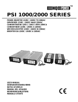
ASSEMBLY
ASSEMBLY
1. Carefully remove the mounting clip from the device using a screwdriver (A).
2. Select a cool and ventilated position to install the device which is not
exposed to direct sunlight and where the device can be assembled vertically
or horizontally.
3. Isolate the power to the wiring before commencing installation.
4. Using the mounting clip as a template, mark the fixing positions.
5. Drill three holes Ø3.5mm for the screws. Before you start, ensure that any
cables or other lines cannot be damaged when drilling.
6. Attach the mounting clip with the screws provided.
7. Cover the screw heads with the protective caps (B).
8. Insert the device in the mounting clip and press down until it clicks into place.
When doing so, make sure that the guide piece on the base of the device fits
properly into the recess on the mounting clip (C).
9. Correctly connect the load.
10. Reconnect the power to the wiring.
THE CONNECTIONS
Isolate the circuit before you connect or disconnect the device. Connect the unit
as detailed below (D).
Brown (1) - Input Positive
Green (2) - Input Negative
White (3) - Output Negative
Red (4) - Output Positive
ENGLISH
FUSING
The input and output wiring must be fused appropriately.
ASSEMBLAGE
ASSEMBLAGE
1. Démonter avec précaution l’étrier en « T » de l’appareil en utilisant un
tournevis (A).
2. Sélectionner un emplacement frais et bien ventilé pour installer l’appareil.
Celui-ci ne doit pas être en contact direct avec la lumière. Montez l’appareil
à l’horizontale ou à la verticale.
3. Isoler le courant du câble avant de commencer l’installation.
4. Utilisez la bride pour marquer la position des orifices.
5. Percez trois trous de 3.5mm. Assurez-vous qu’il n’y ait aucun câble qui
puisse être endommagé lors du perçage.
6. Fixer l’agrafe au moyen des vis fournies.
7. Couvrez les têtes de vis à l’aide des caches de protection (B).
8. Enclenchez l’appareil sur l’agrafe et pressez jusqu’à ce que vous entendiez
le click de fixation. Dans un même temps, assurez-vous que la base de
l’appareil soit positionner de façon à s’insérer correctement dans l’étrier. (C)
9. Connecter la charge.
10. Reconnecter le courant au câble.
LA CONNEXION
Isoler le circuit avant de connecter ou déconnecter l’appareil. Connecter l’unité
comme décrit ci-dessous (D).
Brun (1) – Entrée positive
Vert (2) – Entrée négative
Blanc (3) – Sortie négative
Rouge (4) – Sortie positive
FRANÇAIS
FUSIBLE
Le fusible d’entrée et de sortie doit être connecté de façon appropriée.
Part
Number
Cont/Int Power
Nominal Voltage
Input / Output
Dimensions Weight
PV3s-RU 3A/6A non-isolated 24Vdc/12Vdc 86x91x52mm 325g
PV6s-RU 6A/10A non-isolated 24Vdc/12Vdc 108x91x52mm 370g
PV12s-RU 12A/18A non-isolated 24Vdc/12Vdc 146x91x52mm 505g
PV18s-RU 18A/22A non-isolated 24Vdc/12Vdc 186x91x52mm 820g
PV24s-RU 24A/30A non-isolated 24Vdc/12Vdc 186x91x52mm 835g
PV3i-RU 3A/6A isolated 24Vdc/12Vdc 108x91x52mm 390g
PV6i-RU 6A/10A isolated 24Vdc/12Vdc 146x91x52mm 510g
PV12i-RU 12A/18A isolated 24Vdc/12Vdc 186x91x52mm 690g
PV18i-RU 18A/22A isolated 24Vdc/12Vdc 236x91x52mm 1035g
PV24i-RU 24A isolated 24Vdc/12Vdc 236x91x52mm 1050g
ENGLISH • FRANÇAIS • DEUTSCH • ESPAÑOL

29 Newtown Business Park, Poole, BH12 3LL, UK • www.alfatronix.com
1 2
3
4
D
T E L: +44 (0) 1202 715 517 • [email protected]
OPERATING & ASSEMBLY
INSTRUCTIONS
PowerVerter-RU
IP65 RUGGEDISED CONVERTERS
C
B
A
SEGURIDAD
VOLUMEN DE SUMINISTRO
1 x IP65 RU Convertidor con cable
1 x Clip de montaje
3 x Tornillos
3 x Cubre tornillos
SEGURIDAD
El aparato no debe quedar expuesto a fuertes sacudidas mecánicas.
El aparato no debe quedar expuesto a temperaturas extremas ni a una
radiación directa del sol ni a intensas vibraciones.
Aunque es resistente al agua, el aparato no ha de sumergirse o de utilizarse
debajo del agua.
Durante el funcionamiento la unidad puede estar caliente, por ello ha de
situarse en un lugar de difícil acceso durante su uso.
No lo instale en partes calientes del vehículo y preste atención a que haya
suficiente espacio libre alrededor del aparato para permitir la circulación de
aire y, con ello, la refrigeración.
Proteger las conexiones con fusibles.
Durante el montaje preste atención a la altura y la polaridad de la tensión de
salida. Una polaridad incorrecta o sobretensión pueden perjudicar el circuito
de corriente.
Cortar la corriente antes de conectar el aparato o de desmontarlo.
Asegúrese de que la salida del aparato no esté cortocircuitada.
No está permitido abrir ni reparar el aparato. En caso de avería, deberá
cambiarse.
ESPAÑOL
CARACTERÍSTICAS
Limitador de seguridad para subidas de temperatura y de corriente.
Resistencia al polvo, al agua y a los golpes del IP655.
Utiliza la tecnología GORE-TEX® para mantener el precinto hermético a la
vez que permite la circulación de aire para evitar que aumente la presión.
Indicador LED para indicar cuando hay una salida desde la unidad.
Este aparato cumple los requisites prescritos en la directive de la
UE 2004/108/CE. La placa de identificación se encuentra en la
parte superior del aparato.
INFORMACIÓN
GARANTÍA
Las unidades defectuosas que nos sean enviadas serán reparadas o sustituidas
sin cargo alguno sin objeción. Normalmente, los aparatos defectuosos se
enviarán reparados o sustituidos en un plazo de 48 horas desde su recepción.
No podemos controlar la forma en que se instala una unidad, ni qué tipo de
sistema eléctrico existe ni en qué condición se encuentran, ni tampoco el tipo de
carga que se aplica o el entorno en que se usa. Por ello nuestra garantía se
limita a la sustitución de unidades defectuosas y no pagaremos ningún daño
causado a la unidad.
ESPAÑOL
DATOS TÉCNICOS
Nota: Esta tabla solo hace referencia a unidades estándar Todas las variantes se
basan en estas unidades, pero si necesita más información, no dude en ponerse
en contacto con nosotros.
Número de
pieza
Corriente Cont/Int
Voltaje Nominal
Entrada / Salida
Dimensiones Peso
PV3s-RU 3A/6A sin aislamiento 24Vdc/12Vdc 86x91x52mm 325g
PV6s-RU 6A/10A sin aislamiento 24Vdc/12Vdc 108x91x52mm 370g
PV12s-RU 12A/18A sin aislamiento 24Vdc/12Vdc 146x91x52mm 505g
PV18s-RU 18A/22A sin aislamiento 24Vdc/12Vdc 186x91x52mm 820g
PV24s-RU 24A/30A sin aislamiento 24Vdc/12Vdc 186x91x52mm 835g
PV3i-RU 3A/6A con aislamiento 24Vdc/12Vdc 108x91x52mm 390g
PV6i-RU 6A/10A con aislamiento 24Vdc/12Vdc 146x91x52mm 510g
PV12i-RU 12A/18A con aislamiento 24Vdc/12Vdc 186x91x52mm 690g
PV18i-RU 18A/22A con aislamiento 24Vdc/12Vdc 236x91x52mm 1035g
PV24i-RU 24A con aislamiento 24Vdc/12Vdc 236x91x52mm 1050g
ENSAMBLAJE
ENSAMBLAJE
1. Suelte cuidadosamente el clip de montaje con, por ejemplo, un
destornillador (A).
2. Elija un lugar de montaje que no soporte altas temperaturas y esté ventilado
que no quede expuesto directamente a la radiación solar y en el que el
aparato se pueda montar en posición vertical o en horizontal.
3. Cortar la corriente antes de comenzar la instalación.
4. Utilizando el clip de montaje como plantilla, marcar las posiciones de
fijación.
5. Perfore tres agujeros para los tornillos (Ø3,5mm). Asegúrese de que al
perforar no se pueda dañar ningún cable ni ninguna otra línea.
6. Fije el clip de montaje con los tornillos.
7. Cubra las cabezas de los tornillos con los cubre tornillos (B).
8. Inserte el aparto en el clip de montaje y apriételo hasta que encaje. Al
hacerlo, preste atención a que la pieza guía del borde inferior del aparato
encaje en el hueco del clip de montaje (C).
9. Conectar correctamente las cargas.
10. Volver a conectar a la toma de corriente..
CONEXIONES
Cortar la corriente antes de conectar o desconectar el aparato. Conecte la
unidad como se detalla a continuación (D).
Marrón (1) - Entrada Positiva
Verde (2) - Entrada Negativa
Blanco (3) - Salida Negativa
Rojo (4) - Salida Positiva
ESPAÑOL
FUSIBLES
Los cables de entrada y salida han de conectarse a los fusibles adecuadamente.
SICHERHEIT
INHALT
1 x IP65 RU Spannungswandler mit freiem Kabelanschluss
1 x Montageclip
3 x Schrauben
3 x Schraubabdeckungen
SICHERHEIT
Das Gerät darf nicht extremen mechanischen Schocks, extremen
Temperaturen, direkter Sonneneinstrahlung oder starken Vibrationen
ausgesetzt werden.
Obwohl wasserfest, darf das Gerät nicht unter Wasser betrieben werden oder
ganz untergetaucht werden.
Während des Betriebs kann das Gerät heiß werden, daher muss es so
installiert werden das es nicht leicht zugänglich ist.
Das Gerät nicht auf heißen Fahrzeugteilen installieren und genügend Platz für
Luft Zirkulation und Kühlung gewährleistet.
Den Kabelbaum durch Sicherungen schützen.
Die Stärke und Polarität des Ausgangs sollte bei der Installation beobachtet
werden. Inkorrekte Polarität am Ausgang könnte den Schaltkreis beschädigen.
Den Schaltkreis isolieren bevor das Gerät ein– oder abmontiert wird.
Der Ausgang des Gerätes darf nicht kurzgeschlossen sein.
Sollte das Gerät defekt sein muss es ausgetauscht werden. Das öffnen des
Gehäuses oder die Reparatur des defekten Gerätes ist untersagt.
DEUTSCH
EIGENSCHAFTEN
Übertemperaturschutz und Überlastschutz.
Staub-, wasser– und stoßfest gemäß IP655.
Verwendet GORE-TEX® Gewebetechnologie, diese erlaubt die wasserdichte
Dichtung und dennoch Luft Zirkulation um Druckaufbau vorzubeugen.
Eine LED zeigt den Betrieb des Gerätes an.
Dieses Gerät ist in Erfüllung der EU Direktive 2004/108/EC. Das
Typenschild befindet sich auf der Oberseite des Gerätes.
INFORMATIONEN
GARANTIE
Defekte Geräte die an uns retourniert wurden, reparieren oder ersetzen wir
kostenfrei. Gewöhnlich werden reparierte Geräte innerhalb von 48 Stunden
nach Erhalt versandt. Da wir keinen Einfluss haben auf die Art und Weise wie
die Geräte installiert werden, die Art und Beschaffenheit des elektrischen
Systems, noch die Last der das Gerät ausgesetzt wird, ist unsere Garantie auf
den Austausch des defekten Gerätes begrenzt und bürgt nicht für eventuell
entstandene Schäden.
DEUTSCH
TECHNISCHE DATEN
Anmerkung: Diese Tabelle ist nur für unsere Standard Geräte. Alle Varianten
basieren auf diesen Geräten, sollten Sie weitere Informationen benötigen setzen
Sie sich bitte mit uns Verbindung.
Artikel
Dauer/
Kurzzeitleistung
Nominal Spannung
Eingang / Ausgang
Größe Gewicht
PV3s-RU 3A/6A gemeinsame Masse 24Vdc/12Vdc 86x91x52mm 325g
PV6s-RU 6A/10A gemeinsame Masse 24Vdc/12Vdc 108x91x52mm 370g
PV12s-RU 12A/18A gemeinsame Masse 24Vdc/12Vdc 146x91x52mm 505g
PV18s-RU 18A/22A gemeinsame Masse 24Vdc/12Vdc 186x91x52mm 820g
PV24s-RU 24A/30A gemeinsame Masse 24Vdc/12Vdc 186x91x52mm 835g
PV3i-RU 3A/6A galvanisch getrennt 24Vdc/12Vdc 108x91x52mm 390g
PV6i-RU 6A/10A galvanisch getrennt 24Vdc/12Vdc 146x91x52mm 510g
PV12i-RU 12A/18A galvanisch getrennt 24Vdc/12Vdc 186x91x52mm 690g
PV18i-RU 18A/22A galvanisch getrennt 24Vdc/12Vdc 236x91x52mm 1035g
PV24i-RU 24A galvanisch getrennt 24Vdc/12Vdc 236x91x52mm 1050g
MONTAGE
MONTAGE
1. Entfernen Sie den Montageclip vorsichtig mit einem Schraubenzieher von
dem Gerät (A).
2. Wählen Sie einen kühlen und gut belüfteten Ort zur Installation, welcher
nicht in direkter Sonneneinstrahlung liegt und wo das Gerät horizontal oder
vertikal montiert werden kann.
3. Unterbrechen Sie die Stromversorgung zur Verkabelung bevor Sie mit der
Installation beginnen.
4. Benutzen Sie den Montageclip als Schablone und markieren Sie die
Befestigungspositionen.
5. Bohren Sie die drei Ø3.5mm Löcher für die Schrauben. Stellen Sie sicher das
keine, bereits vorhandenen, Kabel beschädigt werden können.
6. Befestigen Sie den Montageclip mit den enthaltenen Schrauben.
7. Bringen Sie die Schraubenabdeckungen an (B).
8. Führen Sie das Gerät in den Montageclip und drücken Sie es fest bis es
einrastet. Bitte beachten Sie das dass Führungsstück in die Aussparung am
Montageclip passt. (C).
9. Schließen Sie den Verbraucher richtig an.
10. Schließen Sie die Stromversorgung wieder an.
ANSCHLÜSSE
Unterbrechen Sie die Stromversorgung bevor Sie das Gerät anschließen oder
entfernen. Schließen Sie das Gerät wie in der Zeichnung (D) an.
Braun (1) - Eingang Positive
Grün (2) - Eingang Negative
Weiß (3) - Ausgang Negative
Rot (4) - Ausgang Positive
DEUTSCH
SICHERUNGEN
Der Eingang und Ausgang an der Verkabelung muss durch Sicherungen
adäquat geschützt werden.
ENGLISH • FRANÇAIS • DEUTSCH • ESPAÑOL
/