WS Bath Collections 111.597.00.1 User manual
- Type
- User manual

Montageanleitung
Instructions de montage
Istruzioni per il montaggio
Geberit Duofix
Installation
Manual
Installation
Manual

2
© 06-2017
968.075.00.0 (00)
Product Data
Product Specifications
• For installi
ng 2-hole stud mounted wall-hung
washdown water closet fixtures with rear water
i
nlet and waste outlet
• For installation within or in front of drywall panels
• For installation in front of solid walls
• Fits within minimum 3 ½" (90 mm) framing wall
or plumbing chase
• Adjustable for fixture seat heights from 15" to
19" (381 to 483 mm)
• For flush actuator plates Sigma
Features
• Anti-siphon fill val
ve
• Impact resistant high density polyethylene
(HDPE) tank, insulated to prevent condensation
• 16-gauge, powder-coated, structural steel
tubing rated to 880 lbs. (400 kg) without damage
to finished wall or carrier unit
• Includes installation and rough-in materials
Warranty
Limited lifetime warranty on tank and carrier.
10 year warranty on fill valve and flush valve.
One year warranty on actuator plate.
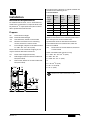
Installation Dimensions
Material Determination
Recommended material for wall surface
construction:
• Gypsum / green board
• Cement board
• Tile backer board
• Ceramic tile surface
Minimum wall material thickness 3/8"
(10 mm)
0–7¾"
FF
3½"
5
1
/2
"
½" NPT
7½"
37⅜"–
41⅜"**
45¼"–
49¼"
26⅜"
19¾"
≥ 12"
11"–15"
1¾"–3½"
⅜"–
2"
3
1
/8
"
For 3½" max.
wall thickness
Vertical drainage only
For optional washlet
electrical outlet box
** assumes a typical seat
thickness of 1" and a distance
from fixture rim to
mounting rod centers of 3"
0–7¾"
FF
7"
typical
2"
3"
2"
For optional washlet
water supply stop
7
1
/8
"/ 9"
0–7¾"
FF
≤ 24½"
15"–19"**
Seated
heigth
37⅜"–41⅜"**
Seated heigth+
22⅜"
For 5½" min.
wall thickness
For RH, LH and
vertical drainage
Geberit Model No. / Flush volume:
• 111.798.00.1 / 1.6/0.8 gpf (6.0/3.0 lpf)
• 111.597.00.1 / 1.28/0.8 gpf (4.8/3.0 lpf)

3
© 06-2017
968.075.00.0 (00)
Installation
Installation Requirements
To install tank and carrier, a 2 x 4" wood frame or
metal frame construction is required. Studs must
be placed 19
3
/4" apart (clearance) where carrier
will be positioned inside the wall.
Prepare
These values are not needed at roughing in, but
may be useful as alternate references:
For convenience, values for a “typical” situation are
included in the following chart:
FOR REFERENCE
** assumes a typical seat thickness of 1" and a
distance from fixture rim to mounting rod centers
of 3". Always refer to the manufacturer
specification sheet for the latest information!
These dimensions are used for later, after the
frame is installed:
Other calculations (for reference only)
FV = FSH - RT - ST + 26
3
/8" (670)
R = FSH - RT - ST
D = FSH - RT - ST - 4" (100)
or
FV = R + 26
3
/8" (670)
H = R + 34 ¼" (870)
D = R - 4" (100)
FF: Finished Floor Height
FSH: Finished Seated Heigth
ST: Seat thickness, based on seat model
RT: Distance from fixture rim to mounting
centers, based on ceramic model
H: Frame Heigth, subject to conditions below:
H = FSH - RT - ST + 34¼" (870)
FV: Flush Valve Height (see below)
R: Rod Heigth, based on ceramic model and
FSH (see below)
D: Drain outlet, based on ceramic model and
FSH (see below)
19¾"
0–7¾"
FF
FSH
R
FV
H
D
RT
ST
Finished
Seat
Height
(FSH)
Frame
Height
(H)
Flush
Valve
Height
(FV)
Rod
Height
(R)
Drain
Outlet
Height
(D)
15 45 ¼
37
3
/8
11 7
16 46 ¼
38
3
/8
12 8
17 47 ¼
39
3
/8
13 9
18 48 ¼
40
3
/8
14 10
19 49 ¼
41
3
/8
15 11
RC: Rod Center-to-Center Distance, based on
ceramicmodel
All dimensions Above Finished Floor (AFF)

4
© 06-2017
968.075.00.0 (00)
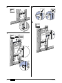
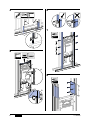
Installation Overview
Duofix Element in Holzständerwand montieren
1
04
07
RH, LH or vertical drainage runs allowed with
5 ½" minimum wall thickness.
Vertical drainage run only for 3 ½" maximum
walls.
19¾"
FF
min. 5½" wall
or chase
A
B
13 mm
B
B
A
H

5
© 06-2017
968.075.00.0 (00)
2
3
4
5
H
FF
B
A
B
A
A
B
ø ⅜''

6
© 06-2017
968.075.00.0 (00)
6
7
8
9
13 mm
A
B
B
13 mm
A
B
H
10 mm

7
© 06-2017
968.075.00.0 (00)
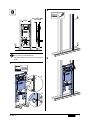
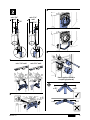
Duofix Element in Trockenbauwand montieren
1
2
3
RH, LH or vertical drainage runs allowed with
5 ½" minimum wall thickness.
Vertical drainage run only for 3 ½" maximum
walls.
19¾"
FF
min. 5½" wall
or chase
A
B
13 mm
B
B
A
H
H
FF

8
© 06-2017
968.075.00.0 (00)
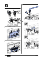
4
5
6
7
8
ø ⅜''
13 mm
B
A
B
13 mm
A
H
B
12"
12"
PH 3
12"
PH 3

9
© 06-2017
968.075.00.0 (00)
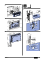
Abgangsbogen montieren
1
2
3
4
5
1¾"
min. 3½"
wall
3½"
min. 5½"
wall
3½"
1¾"
min. 3½" wall
min. 5½" wall
Use supplied flexible
coupling (optional)
≥ 45° ≥ 45°
≤ 45°
≤ 45°

10
© 06-2017
968.075.00.0 (00)
Wasseranschluss montieren
1
2
3
4
5
1 2
3
¾"
NPT ½"
elbow
½"
½"
1
2
3
3
2
1

11
© 06-2017
968.075.00.0 (00)
6
7
8
Stromanschluss bei Duofix Element vorbereiten
`
1¾
"
5½"
3⅛"
7⅛"
/ 9"
ø 1½
"
ø 3
"
4"
1⅜"
3½
"
ø 5½
"
ø 1½
"
ø 3
"
4"
1⅜"
7⅛"
/ 9"

Geberit International AG, Schachenstrasse 77, CH-8645 Jona
T +41 55 221 63 00
F +41 55 221 63 16
➔ www.geberit.com
12
© 06-2017
968.075.00.0 (00)
Geberit , 2100 Clearwater Drive, Des Plaines, IL 60018-5999
Phone: (847) 803 5000
Fax: 847/803-5454
For Technical Assistance: 800 / TEC-TRUE (800-832-8783)
➔ www.geberit.us
-
 1
1
-
 2
2
-
 3
3
-
 4
4
-
 5
5
-
 6
6
-
 7
7
-
 8
8
-
 9
9
-
 10
10
-
 11
11
-
 12
12


WS Bath Collections 111.597.00.1 User manual
- Type
- User manual
Ask a question and I''ll find the answer in the document
Finding information in a document is now easier with AI
Other documents
-
Geberit 1805752 Installation guide
-
-
-
-
-
Geberit 111060001 User manual
-
 Giles FSH-2A-99 User manual
-
 Giles FSH-6 User manual
-
-

