Page is loading ...

A
RMOR DOO
R
TM
INSTALLATION OF WELDED FRAMES
P
R
I
O
R
TO
INSTALLATION
The installer shall perform the following prior to
installation:
The area of floor on which the frame is to be
installed and the path of the door swing shall be
checked for flatness and levelness. Permissible tol-
erance is +/- 1/16 in. (1.5mm). If the floor exceeds
this, it is the general contractor’s responsibility to
correct the area that is out of tolerance before the
frame is installed.
Frame shall be checked for correct size, swing, fire
rating and opening number.
Remove temporary steel sprea
ders.
Spreaders can
typically
be removed with cold chisel and hammer.
With frame standing on concrete,
position cold
chisel at w
eld joint of spreader and jamb and str
ik
e
chisel with hammer
.
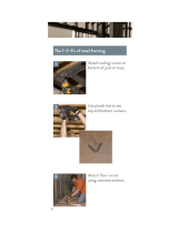
TYPICAL INSTALLATION PROCEDURES
Position frame in the correct location.
Brace the
frame as shown, Figure 1. Do not brace in the direc-
tion of intended wall.
FIGURE
1
FRAME BRACING
With frame in position, install the temporary wood
spreaders.
The wood spreader, Figure 2, must be
square and no less than 1 in.
(25 mm) thick. Correct
length is the door opening width between the jambs
at the header. Cut clearance notches for frame
stops. Spreader must be nearly as wide as frame
depth for proper installation. Install a spreader at
the bottom of the frame and a second wood spread-
er at the mid or strike point to maintain a proper
door opening and to prevent bowing of the jambs,
Figure 3. Clamp or wire spreaders to frame to hold
spreaders in place until the frames are set perma-
nently in the wall.
2"x4" BRACE
SUPPORT BRACE
AT FLOOR
FIGURE 2
WOOD SPREADER
FIGURE 3
SPREADER LOCATION
DOOR OPENING AT HEADER
FRAME
DEPTH
SPREADER
SPREADERS

A
RMOR DOO
R
TM
INSTALLATION OF WELDED FRAMES
The installation contractor shall have a carpenter
level and builder’s square.
Level the head by posi-
tioning the level to the head door rabbet, Figure 4. If
necessary, adjust for high spots in floor by shim-
ming under the jamb floor anchor, Figure 7.
Equalize them through an adjustable floor anchor, if
specified, Figure 13b. Note, for labeled openings
the maximum floor clearance is 3/4 in. (19mm).
FIGURE
4
LEVELING THE HEAD
With carpenter level check the frame for plumbness
and alignment: For plumbness, position level
against both hinge and strike jambs in the rabbet.
For alignment; Position level against both hinge and
strike jambs on the stop, adjust as required, Figure 5.
FIGURE
5
PLUMBING AND ALIGNMENT
SCETION A-A
ALIGNMENT
LEVEL
PLUMB
A
LEVEL
A
LEVE
L
LEVE
L
Once the installer has ensured that the frame is in
the correct position, anchor the jamb to the floor.
Floor Anchors: The fixed floor anchor is welded to
the base of the jamb, typically secured to the floor
by mechanical fasteners, providing solid anchorage
for the base of each jamb, Figure 7. Shimming
must be used if the floor is not level. This type of
anchor is not used in existing masonry, preframed
stud walls or slip-on dry-wall frames, but may be
provided.
At prepared openings (existing masonry or con-
crete) an additional expansion anchor reinforce-
ment is provided. With pre-framed stud walls or
completed drywall openings an additional base
anchor is included. In both instances these anchors
are located as close to the bottom of the jamb as is
practical.
FIGURE
7
FIXED FLOOR ANCHOR
With builder’s square, check frame for squareness.
Position square against jamb and head at door rab-
bet, adjust as required, Figure 6.
FIGURE
6
SQUARENESS

A
RMOR DOO
R
TM
INSTALLATION OF WELDED FRAMES
1. MASONRY WALLS
Installation of a hollow metal frame in masonry, Fig-
ure 8. Refer to HMMA 820 Hollow Metal Frames
for additional anchorage methods.
SPREADERS
90? 90?
FIGURE 10
WIRE LOOP ANCHOR
FIGURE 11
WIRE LOOP ANCHOR
FIGURE 8
MASONRY WALL
Wire Loop anchor, Figure 10, function similar to
the metal strap anchor but are set loose inside
frame returns as wall is laid up.
As wall is laid up, locate the anchors at the hinges
in the hinge jamb and at a corresponding position in
the strike jamb, Figure 11.
Continually check squareness, plumbness, alignment,
and twist in the frame as wall progresses.

A
RMOR DOO
R
TM
INSTALLATION OF WELDED FRAMES
2. STEEL STUD WALLS
Installation
of a hollow metal frame in steel stud
wall, Figure 11.
Refer to HMMA 820 Hollow Metal
Frames for additional anchorage methods.
FIGURE 13
DRYWALL STUD ANCHOR
INSTALLATION ON FRAME
SPREADERS
90
?
JAMB
STUDS
CEILING RUNNER
HEADER STUD
FLOOD RUNNER
90
?
Combination wood / steel stud anchors, Figure 12
& 13
, are welded (optional) or friction fit inside the
jamb. Additional horizontal straps allows fastening
to the face of the stud in lieu of through the throat.
Typically used when the steel stud wall is
assembled prior to setting the frame.
Position the vertical steel studs in the frame throat
opening in accordance with architect’s details.
Attach the vertical steel studs to floor and ceiling
runners and fasten to the steel stud anchors with
mechanical fasteners.
FIGURE 12
DR
YWALL STUD ANCHOR
FIGURE
11
STEEL STUD
WALL

A
RMOR DOO
R
TM
PAINTING HOLLOW METAL PRODUCTS
Hollow Metal doors, frames, and related products
are fabricated from hot-rolled, cold-rolled, zinc-
coated, or stainless steel. Stainless is typically not
painted and therefore not referred to in this tech
note. Hot and cold-rolled steel are supplied either
dry or oiled and require treatment prior to painting.
Zinc coated steel is either galvannealed or
galvanized. Galvannealed steel is manufactured
suitable for immediate painting without further
treatment other than normal cleaning. Galvanized
steel requires treatment prior to painting. Refer to
HMMA-802 “Manufacturing of Hollow Metal Doors
and Frames” for more information.
Breakdown of the primer adhesion can be caused by
incompatibility with the finish coat of paint resulting in
the same conditions as listed above. Care must be
taken to ensure compatibility of primer and any top
coat. A small area test is always recommended to
verify compatibility and adhesion. In some instances,
a barrier coast between primer and top coast is
necessary. Consult finish paint manufacturer’s
instructions.
Hollow Metal products must be stored in a manner to
prevent exposure to adverse environmental
elements. Refer to HMMA-840, “Guide Specification
for Installation and Storage of Hollow Metal Doors
and Frames” for more information. Primer protects
the uncoated base metal and provides the bonding
agent required for the finished paint. It is very
important that the primer is protected and cleaned
prior to the application of the finish coat of paint.
Primer manufacturers advise that the primer receive
a finish coat within 30 days of delivery.
Exposure to elements, such as high humidity, salt
air, snow, rain, damp wrappings, etc..., without
proper protection and air circulation, allows moisture
to be absorbed by the primer. Once this occurs, with
the presence of oxygen, an electrolytic action
follows. Moisture travels between primer and the
metal surfaces in a capillary action, deteriorating
primer adhesion. Eventually this can result in water
stains, rusting, flaking, lifting, or peeling. When paint
flakes, lifts, or peels, rusting is not always evident.
Typically these areas have not been in constant
contact with the elements, but moisture has traveled
under the primer.
Different paint problems have different solutions.
Depending on the severity of the problems, sanding,
sanding to bare metal, cleaning to remove
contaminants, and re-priming can be necessary.
The selection of paint is also a consideration.
Manufacturing marks are not always visible with a fiat
low gloss primer but can appear after a gloss finish
coat is applied. The use of high gloss paint will
increase the show through tendencies and is not
recommended. A maximum paint gloss rating of 20%
reflectance, measured using a 60 degree gloss
meter, would be the standard recommended. Select a
commercial direct to metal, (DTM) quality paint.
It is extremely important to follow the finish paint
manufacturer’s instructions. It is important to avoid
painting in extremely hot, cold, or damp weather.
Ensure material being painted is clean and dry. Prior
to finish painting lightly sand primed surfaces with
fine grit sand paper or emery cloth.
/