Installation Instructions
Built-In Dishwasher
If you have questions, call 800.GE.CARES (800.432.2737) or visit our Website at: GEAppliances.com.
In Canada, please call 1.800.561.3344 or visit www.geappliances.ca
READ CAREFULLY
KEEP THESE INSTRUCTIONS
FOR YOUR SAFETY
Read and observe all WARNINGS and CAUTIONS shown
throughout these instructions. While performing installations
described in this booklet, gloves, safety glasses or goggles
should be worn.
IMPORTANT – Observe all governing codes and
ordinances.
• Note to Installer – Be sure to leave these instructions for the
consumer’s and local inspector’s use.
• Note to Consumer – Keep these instructions with your
Owner’s Manual for future reference.
• Skill Level – Installation of this dishwasher requires
basic mechanical, electrical and plumbing skills. Proper
installation is the responsibility of the installer. Product
failure due to improper installation is not covered under
the GE Appliance Warranty. See warranty information.
• Completion Time – 1 to 3 Hours. New installations require
more time than replacement installations.
IMPORTANT – The dishwasher MUST be installed to
allow for future removal from the enclosure if service is required.
Care should be exercised when the appliance is installed or removed,
to reduce the likelihood of damage to the power supply cord.
If you received a damaged dishwasher, you should immediately
contact your dealer or builder.
Optional Accessories – See the Owner’s Manual for available
custom panel kits.
Your dishwasher is a water heating appliance.
BEFORE YOU BEGIN
Read these instructions completely and carefully.
31-31560 02-16 GE
Printed in the United States
• 7RUHGXFHWKHULVNRIHOHFWULFVKRFN¿UHRULQMXU\WR
persons, the installer must ensure that the dishwasher is
completely enclosed at the time of installation.
• FOR PERSONAL SAFETY: Remove house fuse or open
circuit breaker before beginning installation. Do not use an
extension cord or adapter plug with this appliance.
• The improper connection of the equipment grounding
conductor can result in a risk of electric shock. Check with
DTXDOL¿HGHOHFWULFLDQRUVHUYLFHUHSUHVHQWDWLYHLI\RXDUH
in doubt that the appliance is properly grounded.
• If house wiring is not 2-wire with ground, a ground
must be provided by the installer. When house wiring
is aluminum, be sure to use UL-Listed anti-oxidant
compound and aluminum-to-copper connectors.
Do not remove wood base until you are ready to install the
dishwasher. The dishwasher will tip over when the door is
opened if base is removed.
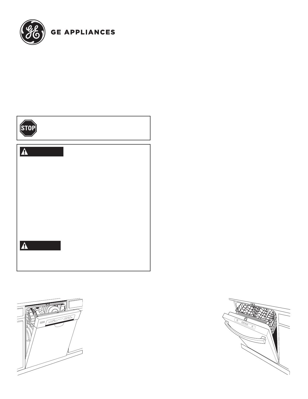
CHECK THE FOLLOWING
Tub trim does not interfere with the door
Dishwasher is square and level at both the top and bottom
of the cabinet opening, with no twisting or distortion of the
tub or door
$OOOHJVRIWKHGLVKZDVKHUDUH¿UPO\LQFRQWDFWZLWKWKH
ÀRRU
Drain hose is not pinched between the dishwasher and
DGMDFHQWFDELQHWVRUZDOOV
7XEWULPLVIXOO\VHDWHGRQWKHWXEÀDQJH
CAUTION
WARNING