Miller DIALARC 25 Owner's manual
- Category
- Welding System
- Type
- Owner's manual
This manual is also suitable for

Dialarc 250/250P AC/DC
Processes
Description
R
Stick (SMAW) Welding
Arc Welding Power Source
OM-321 202730
April 2001
Visit our website at
www.MillerWelds.com

Miller Electric manufactures a full line
of welders and welding related equipment.
For information on other quality Miller
products, contact your local Miller distributor
to receive the latest full line catalog or
individual catalog sheets. To locate your nearest
distributor or service agency call 1-800-4-A-Miller,
or visit us at www.MillerWelds.com on the web.
Thank you and congratulations on choosing Miller.
Now you can get the job done and get it done right. We
know you don’t have time to do it any other way.
That’s why when Niels Miller first started building arc
welders in 1929, he made sure his products offered
long-lasting value and superior quality. Like you, his
customers couldn’t afford anything less. Miller
products had to be more than the best they could be.
They had to be the best you could buy.
Today, the people that build and sell Miller products continue the
tradition. They’re just as committed to providing equipment and service
that meets the high standards of quality and value established in 1929.
This Owner’s Manual is designed to help you get the most out of your
Miller products. Please take time to read the Safety precautions. They
will help you protect yourself against potential hazards on the worksite.
We’ve made installation and operation quick
and easy. With Miller you can count on years
of reliable service with proper maintenance.
And if for some reason the unit needs repair,
there’s a Troubleshooting section that will
help you figure out what the problem is. The
parts list will then help you to decide which
exact part you may need to fix the problem.
Warranty and service information for your
particular model are also provided.
Miller is the first welding
equipment manufacturer in
the U.S.A. to be registered to
the ISO 9001 Quality System
Standard.
Working as hard as you do
– every power source from
Miller is backed by the most
hassle-free warranty in the
business.
From Miller to You
Miller offers a Technical
Manual which provides
more detailed service and
parts information for your
unit. To obtain a Technical
Manual, contact your local
distributor. Your distributor
can also supply you with
Welding Process Manuals
such as SMAW, GTAW,
GMAW, and GMAW-P.

The following terms are
used interchangeably
throughout this manual:
TIG = GTAW
Stick = SMAW
TABLE OF CONTENTS
SECTION 1 – SAFETY PRECAUTIONS - READ BEFORE USING 1. . . . . . . . . . . . . . . . . . . . . . . . . . . .
1-1. Symbol Usage 1. . . . . . . . . . . . . . . . . . . . . . . . . . . . . . . . . . . . . . . . . . . . . . . . . . . . . . . . . . . . . . . .
1-2. Arc Welding Hazards 1. . . . . . . . . . . . . . . . . . . . . . . . . . . . . . . . . . . . . . . . . . . . . . . . . . . . . . . . . .
1-3. Additional Symbols For Installation, Operation, And Maintenance 3. . . . . . . . . . . . . . . . . . . . .
1-4. Principal Safety Standards 3. . . . . . . . . . . . . . . . . . . . . . . . . . . . . . . . . . . . . . . . . . . . . . . . . . . . .
1-5. EMF Information 4. . . . . . . . . . . . . . . . . . . . . . . . . . . . . . . . . . . . . . . . . . . . . . . . . . . . . . . . . . . . . .
SECTION 1 – CONSIGNES DE SECURITE – LIRE AVANT UTILISATION 5. . . . . . . . . . . . . . . . . . . . .
1-1. Signification des symboles 5. . . . . . . . . . . . . . . . . . . . . . . . . . . . . . . . . . . . . . . . . . . . . . . . . . . . .
1-2. Dangers relatifs au soudage à l’arc 5. . . . . . . . . . . . . . . . . . . . . . . . . . . . . . . . . . . . . . . . . . . . . .
1-3. Dangers supplémentaires en relation avec l’installation, le fonctionnement
et la maintenance 7. . . . . . . . . . . . . . . . . . . . . . . . . . . . . . . . . . . . . . . . . . . . . . . . . . . . . . . . . . . . .
1-4. Principales normes de sécurité 8. . . . . . . . . . . . . . . . . . . . . . . . . . . . . . . . . . . . . . . . . . . . . . . . . .
1-5. Information sur les champs électromagnétiques 8. . . . . . . . . . . . . . . . . . . . . . . . . . . . . . . . . . . .
SECTION 2 – INSTALLATION 9. . . . . . . . . . . . . . . . . . . . . . . . . . . . . . . . . . . . . . . . . . . . . . . . . . . . . . . . . . .
2-1. Specifications 9. . . . . . . . . . . . . . . . . . . . . . . . . . . . . . . . . . . . . . . . . . . . . . . . . . . . . . . . . . . . . . . .
2-2. Duty Cycle And Overheating 10. . . . . . . . . . . . . . . . . . . . . . . . . . . . . . . . . . . . . . . . . . . . . . . . . . . .
2-3. Volt-Ampere Curves 10. . . . . . . . . . . . . . . . . . . . . . . . . . . . . . . . . . . . . . . . . . . . . . . . . . . . . . . . . . .
2-4. Dimensions And Weights 11. . . . . . . . . . . . . . . . . . . . . . . . . . . . . . . . . . . . . . . . . . . . . . . . . . . . . . .
2-5. Selecting A Location 11. . . . . . . . . . . . . . . . . . . . . . . . . . . . . . . . . . . . . . . . . . . . . . . . . . . . . . . . . . .
2-6. Weld Cable Sizes 12. . . . . . . . . . . . . . . . . . . . . . . . . . . . . . . . . . . . . . . . . . . . . . . . . . . . . . . . . . . . .
2-7. Connecting To Weld Output Terminals 12. . . . . . . . . . . . . . . . . . . . . . . . . . . . . . . . . . . . . . . . . . . .
2-8. Electrical Service Guide 13. . . . . . . . . . . . . . . . . . . . . . . . . . . . . . . . . . . . . . . . . . . . . . . . . . . . . . . .
2-9. Placing Jumper Links And Connecting Input Power 14. . . . . . . . . . . . . . . . . . . . . . . . . . . . . . . . .
SECTION 3 – OPERATION 15. . . . . . . . . . . . . . . . . . . . . . . . . . . . . . . . . . . . . . . . . . . . . . . . . . . . . . . . . . . . .
3-1. Controls 15. . . . . . . . . . . . . . . . . . . . . . . . . . . . . . . . . . . . . . . . . . . . . . . . . . . . . . . . . . . . . . . . . . . . .
SECTION 4 – MAINTENANCE & TROUBLESHOOTING 16. . . . . . . . . . . . . . . . . . . . . . . . . . . . . . . . . . . .
4-1. Routine Maintenance 16. . . . . . . . . . . . . . . . . . . . . . . . . . . . . . . . . . . . . . . . . . . . . . . . . . . . . . . . . .
4-2. Troubleshooting 16. . . . . . . . . . . . . . . . . . . . . . . . . . . . . . . . . . . . . . . . . . . . . . . . . . . . . . . . . . . . . .
SECTION 5 – ELECTRICAL DIAGRAMS 17. . . . . . . . . . . . . . . . . . . . . . . . . . . . . . . . . . . . . . . . . . . . . . . . .
SECTION 6 – PARTS LIST 18. . . . . . . . . . . . . . . . . . . . . . . . . . . . . . . . . . . . . . . . . . . . . . . . . . . . . . . . . . . . . .
OPTIONS AND ACCESSORIES
WARRANTY
WARNING
This product, when used
for welding or cutting,
produces fumes or
gases which contain
chemicals known to the
State of California to
cause birth defects and,
in some cases, cancer.
(California Health &
Safety Code Section
25249.5 et seq.)
OM-321
Page is loading ...

OM-321 Page 1
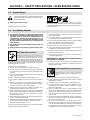
SECTION 1 – SAFETY PRECAUTIONS - READ BEFORE USING
som _nd_4/98
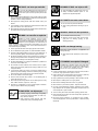
1-1. Symbol Usage
Means Warning! Watch Out! There are possible hazards
with this procedure! The possible hazards are shown in
the adjoining symbols.
Y Marks a special safety message.
. Means “Note”; not safety related.
This group of symbols means Warning! Watch Out! possible
ELECTRIC SHOCK, MOVING PARTS, and HOT PARTS hazards.
Consult symbols and related instructions below for necessary actions
to avoid the hazards.
1-2. Arc Welding Hazards
Y The symbols shown below are used throughout this manual to
call attention to and identify possible hazards. When you see
the symbol, watch out, and follow the related instructions to
avoid the hazard. The safety information given below is only
a summary of the more complete safety information found in
the Safety Standards listed in Section 1-4. Read and follow all
Safety Standards.
Y Only qualified persons should install, operate, maintain, and
repair this unit.
Y During operation, keep everybody, especially children, away.
ELECTRIC SHOCK can kill.
Touching live electrical parts can cause fatal shocks
or severe burns. The electrode and work circuit is
electrically live whenever the output is on. The input
power circuit and machine internal circuits are also
live when power is on. In semiautomatic or automatic wire welding, the
wire, wire reel, drive roll housing, and all metal parts touching the
welding wire are electrically live. Incorrectly installed or improperly
grounded equipment is a hazard.
D Do not touch live electrical parts.
D Wear dry, hole-free insulating gloves and body protection.
D Insulate yourself from work and ground using dry insulating mats
or covers big enough to prevent any physical contact with the work
or ground.
D Do not use AC output in damp areas, if movement is confined, or if
there is a danger of falling.
D Use AC output ONLY if required for the welding process.
D If AC output is required, use remote output control if present on
unit.
D Disconnect input power or stop engine before installing or
servicing this equipment. Lockout/tagout input power according to
OSHA 29 CFR 1910.147 (see Safety Standards).
D Properly install and ground this equipment according to its
Owner’s Manual and national, state, and local codes.
D Always verify the supply ground – check and be sure that input
power cord ground wire is properly connected to ground terminal in
disconnect box or that cord plug is connected to a properly
grounded receptacle outlet.
D When making input connections, attach proper grounding conduc-
tor first – double-check connections.
D Frequently inspect input power cord for damage or bare wiring –
replace cord immediately if damaged – bare wiring can kill.
D Turn off all equipment when not in use.
D Do not use worn, damaged, undersized, or poorly spliced cables.
D Do not drape cables over your body.
D If earth grounding of the workpiece is required, ground it directly
with a separate cable.
D Do not touch electrode if you are in contact with the work, ground,
or another electrode from a different machine.
D Use only well-maintained equipment. Repair or replace damaged
parts at once. Maintain unit according to manual.
D Wear a safety harness if working above floor level.
D Keep all panels and covers securely in place.
D Clamp work cable with good metal-to-metal contact to workpiece
or worktable as near the weld as practical.
D Insulate work clamp when not connected to workpiece to prevent
contact with any metal object.
D Do not connect more than one electrode or work cable to any
single weld output terminal.
SIGNIFICANT DC VOLTAGE exists after removal of
input power on inverters.
D Turn Off inverter, disconnect input power, and discharge input
capacitors according to instructions in Maintenance Section
before touching any parts.
Welding produces fumes and gases. Breathing
these fumes and gases can be hazardous to your
health.
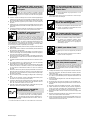
FUMES AND GASES can be hazardous.
D Keep your head out of the fumes. Do not breathe the fumes.
D If inside, ventilate the area and/or use exhaust at the arc to remove
welding fumes and gases.
D If ventilation is poor, use an approved air-supplied respirator.
D Read the Material Safety Data Sheets (MSDSs) and the
manufacturer’s instructions for metals, consumables, coatings,
cleaners, and degreasers.
D Work in a confined space only if it is well ventilated, or while
wearing an air-supplied respirator. Always have a trained watch-
person nearby. Welding fumes and gases can displace air and
lower the oxygen level causing injury or death. Be sure the breath-
ing air is safe.
D Do not weld in locations near degreasing, cleaning, or spraying op-
erations. The heat and rays of the arc can react with vapors to form
highly toxic and irritating gases.
D Do not weld on coated metals, such as galvanized, lead, or
cadmium plated steel, unless the coating is removed from the weld
area, the area is well ventilated, and if necessary, while wearing an
air-supplied respirator. The coatings and any metals containing
these elements can give off toxic fumes if welded.

OM-321 Page 2
Arc rays from the welding process produce intense
visible and invisible (ultraviolet and infrared) rays
that can burn eyes and skin. Sparks fly off from the
weld.
ARC RAYS can burn eyes and skin.
D Wear a welding helmet fitted with a proper shade of filter to protect
your face and eyes when welding or watching (see ANSI Z49.1
and Z87.1 listed in Safety Standards).
D Wear approved safety glasses with side shields under your
helmet.
D Use protective screens or barriers to protect others from flash and
glare; warn others not to watch the arc.
D Wear protective clothing made from durable, flame-resistant mate-
rial (leather and wool) and foot protection.
Welding on closed containers, such as tanks,
drums, or pipes, can cause them to blow up. Sparks
can fly off from the welding arc. The flying sparks, hot
workpiece, and hot equipment can cause fires and
burns. Accidental contact of electrode to metal objects can cause
sparks, explosion, overheating, or fire. Check and be sure the area is
safe before doing any welding.
WELDING can cause fire or explosion.
D Protect yourself and others from flying sparks and hot metal.
D Do not weld where flying sparks can strike flammable material.
D Remove all flammables within 35 ft (10.7 m) of the welding arc. If
this is not possible, tightly cover them with approved covers.
D Be alert that welding sparks and hot materials from welding can
easily go through small cracks and openings to adjacent areas.
D Watch for fire, and keep a fire extinguisher nearby.
D Be aware that welding on a ceiling, floor, bulkhead, or partition can
cause fire on the hidden side.
D Do not weld on closed containers such as tanks, drums, or pipes,
unless they are properly prepared according to AWS F4.1 (see
Safety Standards).
D Connect work cable to the work as close to the welding area as
practical to prevent welding current from traveling long, possibly
unknown paths and causing electric shock and fire hazards.
D Do not use welder to thaw frozen pipes.
D Remove stick electrode from holder or cut off welding wire at
contact tip when not in use.
D Wear oil-free protective garments such as leather gloves, heavy
shirt, cuffless trousers, high shoes, and a cap.
D Remove any combustibles, such as a butane lighter or matches,
from your person before doing any welding.
FLYING METAL can injure eyes.
D Welding, chipping, wire brushing, and grinding
cause sparks and flying metal. As welds cool,
they can throw off slag.
D Wear approved safety glasses with side
shields even under your welding helmet.
BUILDUP OF GAS can injure or kill.
D Shut off shielding gas supply when not in use.
D Always ventilate confined spaces or use
approved air-supplied respirator.
HOT PARTS can cause severe burns.
D Do not touch hot parts bare handed.
D Allow cooling period before working on gun or
torch.
MAGNETIC FIELDS can affect pacemakers.
D Pacemaker wearers keep away.
D Wearers should consult their doctor before
going near arc welding, gouging, or spot
welding operations.
NOISE can damage hearing.
Noise from some processes or equipment can
damage hearing.
D Wear approved ear protection if noise level is
high.
Shielding gas cylinders contain gas under high
pressure. If damaged, a cylinder can explode. Since
gas cylinders are normally part of the welding
process, be sure to treat them carefully.
CYLINDERS can explode if damaged.
D Protect compressed gas cylinders from excessive heat, mechani-
cal shocks, slag, open flames, sparks, and arcs.
D Install cylinders in an upright position by securing to a stationary
support or cylinder rack to prevent falling or tipping.
D Keep cylinders away from any welding or other electrical circuits.
D Never drape a welding torch over a gas cylinder.
D Never allow a welding electrode to touch any cylinder.
D Never weld on a pressurized cylinder – explosion will result.
D Use only correct shielding gas cylinders, regulators, hoses, and fit-
tings designed for the specific application; maintain them and
associated parts in good condition.
D Turn face away from valve outlet when opening cylinder valve.
D Keep protective cap in place over valve except when cylinder is in
use or connected for use.
D Read and follow instructions on compressed gas cylinders,
associated equipment, and CGA publication P-1 listed in Safety
Standards.

OM-321 Page 3
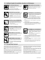
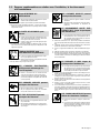
1-3. Additional Symbols For Installation, Operation, And Maintenance
FIRE OR EXPLOSION hazard.
D Do not install or place unit on, over, or near
combustible surfaces.
D Do not install unit near flammables.
D Do not overload building wiring – be sure power supply system is
properly sized, rated, and protected to handle this unit.
FALLING UNIT can cause injury.
D Use lifting eye to lift unit only, NOT running
gear, gas cylinders, or any other accessories.
D Use equipment of adequate capacity to lift and
support unit.
D If using lift forks to move unit, be sure forks are
long enough to extend beyond opposite side of
unit.
OVERUSE can cause OVERHEATING
D Allow cooling period; follow rated duty cycle.
D Reduce current or reduce duty cycle before
starting to weld again.
D Do not block or filter airflow to unit.
STATIC (ESD) can damage PC boards.
D Put on grounded wrist strap BEFORE handling
boards or parts.
D Use proper static-proof bags and boxes to
store, move, or ship PC boards.
MOVING PARTS can cause injury.
D Keep away from moving parts.
D Keep away from pinch points such as drive
rolls.
WELDING WIRE can cause injury.
D Do not press gun trigger until instructed to do
so.
D Do not point gun toward any part of the body,
other people, or any metal when threading
welding wire.
MOVING PARTS can cause injury.
D Keep away from moving parts such as fans.
D Keep all doors, panels, covers, and guards
closed and securely in place.
H.F. RADIATION can cause interference.
D High-frequency (H.F.) can interfere with radio
navigation, safety services, computers, and
communications equipment.
D Have only qualified persons familiar with
electronic equipment perform this installation.
D The user is responsible for having a qualified electrician prompt-
ly correct any interference problem resulting from the installa-
tion.
D If notified by the FCC about interference, stop using the
equipment at once.
D Have the installation regularly checked and maintained.
D Keep high-frequency source doors and panels tightly shut, keep
spark gaps at correct setting, and use grounding and shielding to
minimize the possibility of interference.
ARC WELDING can cause interference.
D Electromagnetic energy can interfere with
sensitive electronic equipment such as
computers and computer-driven equipment
such as robots.
D Be sure all equipment in the welding area is
electromagnetically compatible.
D To reduce possible interference, keep weld cables as short as
possible, close together, and down low, such as on the floor.
D Locate welding operation 100 meters from any sensitive elec-
tronic equipment.
D Be sure this welding machine is installed and grounded
according to this manual.
D If interference still occurs, the user must take extra measures
such as moving the welding machine, using shielded cables,
using line filters, or shielding the work area.
1-4. Principal Safety Standards
Safety in Welding and Cutting, ANSI Standard Z49.1, from American
Welding Society, 550 N.W. LeJeune Rd, Miami FL 33126
Safety and Health Standards, OSHA 29 CFR 1910, from Superinten-
dent of Documents, U.S. Government Printing Office, Washington, D.C.
20402.
Recommended Safe Practices for the Preparation for Welding and Cut-
ting of Containers That Have Held Hazardous Substances, American
Welding Society Standard AWS F4.1, from American Welding Society,
550 N.W. LeJeune Rd, Miami, FL 33126
National Electrical Code, NFPA Standard 70, from National Fire Protec-
tion Association, Batterymarch Park, Quincy, MA 02269.
Safe Handling of Compressed Gases in Cylinders, CGA Pamphlet P-1,
from Compressed Gas Association, 1235 Jefferson Davis Highway,
Suite 501, Arlington, VA 22202.
Code for Safety in Welding and Cutting, CSA Standard W117.2, from
Canadian Standards Association, Standards Sales, 178 Rexdale
Boulevard, Rexdale, Ontario, Canada M9W 1R3.
Safe Practices For Occupation And Educational Eye And Face
Protection, ANSI Standard Z87.1, from American National Standards
Institute, 1430 Broadway, New York, NY 10018.
Cutting And Welding Processes, NFPA Standard 51B, from National
Fire Protection Association, Batterymarch Park, Quincy, MA 02269.

OM-321 Page 4
1-5. EMF Information
Considerations About Welding And The Effects Of Low Frequency
Electric And Magnetic Fields
Welding current, as it flows through welding cables, will cause electro-
magnetic fields. There has been and still is some concern about such
fields. However, after examining more than 500 studies spanning 17
years of research, a special blue ribbon committee of the National
Research Council concluded that: “The body of evidence, in the
committee’s judgment, has not demonstrated that exposure to power-
frequency electric and magnetic fields is a human-health hazard.”
However, studies are still going forth and evidence continues to be
examined. Until the final conclusions of the research are reached, you
may wish to minimize your exposure to electromagnetic fields when
welding or cutting.
To reduce magnetic fields in the workplace, use the following
procedures:
1. Keep cables close together by twisting or taping them.
2. Arrange cables to one side and away from the operator.
3. Do not coil or drape cables around your body.
4. Keep welding power source and cables as far away from opera-
tor as practical.
5. Connect work clamp to workpiece as close to the weld as possi-
ble.
About Pacemakers:
Pacemaker wearers consult your doctor first. If cleared by your doctor,
then following the above procedures is recommended.
Page is loading ...
Page is loading ...
Page is loading ...

OM-321 Page 8
1-4. Principales normes de sécurité
Safety in Welding and Cutting, norme ANSI Z49.1, de l’American Wel-
ding Society, 550 N.W. Lejeune Rd, Miami FL 33126
Safety and Health Sandards, OSHA 29 CFR 1910, du Superintendent
of Documents, U.S. Government Printing Office, Washington, D.C.
20402.
Recommended Safe Practice for the Preparation for Welding and Cut-
ting of Containers That Have Held Hazardous Substances, norme AWS
F4.1, de l’American Welding Society, 550 N.W. Lejeune Rd, Miami FL
33126
National Electrical Code, NFPA Standard 70, de la National Fire Protec-
tion Association, Batterymarch Park, Quincy, MA 02269.
Safe Handling of Compressed Gases in Cylinders, CGA Pamphlet P-1,
de la Compressed Gas Association, 1235 Jefferson Davis Highway,
Suite 501, Arlington, VA 22202.
Règles de sécurité en soudage, coupage et procédés connexes, norme
CSA W117.2, de l’Association canadienne de normalisation, vente de
normes, 178 Rexdale Boulevard, Rexdale (Ontario) Canada M9W 1R3.
Safe Practices For Occupation And Educational Eye And Face Protec-
tion, norme ANSI Z87.1, de l’American National Standards Institute,
1430 Broadway, New York, NY 10018.
Cutting and Welding Processes, norme NFPA 51B, de la National Fire
Protection Association, Batterymarch Park, Quincy, MA 02269.
1-5. Information sur les champs électromagnétiques
Données sur le soudage électrique et sur les effets, pour l’organisme,
des champs magnétiques basse fréquence
Le courant de soudage, pendant son passage dans les câbles de sou-
dage, causera des champs électromagnétiques. Il y a eu et il y a encore
un certain souci à propos de tels champs. Cependant, après avoir ex-
aminé plus de 500 études qui ont été faites pendant une période de
recherche de 17 ans, un comité spécial ruban bleu du National Re-
search Council a conclu: “L’accumulation de preuves, suivant le
jugement du comité, n’a pas démontré que l’exposition aux champs
magnétiques et champs électriques à haute fréquence représente un
risque à la santé humaine”. Toutefois, des études sont toujours en cours
et les preuves continuent à être examinées. En attendant que les con-
clusions finales de la recherche soient établies, il vous serait
souhaitable de réduire votre exposition aux champs électromagnéti-
ques pendant le soudage ou le coupage.
Afin de réduire les champs électromagnétiques dans l’environnement
de travail, respecter les consignes suivantes :
1 Garder les câbles ensembles en les torsadant ou en les
attachant avec du ruban adhésif.
2 Mettre tous les câbles du côté opposé de l’opérateur.
3 Ne pas courber pas et ne pas entourer pas les câbles autour de
votre corps.
4 Garder le poste de soudage et les câbles le plus loin possible de
vous.
5 Relier la pince de masse le plus près possible de la zone de
soudure.
Consignes relatives aux stimulateurs cardiaques :
Les personnes qui portent un stimulateur cardiaque doivent avant tout
consulter leur docteur. Si vous êtes déclaré apte par votre docteur, il est
alors recommandé de respecter les consignes ci–dessus.

OM-321 Page 9
SECTION 2 – INSTALLATION
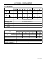
2-1. Specifications
Amperes Input At Rated Load Output, 60 Hz, Single-Phase
Model
200 (208) V 230 V 460 V 575 V KVA KW
AC 78 68 34 27 15.6 11.8
250P
DC 57 50 25 20 11.5 8.2
While Idling (25) (21.8) (11) (8.9) (5.0) (0.45)
AC 103 90 45 36 20.7 11.8
250
DC 80 70 35 28 16.1 8.2
While Idling (4.1) (3.6) (1.7) (2.2) (0.8) (0.6)
Rated Welding Output:
AC Mode
250 A @ 30 Volts AC, 30% Duty Cycle
Rated Welding Output:
DC Mode
200 A @ 28 Volts DC, 50% Duty Cycle
Max Open-Circuit
Voltage AC
70
Max Open-Circuit
Voltage DC
79
Amperes Input At Rated Load Output, 50 Hz, Single-Phase
Model
220 V 380 V 440 V KVA KW
AC 84 48.6 42 18.5 11
250
DC 68 39.3 34 14.9 11
While Idling (10.0) (5.3) (4.8) (2.1) (0.6)
Rated Welding Output: AC Mode
250 A @ 30 Volts AC, 30% Duty Cycle
Rated Welding Output: DC Mode
200 A @ 28 Volts DC, 50% Duty Cycle
Max Open-Circuit Voltage AC
70
Max Open-Circuit Voltage DC
79

OM-321 Page 10
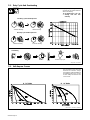
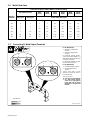
2-2. Duty Cycle And Overheating
5 Minutes Welding 5 Minutes Resting
3 Minutes Welding 7 Minutes Resting
rduty1 5/95 – 002 120-B
Duty Cycle is percentage of 10 min-
utes that unit can weld at rated load
without overheating.
Y Exceeding duty cycle can
damage unit and void
warranty.
30% Duty Cycle At 250 Amperes AC
50% Duty Cycle At 200 Amperes DC
Overheating
0
15
A
OR
Reduce Duty Cycle
Minutes
2-3. Volt-Ampere Curves
ssb1.1 10/91 – 002 696-A / 002 689-A
The volt-ampere curves show the
minimum and maximum voltage
and amperage output capabilities of
the welding power source. Curves
of other settings fall between the
curves shown.
A. DC Mode B. AC Mode

OM-321 Page 11
2-4. Dimensions And Weights
Dimensions
Height 24-1/4 in (616 mm)
Width 19 in (483 mm)
Length 28 in (711 mm)
A 3/4 in (19 mm)
B 26-1/2 in (673 mm)
Front
C 27-1/4 in (692 mm)
D 28 in (711 mm)
E 7/8 (22 mm)
F 17-7/8 (454 mm)
8 Holes
H
G 19 (483 mm)
8 Holes
H
H 1/2 in (13 mm) Dia
Weight
802 935
250 360 lbs (163 kg)
250P 365 lbs (166 kg)
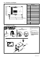
2-5. Selecting A Location
1 Rating Label
Use rating label to determine input
power needs. Label located on front
panel.
2 Line Disconnect Device
Locate unit near correct input pow-
er supply.
Y Special installation may be
required where gasoline or
volatile liquids are present –
see NEC Article 511 or CEC
Section 20.
2
18 in
(460 mm)
18 in
(460 mm)
Movement
Location And Airflow
1
Y Do not move or operate unit
where it could tip.
Tipping
loc_1 3/96 / 802 938

OM-321 Page 12
2-6. Weld Cable Sizes
Total Cable (Copper) Length In Weld Circuit Not Exceeding
100 ft (30 m) Or Less
150 ft
(45 m)
200 ft
(60 m)
250 ft
(70 m)
300 ft
(90 m)
350 ft
(105 m)
400 ft
(120 m)
Welding
Amperes
10 To 60%
Duty Cycle
60 Thru 100%
Duty Cycle
10 Thru 100% Duty Cycle
100 4 4 4 3 2 1 1/0 1/0
150 3 3 2 1 1/0 2/0 3/0 3/0
200 3 2 1 1/0 2/0 3/0 4/0 4/0
250 2 1 1/0 2/0 3/0 4/0 2-2/0 2-2/0
300 1 1/0 2/0 3/0 4/0 2-2/0 2-3/0 2-3/0
350 1/0 2/0 3/0 4/0 2-2/0 2-3/0 2-3/0 2-4/0
400 1/0 2/0 3/0 4/0 2-2/0 2-3/0 2-4/0 2-4/0
*Weld cable size (AWG) is based on either a 4 volts or less drop or a current density of at least 300 circular mils per ampere. S-0007-D
2-7. Connecting To Weld Output Terminals
800 052-A / 802 939
For DC Weld Output
1 Negative (–) Weld Output
Terminal
2 Positive (+) Weld Output
Terminal
For Electrode Positive (DCEP),
connect work cable to Negative (–)
terminal and electrode holder cable
to Positive (+) terminal.
For Electrode Negative (DCEN),
reverse cable connections.
For AC Weld Output
3 Work Weld Output Terminal
4 Electrode Weld Output
Terminal
Connect work cable to Work
terminal and electrode cable to
Electrode terminal.
Close access door.
Y Use only one set of terminals
at a time. Range Selector
switch S2 is only high/low
range; both sets of output
terminals are energized all
the time.
Tools Needed:
12
34
3/4 in

OM-321 Page 13
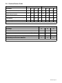
2-8. Electrical Service Guide
60 Hertz Models With Power Factor Correction Without Power Factor Correction
Input Voltage
200
(208)
230 460 575
200
(208)
230 460 575
Input Amperes At Rated Output
78 68 34 27 103 90 45 36
Max Recommended Standard Fuse Or Circuit
Breaker Rating In Amperes
125 100 50 40 150 125 70 50
Min Input Conductor Size In AWG/Kcmil
8 8 12 14 6 8 10 12
Max Recommended Input Conductor Length
In Feet (Meters)
61 (19) 80 (25)
131
(40)
133
(40)
87 (27) 77 (23)
208
(64)
200
(61)
Min Grounding Conductor Size In AWG/Kcmil
8 8 12 14 6 8 10 12
Reference: 1993 National Electrical Code (NEC) S-0092-J
50 Hertz Models Without Power Factor Correction
Input Voltage
220 380 440
Input Amperes At Rated Output
84 49 42
Max Recommended Standard Fuse Or Circuit Breaker Rating In Amperes
125 70 60
Min Input Conductor Size In AWG/Kcmil
8 10 10
Max Recommended Input Conductor Length In Feet (Meters)
76 (23) 153 (47) 205 (63)
Min Grounding Conductor Size In AWG/Kcmil
8 10 10
Reference: 1993 National Electrical Code (NEC) S-0092-J

OM-321 Page 14
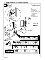
2-9. Placing Jumper Links And Connecting Input Power
input_3 3/96 - 802 940
Y Have only qualified persons
make this installation. See
rating label in Section 2-5,
and be sure to supply correct
input power.
Check input voltage available at
site.
Remove side panel.
1 Jumper Link Label
Check label – only one is on unit.
Move jumper links to match input
voltage, and label on unit.
2 Input And Grounding
Conductors
See Section 2-8.
3 Line Disconnect Device
See Section 2-8.
Connect input power.
Reinstall side panel.
L1
L2
3/8, 7/16, 1/2 in
208 VOLTS
S-035 209-A
LL
230 VOLTS
LL
460 VOLTS
LL
575 VOLTS
LL
230 VOLTS
LL
460 VOLTS
LL
S-010 587-B
575 VOLTS
LL
1
230 VOLTS 460 VOLTS200 VOLTS
S-083 566-C
LL LL LL
2
S-021 145-B
220 VOLTS
LL
380 VOLTS
LL
440 VOLTS
LL
Do not overtighten.
3
Y Always connect
grounding conductor first.
= GND/PE
L1
L2
GND/PE

OM-321 Page 15
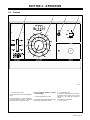
SECTION 3 – OPERATION
3-1. Controls
202 313
1 Range Selector Switch
Use switch to select ac or dc weld amperage
range.
If desired amperage is in the overlapping
area of two ranges, set switch in the lower
range for better fine amperage control.
Y Do not change position of switch
while welding.
2 Amperage Adjustment Control
Use control to adjust amperage within range
selected by Range Selector switch.
3 Circuit Breaker CB1
If CB1 opens, weld output drops to the mini-
mum of the range selected, and cannot be
adjusted by the Amperage Adjustment
control.
Press button to reset breaker.
4 Power Switch
1 2 3 4

OM-321 Page 16
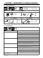
SECTION 4 – MAINTENANCE & TROUBLESHOOTING
4-1. Routine Maintenance
. Maintain more often
during severe conditions.
Y Disconnect power
before maintaining.
3 Months
Replace
Unreadable
Labels
Repair Or
Replace
Cracked
Weld
Cable
3 Months 6 Months
Clean
And
Tighten
Weld
Terminals
Blow Out
Or
Vacuum
Inside
During Heavy
Service,
Clean Monthly
OR
4-2. Troubleshooting
Trouble Remedy
No weld output. Place Power switch in the On position (see Section 3-1).
Place line disconnect switch in the On position (see Section 2-9).
Check line fuse(s); replace if open or reset circuit breaker(s) (see Section 2-9).
Check for proper input connections (see Section 2-9).
Check for proper jumper link position (see Section 2-9).
Erratic or improper weld output. Use proper size and type weld cable (see Section 2-6).
Clean and tighten all weld connections (see Section 4-1).
Be sure electrode is dry and proper type for SMAW.
Check connections at input terminal board TE1 (see Section 2-9).
Fan motor FM does not run. Check line fuse(s); replace if open or reset circuit breaker(s) (see Section 2-9).
Check and clear blocked fan blade.
Have Factory Authorized Service Agent check fan motor.
Low weld output. Check for proper input connections (see Section 2-9).
Check for proper jumper link positions (see Section 2-9).
Use proper size and type weld cable (see Section 2-6).
Clean and tighten all weld connections (see Section 4-1).
Low weld output; Amperage Adjustment control does
not control weld output.
Reset control circuit overload breaker CB1 (see Section 3-1).
Page is loading ...

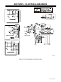
OM-321 Page 18
SECTION 6 – PARTS LIST
802 879
. Hardware is common and
not available unless listed.
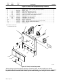
Figure 6-1. Main Assembly

OM-321 Page 19
Description
Quantity
Part
No.
Dia.
Mkgs.
Item
No.
Figure 6-1. Main Assembly
1 202 390 COVER, top 1. . . . . . . . . . . . . . . . . . . . . . . . . . . . . . . . . . . . . . . . . . . . . . . . . . . . . . . . . . . . . . . . . . . . . . . .
2 168 384 LABEL, warning electric shock can kill 1. . . . . . . . . . . . . . . . . . . . . . . . . . . . . . . . . . . . . . . . . . . . . . . . . .
3 +202 393 PANEL, side 2. . . . . . . . . . . . . . . . . . . . . . . . . . . . . . . . . . . . . . . . . . . . . . . . . . . . . . . . . . . . . . . . . . . . . .
4 202 394 FRAME, lifting 1. . . . . . . . . . . . . . . . . . . . . . . . . . . . . . . . . . . . . . . . . . . . . . . . . . . . . . . . . . . . . . . . . . . . . . .
5 026 627 GASKET, lifting eye cover 1. . . . . . . . . . . . . . . . . . . . . . . . . . . . . . . . . . . . . . . . . . . . . . . . . . . . . . . . . . . .
6 MA1 202 567 AMPLIFIER, magnetic (60 Hz) 1. . . . . . . . . . . . . . . . . . . . . . . . . . . . . . . . . . . . . . . . . . . . . . . . . .
6 MA1 202 991 AMPLIFIER, magnetic (50 Hz) 1. . . . . . . . . . . . . . . . . . . . . . . . . . . . . . . . . . . . . . . . . . . . . . . . . .
7 Z1 202 570 STABILIZER 1. . . . . . . . . . . . . . . . . . . . . . . . . . . . . . . . . . . . . . . . . . . . . . . . . . . . . . . . . . . . . . . . . . . .
8 092 614 ANGLE, mtg front transformer & stabilizer 2. . . . . . . . . . . . . . . . . . . . . . . . . . . . . . . . . . . . . . . . . . . . . .
9 T1 202 569 TRANSFORMER, pwr main 200(208)/230/460 (60 hz) 1. . . . . . . . . . . . . . . . . . . . . . . . . . . . . . . .
9 T1 203 698 TRANSFORMER, pwr main 230/460/575 (60 Hz) 1. . . . . . . . . . . . . . . . . . . . . . . . . . . . . . . . . . . .
9 T1 202 993 TRANSFORMER, pwr main 220/380/440 (50 Hz) 1. . . . . . . . . . . . . . . . . . . . . . . . . . . . . . . . . . . .
9 T1 203 697 TRANSFORMER, pwr main 200(208)/230/460/575 (60 Hz) 1. . . . . . . . . . . . . . . . . . . . . . . . . . . .
10 025 141 BRACKET, mtg capacitor (907 015 w/PFC only) 1. . . . . . . . . . . . . . . . . . . . . . . . . . . . . . . . . . . . . . .
11 C1 114 543 CAPACITOR (907 015 w/PFC only) 2. . . . . . . . . . . . . . . . . . . . . . . . . . . . . . . . . . . . . . . . . . . . . .
12 SR2 035 704 RECTIFIER, integ 40A 800V 1. . . . . . . . . . . . . . . . . . . . . . . . . . . . . . . . . . . . . . . . . . . . . . . . . . .
13 Fig 6-4 PANEL, rear w/components 1. . . . . . . . . . . . . . . . . . . . . . . . . . . . . . . . . . . . . . . . . . . . . . . . . . . . . . . . .
14 TE1 034 587 TERMINAL ASSEMBLY, pri 1ph triple voltage 1. . . . . . . . . . . . . . . . . . . . . . . . . . . . . . . . . . . .
14 TE1 146 529 TERMINAL ASSEMBLY, pri 1ph four voltage 1. . . . . . . . . . . . . . . . . . . . . . . . . . . . . . . . . . . . .
15 202 467 BASE 1. . . . . . . . . . . . . . . . . . . . . . . . . . . . . . . . . . . . . . . . . . . . . . . . . . . . . . . . . . . . . . . . . . . . . . . . . . . .
16 Fig 6-2 PANEL, front w/components 1. . . . . . . . . . . . . . . . . . . . . . . . . . . . . . . . . . . . . . . . . . . . . . . . . . . . . . . . .
+When ordering a component originally displaying a precautionary label, the label should also be ordered.
To maintain the factory original performance of your equipment, use only Manufacturer’s Suggested
Replacement Parts. Model and serial number required when ordering parts from your local distributor.

OM-321 Page 20
Description
Quantity
Part
No.
Dia.
Mkgs.
Item
No.
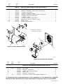
Figure 6-2. Panel, Front w/Components (Fig 6-1 Item 16)
1 NAMEPLATE, (order by model and serial number) 1. . . . . . . . . . . . . . . . . . . . . . . . . . . . . . . . . . . . . . . . . . . . . .
2 +202 391 PANEL, front 1. . . . . . . . . . . . . . . . . . . . . . . . . . . . . . . . . . . . . . . . . . . . . . . . . . . . . . . . . . . . . . . . . . . . .
3 S2 088 087 SWITCH, range 2posn (Fig 6-3) 1. . . . . . . . . . . . . . . . . . . . . . . . . . . . . . . . . . . . . . . . . . . . . . . . .
4 R2 083 671 RHEOSTAT, WW 150W 15 ohm 1. . . . . . . . . . . . . . . . . . . . . . . . . . . . . . . . . . . . . . . . . . . . . . . . .
5 CB1 083 432 CIRCUIT BREAKER, man reset 1P 10A 250V 1. . . . . . . . . . . . . . . . . . . . . . . . . . . . . . . . . . .
6 S1 128 757 SWITCH, tgl DPST 60A 600VAC scr term 1. . . . . . . . . . . . . . . . . . . . . . . . . . . . . . . . . . . . . . . . .
7 Elect,Work 099 255 TERMINAL, pwr output neutral 2. . . . . . . . . . . . . . . . . . . . . . . . . . . . . . . . . . . . . . . . . .
8 Pos 039 047 TERMINAL, pwr output red 1. . . . . . . . . . . . . . . . . . . . . . . . . . . . . . . . . . . . . . . . . . . . . . . . . . . .
9 Neg 039 046 TERMINAL, pwr output black 1. . . . . . . . . . . . . . . . . . . . . . . . . . . . . . . . . . . . . . . . . . . . . . . . . .
10 +202 395 DOOR, access front 1. . . . . . . . . . . . . . . . . . . . . . . . . . . . . . . . . . . . . . . . . . . . . . . . . . . . . . . . . . . . . . .
11 161 415 LABEL, warning electric shock can kill (output studs) 1. . . . . . . . . . . . . . . . . . . . . . . . . . . . . . . . . . .
12 134 327 LABEL, warning general precautionary 1. . . . . . . . . . . . . . . . . . . . . . . . . . . . . . . . . . . . . . . . . . . . . . . .
13 097 926 KNOB, pointer 1. . . . . . . . . . . . . . . . . . . . . . . . . . . . . . . . . . . . . . . . . . . . . . . . . . . . . . . . . . . . . . . . . . . . .
802 880
. Hardware is common and
not available unless listed.
2
3 FIG 6–3
4
5
6
9
8
7
10
12
13
11
1
Figure 6-2. Panel, Front w/Components
+When ordering a component originally displaying a precautionary label, the label should also be ordered.
To maintain the factory original performance of your equipment, use only Manufacturer’s Suggested
Replacement Parts. Model and serial number required when ordering parts from your local distributor.

OM-321 Page 21
Description Quantity
Part
No.
Item
No.
088 087
Figure 6-3. Switch, Range 2 Position (Fig 6-2 Item 3)
1 072 026 BRACKET, mtg switch 1. . . . . . . . . . . . . . . . . . . . . . . . . . . . . . . . . . . . . . . . . . . . . . . . . . . . . . . . . . . . .
2 164 169 CONTACT ASSEMBLY, switch 2posn (consisting of) 1. . . . . . . . . . . . . . . . . . . . . . . . . . . . . . . . . . .
3 072 028 GUIDE, contact switch 1. . . . . . . . . . . . . . . . . . . . . . . . . . . . . . . . . . . . . . . . . . . . . . . . . . . . . . . . . . . . .
4 011 644 CONTACT, stationary switch 2. . . . . . . . . . . . . . . . . . . . . . . . . . . . . . . . . . . . . . . . . . . . . . . . . . . . . . . .
5 011 645 CONTACT ASSEMBLY, movable switch (consisting of) 1. . . . . . . . . . . . . . . . . . . . . . . . . . . . . . . . .
6 011 075 SPRING, pressure contact switch 1. . . . . . . . . . . . . . . . . . . . . . . . . . . . . . . . . . . . . . . . . . . . . . . . . . . .
7 011 953 CONTACT, switch 2. . . . . . . . . . . . . . . . . . . . . . . . . . . . . . . . . . . . . . . . . . . . . . . . . . . . . . . . . . . . . . . . .
8 011 074 SPRING, pressure contact switch 1. . . . . . . . . . . . . . . . . . . . . . . . . . . . . . . . . . . . . . . . . . . . . . . . . . . .
9 072 082 BUSHING, stl .265 ID x .484 OD x .593 lg 1. . . . . . . . . . . . . . . . . . . . . . . . . . . . . . . . . . . . . . . . . . . .
10 072 027 LEVER, switch 1. . . . . . . . . . . . . . . . . . . . . . . . . . . . . . . . . . . . . . . . . . . . . . . . . . . . . . . . . . . . . . . . . . .
11 005 558 SPRING, selector switch 1. . . . . . . . . . . . . . . . . . . . . . . . . . . . . . . . . . . . . . . . . . . . . . . . . . . . . . . . . . .
Figure 6-3. Switch, Range 2 Position
1
3
5
6
7
8
9
10
11
089 628-A
4
2
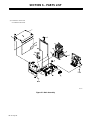
Figure 6-4. Panel, Rear w/Components
802 881
3
5
6
4
. Hardware is common and
not available unless listed.
1
2
Description
Quantity
Part
No.
Dia.
Mkgs.
Item
No.
Figure 6-4. Panel, Rear w/Components (Fig 6-1 Item 13)
1 SR1 202 580 RECTIFIER 1. . . . . . . . . . . . . . . . . . . . . . . . . . . . . . . . . . . . . . . . . . . . . . . . . . . . . . . . . . . . . . . . .
2 172 632 BRACKET, mtg rectifier 2. . . . . . . . . . . . . . . . . . . . . . . . . . . . . . . . . . . . . . . . . . . . . . . . . . . . . . . . . . . . .
3 180 165 BLADE, fan 14.000 3wg 23deg 1. . . . . . . . . . . . . . . . . . . . . . . . . . . . . . . . . . . . . . . . . . . . . . . . . . . . . .
4 202 392 PANEL, rear 1. . . . . . . . . . . . . . . . . . . . . . . . . . . . . . . . . . . . . . . . . . . . . . . . . . . . . . . . . . . . . . . . . . . . . . .
5 124 274 BRACKET, mtg fan motor 1. . . . . . . . . . . . . . . . . . . . . . . . . . . . . . . . . . . . . . . . . . . . . . . . . . . . . . . . . . .
6 FM 116 190 MOTOR, fan 1/12HP 230V 1550RPM 50/60Hz 1.5A 1. . . . . . . . . . . . . . . . . . . . . . . . . . . . . . . .
To maintain the factory original performance of your equipment, use only Manufacturer’s Suggested
Replacement Parts. Model and serial number required when ordering parts from your local distributor.
Page is loading ...
Page is loading ...
Page is loading ...
-
 1
1
-
 2
2
-
 3
3
-
 4
4
-
 5
5
-
 6
6
-
 7
7
-
 8
8
-
 9
9
-
 10
10
-
 11
11
-
 12
12
-
 13
13
-
 14
14
-
 15
15
-
 16
16
-
 17
17
-
 18
18
-
 19
19
-
 20
20
-
 21
21
-
 22
22
-
 23
23
-
 24
24
-
 25
25
-
 26
26
-
 27
27
-
 28
28


Miller DIALARC 25 Owner's manual
- Category
- Welding System
- Type
- Owner's manual
- This manual is also suitable for
Ask a question and I''ll find the answer in the document
Finding information in a document is now easier with AI
in other languages
Related papers
-
Miller AUTO ARC 140 Owner's manual
-
-
-
-
-
-
-
-
-