14 English
Installation instructions
Grounding
• All cooktops must be grounded for personal safety.
• The plug must be rmly plugged into a three-prong outlet that is properly
installed and grounded in accordance with all local codes and ordinances. In
the event of a malfunction or breakdown, grounding will decrease the risk of
electrical shock by providing a path for the electric current.
• Do not use a damaged power plug or loose wall outlet.
• Do not use an extension cord or adapter with this appliance
• Do not, under any circumstances, cut, modify, remove, or otherwise defeat the
grounding (third) prong from the power cord. If the plug and the outlet do not
match or you have any doubt, have a qualied electrician install the proper
outlet. The customer should have the wall receptacle and circuit checked by a
qualied electrician to make sure the receptacle is properly grounded.
• NEVER connect ground wire to plastic plumbing lines, gas lines, or water pipes.
CAUTION
Failure to follow these instructions can result in death, re, or electrical shock.
Additional installation requirements for mobile homes
The installation of appliances designed for mobile home installation must conform
with the Manufactured Home Construction and Safety Standard, Title 24 CFR, Part
3280 (formerly the Federal Standard for Mobile Home Construction and Safety,
Title 24, HUD, Part 280) or, when such standard is not applicable, the Standard
for Manufactured Home Installations, latest edition (Manufactured Home Sites,
Communities and Set-Ups), ANSI A225.1, latest edition, or with local codes. In
Canada, mobile home installation must be in accordance with the current CAN/CSA
Z240/MH Mobile Home Installation Code.
Installation instructions
Installing your gas cooktop
IMPORTANT:
Please read the following instructions, as well as the Important Safety Instructions
section at the front of this manual, completely and carefully BEFORE installing
and/or operating the gas cooktop. Improper installation, adjustment, service, or
maintenance can cause personal injury or property damage.
NOTE
To ensure proper installation, we strongly recommend that you hire a professional
installer.
Step 1. Unpack the cooktop
Remove all packaging materials. Failure to remove packaging materials could
result in damage to the appliance.
Inventory all loose parts against the Parts supplied components listed on page 8.
Check for shipping damage and/or missing parts. Any damage and/or missing
parts should be reported to your local retailer.
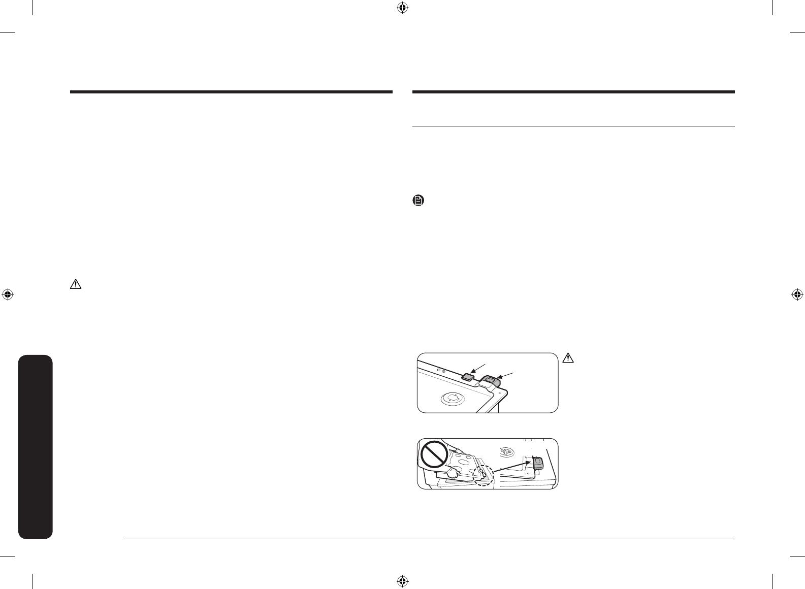
Step 2. Installing the cooktop.
Rubber
Smart Connect
module
CAUTION
• When inserting the cooktop into the
cutout opening, do not remove the
rubber piece protecting Smart Connect
module. Protecting rubber piece should
be removed after carefully inserting the
cooktop.
Smart Connect
module
• When mounting the cooktop, make sure to
insert the cooktop with the front side rst.
Inserting from the rear may damage the
Wi-Fi module.
Install_NA30N6555TG_DG68-01091A-01_EN+MES+CFR.indb 14 5/28/2018 12:50:36 PM


