Page is loading ...

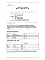
The AZEMT500B Thermostat is compatible with single and multistage forced air systems,
including:
• Gas furnace systems
• Oil furnace systems
• Electric furnace systems
• Heat pump systems
• Air conditioning cooling systems
The AZEMT500B Thermostat may be compatible with some other system types, including:
• Boiler systems
• Geothermal systems
• Multi-zoned systems
The AZEMT500B Thermostat is not compatible with the following system types:
• Radiant floor systems
• Wall heating systems
• Proprietary HVAC Communication Protocols
• 240 V Electric baseboard heating systems
Schlage LiNK™
Customer Service:
(877) 288-7707
Contents
Physical Installation and Wiring .......................................................................................................................................2
Field Wiring Diagrams .....................................................................................................................................................4
Enhanced Dehumidification Mode ...................................................................................................................................7
Optional Remote Temperature Sensors Installation ........................................................................................................ 8
System Settings at Thermostat ......................................................................................................................................10
Perform System Checkout .............................................................................................................................................12
Enroll Thermostat into Schlage LiNK™ System .............................................................................................................13
Product Specifications ...................................................................................................................................................14
Operation .......................................................................................................................................................................15
Menu Maps ....................................................................................................................................................................16
User Settings .................................................................................................................................................................18
Installer Settings ............................................................................................................................................................22
Dehumidification Options Settings .................................................................................................................................24
Dual Fuel Settings ..........................................................................................................................................................24
Schedules ......................................................................................................................................................................25
Limited Warranty ............................................................................................................................................................27
ÎNOTE: A 24 Volt common and hot wire MUST be connected to the
AZEMT500B for operation.
ÎThe AZEMT500B Thermostat is compatible with dual fuel systems
(gas or oil furnace & heat pump combined) without adding a dual fuel
accessory relay kit.
Thermostat
Installation and User Instructions
Models AZEMT500BB32MAA
11-HD10D1-2

2
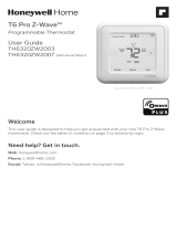
2 Remove the existing thermostat cover from the wall plate.
Leave wires attached.
MERCURY NOTICE
When this control is replacing an old control that contains mercury in a sealed tube, do
not dispose of your old control in the trash. Dispose of properly. Contact your local waste
management authority for instructions regarding recycling and proper disposal of the old
control.
A listing of heating, ventilating and air conditioning wholesalers that participate in the
Thermostat Recycling Corporation’s recycling program are available at
www.thermostat-recyle.org.
Wall plate
Thermostat cover
The look of the existing
thermostat may vary
1WARNING
Voltage hazard. Can cause electrical shock or equipment damage. Disconnect power to heating and
cooling equipment before beginning installation.
Physical Installation and Wiring

3
24RC
G
Y1
Y2
RS2
RS2
24C
24RH
W1
W2/O
RS1
RS2
Shld
HC
Shld
H1
5 Mark two mounting holes using new wall plate.
c. Pull wires through hole in center of wall plate.
d. Locate the new wall plate over existing opening.
e. Mark two holes with pencil.
f. Use a level to verify that the two hole locations are level.
g. Correct hole locations as needed.
6 Prepare two mounting holes.
h. Drill 1/16” pilot holes in the two locations that were marked in step 9. If mounting to drywall with no
studs behind it, enlarge pilot holes to 1/8” for anchors (included with the thermostat).
i. If using anchors, screw them into the holes.
8 Attach all wires securely to the new thermostat.
(See the Field Wiring Diagrams on the following page.)
Note: A wire must be connected to “24COM” to power the thermostat.
a. Use the information from the Field Wiring Diagrams to match the wires to the correct terminals.
b. Use 1/8” blade screwdriver to secure wires in terminals.
CAUTION: EQUIPMENT DAMAGE HAZARD
Improper wiring can lead to equipment damage. Follow the Terminal Connection information from step 6
carefully to ensure the control is wired properly. After wires are secure, bare wires MUST NOT touch each
other. See the Field Connection Wiring Diagrams on the following pages for specific system applications.
7 Install new wall plate.
c. Pull wires through hole in center of wall plate.
d. Locate the new wall plate over existing opening.
e. Attach wall plate to wall using two screws provided. Do not overtighten.
Anchors
Wall plate
24RC
G
Y1
Y2
RS2
RS2
24C
24RH
W1
W2/O
RS1
RS2
Shld
HC
Shld
H1
24RC
G
Y1
Y2
RS2
RS2
24C
24RH
W1
W2/O
RS1
RS2
Shld
HC
Shld
H1
24RC
G
Y1
Y2
RS2
RS2
24C
24RH
W1
W2/O
RS1
RS2
Shld
HC
Shld
H1
4 Separate the face of the new thermostat from the wall plate.
Apply pressure at two tabs on top of wall plate to release it.
ÎNOTE: It is not recommended that this Z-waveTM thermostat be mounted onto metal structures.
Metal may adversely affect the radio frequency (RF) communication between the thermostat and the
Z-waveTM bridge.
3 Remove existing wall plate.
ÎNote: During this process, make sure that the wires do not pull back into wall opening.
a. Detach all wires from wall plate.
b. Remove all screws attaching the wall plate to the wall and remove wall plate.
ÎSee Mercury Notice on page .

4
Field Wiring Diagrams
The following table can be used to find the correct field connection wiring diagram for the HVAC System Type that is being installed.
Indoor Unit Outdoor Unit
1 Stage
Cooling
2 Stage
Cooling
2 Step
Cooling
1 Stage
Heat Pump
2 Stage
Heat Pump
2 Step Heat
Pump
1 or 2 Stage Gas Furnace (PSC/CTM) A NA NA C 1NA NA
2 Stage VSPD Gas Furnace A A B C 1C 1D 1
COM Furnace A A A C 1C 1C 1
Air Handler (PSC/CTM) A NA NA C NA NA
VSPD Air Handler A A B C C D
COM Air Handler A A A C C C
Oil Furnace (PSC) E NA NA E 1NA NA
Oil Furnace (VSPD) E E F E 1E 1F 1
Enhanced Dehumidification Mode See Notes 3, 4
1 For heat pumps matched with furnace, Dual Fuel must be enabled in the Mechanical Settings menu.
2 BAYSEN01ATEMPA is required for “restricted” mode of operation. See Remote Temperature Sensor Installation.
3 Enhanced Dehumidification Mode is not applicable with 2 Step outdoor products combined with legacy variable speed indoor
products that use BK for high stage airflow: System types B, D, or F.
4 Smart Continuous Fan and Cooling Droop are available for all models.
Gas Furnace or Air Handler
System Type A - 1 or 2 Stage Heating with 1 or 2 Stage Cooling
Fan G
Heat Stage 1 W1
Compressor Stage 1 Y1
24VAC Return R
24VAC Common B/C
Compressor Stage 2 Y2
BK
Heat Stage 2 W2
RED
GREEN
WHITE
YELLOW
BLUE
BROWN
Remote Temperature Sensor Connections and Operation:
Indoor sensor connected to RS1. Replaces internal sensor. RS2 not connected.
Indoor sensor connected to RS2. Averages temperature with internal sensor. RS1 not connected.
Indoor sensors connected to RS1 and RS2. Averages RS1 and RS2 sensor temperatures.
Internal sensor is not used.
Outdoor sensor connected to RS2. Reports outdoor temperature to comfort control.
Indoor sensor connected to RS1 and outdoor sensor connected to RS2. RS1 replaces the internal
sensor. RS2 reports the outdoor temperature to comfort control.
Note 1 - May be W or W1. For systems with more than one W terminal,
a field installed jumper may be required for W1 to W2 and W3.
(Note 1)
(Note 5)
(Note 2)
(Note 3, Note 4)
Note 2 - May be Y, Y1, or YLO
Note 3 - May be Y or Y2
Note 5 - R required for 2 stage cooling unit
Note 6 - For 2 Stage Cooling, outdoor unit contains two compressors
Note 7 - Remote sensor wiring is not polarized.
Note 8 - JP1 is an internal RC to RH jumper
Note 4 - Y2 only found on variable speed
furnace or air handler
(Note 6)
Outdoor Unit
Compressor Stage 1 Y1
24VAC Return R
24VAC Common B
Compressor Stage 2 Y2
ORANGE
JP1: Internal RC to
RH jumper
W1 HEAT
24RC
24RH
G Fan
W2/O
Y1 Comp
Y2 Comp
24C
RS1
RS1
Sensor Shield
Sensor Shield
H1
HC
RS2
RS2
Thermostat Connection
Remote
Sensor 1
Remote
Sensor 2

5
Gas Furnace or Air Handler
Fan G
Heat Stage 1 W1
Compressor Stage 1
YLO
24VAC Return R
24VAC Common B/C
Compressor Stage 2
Y
BK
Heat Stage 2 W2
RED
GREEN
WHITE
YELLOW
BLUE
BROWN
Remote Temperature Sensor Connections and Operation:
Indoor sensor connected to RS1. Replaces internal sensor. RS2 not connected.
Indoor sensor connected to RS2. Averages temperature with internal sensor. RS1 not connected.
Indoor sensors connected to RS1 and RS2. Averages RS1 and RS2 sensor temperatures.
Internal sensor is not used.
Outdoor sensor connected to RS2. Reports outdoor temperature to comfort control.
Indoor sensor connected to RS1 and outdoor sensor connected to RS2. RS1 replaces the internal
sensor. RS2 reports the outdoor temperature to comfort control.
Outdoor Unit
Compressor Stage 1 Y1
24VAC Return R
24VAC Common B
Compressor Stage 2 Y2
ORANGE
JP1: Internal RC to
RH jumper
O
W1 HEAT
24RC
24RH
G Fan
W2/O
Y1 Comp
Y2 Comp
24C
RS1
RS1
Sensor Shield
Sensor Shield
H1
HC
RS2
RS2
Thermostat Connection
Remote
Sensor 1
Remote
Sensor 2
System Type B - 2 Stage Variable Speed Gas Furnace or Variable Speed Air Handler with 2 Step Cooling
Note 1 - Field installed jumper from R to O.
(Note 1)
(Note 7)
(Note 2)
(Note 5)
Note 2 - Cut/remove R to BK jumper
Note 3 - For non-communicating variable speed air handler.
(For communicating air handler, use system type A diagram.)
(Note 3, Note 4)
Note 4 - For 2 Step Cooling, outdoor unit contains one 2 stage scroll compressor
Note 5 - JP1 is an internal RC to RH jumper
Note 6 - Remote sensor wiring is not polarized.
Note 7 - May be W or W1. For systems with more than one W terminal,
a field installed jumper is required for W1 to W2 and W3.
Air Handler or Gas Furnace
Fan G
Heat Stage 1 W1
Compressor Stage 1 Y1
24VAC Return R
24VAC Common B/C
Compressor Stage 2 Y2
BK
RED
GREEN
WHITE
YELLOW
BLUE
BROWN
Remote Temperature Sensor Connections and Operation:
Indoor sensor connected to RS1. Replaces internal sensor. RS2 not connected.
Indoor sensor connected to RS2. Averages temperature with internal sensor. RS1 not connected.
Indoor sensors connected to RS1 and RS2. Averages RS1 and RS2 sensor temperatures.
Internal sensor is not used.
Outdoor sensor connected to RS2. Reports outdoor temperature to comfort control.
Indoor sensor connected to RS1 and outdoor sensor connected to RS2. RS1 replaces the internal
sensor. RS2 reports the outdoor temperature to comfort control.
Outdoor Unit
Compressor Stage 1 Y1
24VAC Return R
24VAC Common B
Compressor Stage 2 Y2
ORANGE
JP1: Internal RC to
RH jumper
O
W1 HEAT
24RC
24RH
G Fan
W2/O
Y1 Comp
Y2 Comp
24C
RS1
RS1
Sensor Shield
Sensor Shield
H1
HC
RS2
RS2
Thermostat Connection
Remote
Sensor 1
Remote
Sensor 2
Note 8 - Remote sensor wiring is not polarized.
Note 9 - For heat pumps matched with furnace, dual fuel must be enabled in the
“Mechanical Settings” menu. BAYSEN01ATEMPA required for “restricted”
mode of operation. See “Remote Temperature Sensor Installation”.
System Type C - PSC, CTM, Variable Speed, or 24 Volt Communicating Air Handler or gas furnace with 1 or 2 Stage/Step Heat Pump
Note 1 - May be W or W1. For systems with more than one W terminal,
a field installed jumper may be required for W1 to W2 and W3.
(Note 1)
(Note 2)
(Note 3)
(Note 4, Note 5, Note 6, Note 7, Note 9)
Note 2 - May be Y, Y1, or YLO
Note 3 - May be Y or Y2
Note 4 - Applies to 2 step heat pumps matched with communicating air handler or furnace only.
All other variable speed air handlers use system type D diagram.
Note 5 - For 2 Stage, outdoor unit contains two compressors
Note 6 - For 2 Step, outdoor unit contains one 2 stage scroll compressor
Note 7 - PSC CTM air handler or gas furnace for single stage heat pump only
(Note 8)
(Note 8)
X2
O

6
Air Handler or Gas Furnace
Fan G
Heat Stage 1 W1
Compressor Stage 1
Y1
24VAC Return R
24VAC Common B/C
Compressor Stage 2
Y2
BK
RED
GREEN
WHITE
YELLOW
BLUE
BROWN
Remote Temperature Sensor Connections and Operation:
Indoor sensor connected to RS1. Replaces internal sensor. RS2 not connected.
Indoor sensor connected to RS2. Averages temperature with internal sensor. RS1 not connected.
Indoor sensors connected to RS1 and RS2. Averages RS1 and RS2 sensor temperatures.
Internal sensor is not used.
Outdoor sensor connected to RS2. Reports outdoor temperature to comfort control.
Indoor sensor connected to RS1 and outdoor sensor connected to RS2. RS1 replaces the internal
sensor. RS2 reports the outdoor temperature to comfort control.
Outdoor Unit
Compressor Stage 1 Y1
24VAC Return R
24VAC Common B
Compressor Stage 2 Y2
ORANGE
JP1: Internal RC to
RH jumper
O
W1 HEAT
24RC
24RH
G Fan
W2/O
Y1 Comp
Y2 Comp
24C
RS1
RS1
Sensor Shield
Sensor Shield
H1
HC
RS2
RS2
Thermostat Connection
Remote
Sensor 1
Remote
Sensor 2
(Note 1)
(Note 2)
(Note 4)
(Note 4)
X2
O
System Type D - Variable Speed Air Handler or Furnace with 2 Step Heat Pump
Note 1 - Field installed jumper from R to O
Note 2 - Remove R to BK jumper
Note 3
Note 3 - For 2 Step Heat Pump, outdoor unit contains one 2 stage scroll compressor
Note 4 - Remote sensor wiring is not polarized
Note 5 - For Heat Pumps matched with furnace, dual fuel must be enabled in the
“Mechanical Settings” menu. BAYSEN01ATEMPA required for “restricted”
mode of operation. See “Remote Temperature Sensor Installation”.
Fan G
Heat Stage 1 W1
Compressor Stage 1 Y1
24VAC Return R
24VAC Common B/C
Compressor Stage 2
Y2
BK
RED
GREEN
WHITE
YELLOW
BLUE
BROWN
Remote Temperature Sensor Connections and Operation:
Indoor sensor connected to RS1. Replaces internal sensor. RS2 not connected.
Indoor sensor connected to RS2. Averages temperature with internal sensor. RS1 not connected.
Indoor sensors connected to RS1 and RS2. Averages RS1 and RS2 sensor temperatures.
Internal sensor is not used.
Outdoor sensor connected to RS2. Reports outdoor temperature to comfort control.
Indoor sensor connected to RS1 and outdoor sensor connected to RS2. RS1 replaces the internal
sensor. RS2 reports the outdoor temperature to comfort control.
Outdoor Unit
Compressor Stage 1 Y1
24VAC Return R
24VAC Common B
Compressor Stage 2 Y2
ORANGE
JP1: Internal RC to
RH jumper
O
W1 HEAT
24RC
24RH
G Fan
W2/O
Y1 Comp
Y2 Comp
24C
RS1
RS1
Sensor Shield
Sensor Shield
H1
HC
RS2
RS2
Thermostat Connection
Remote
Sensor 1
Remote
Sensor 2
Oil Furnace-
PSC or Variable speed
System Type E - Oil Furnace with 1 or 2 Stage Cooling
or Heat Pump
Note 1 - May be Y, Y1, or YLO
(Note 1)
(Note 6)
Note 2 - May be Y or Y2
Note 3 - For variable speed oil furnaces, factory installed
jumpers R to O and R to BK
Note 4 - R to ODU required for 2 stage cooling models
Note 5 - Variable speed furnace required for 2 stage cooling
Note 6 - Field supplied Isolation Relay
(Note 4)
(Note 7)
(Note 2, Note 5)
(Note 3)
(Note 3)
R1
OIL BURNER PRIMARY
Note 7 - For 2 Stage, outdoor unit contains two compressors
Note 8 - For Heat Pumps matched with oil furnaces, dual fuel must be enabled in the
“Mechanical Settings” menu. BAYSEN01ATEMPA required for “restricted”
mode of operation. See “Remote Temperature Sensor Installation”.
Note 9 - Remote sensor wiring is not polarized
R1 (Isolation relay, See R1 below)
(Note 1)
(Note 9)
(Note 9)
X2
O

7
Fan G
Heat Stage 1 W1
Compressor Stage 1
YLO
24VAC Return R
24VAC Common C
Compressor Stage 2
Y
BK
RED
GREEN
WHITE
YELLOW
BLUE
BROWN
Remote Temperature Sensor Connections and Operation:
Indoor sensor connected to RS1. Replaces internal sensor. RS2 not connected.
Indoor sensor connected to RS2. Averages temperature with internal sensor. RS1 not connected.
Indoor sensors connected to RS1 and RS2. Averages RS1 and RS2 sensor temperatures.
Internal sensor is not used.
Outdoor sensor connected to RS2. Reports outdoor temperature to comfort control.
Indoor sensor connected to RS1 and outdoor sensor connected to RS2. RS1 replaces the internal
sensor. RS2 reports the outdoor temperature to comfort control.
Outdoor Unit
Compressor Stage 1 Y1
24VAC Return R
24VAC Common B
Compressor Stage 2 Y2
ORANGE
JP1: Internal RC to
RH jumper
O
W1 HEAT
24RC
24RH
G Fan
W2/O
Y1 Comp
Y2 Comp
24C
RS1
RS1
Sensor Shield
Sensor Shield
H1
HC
RS2
RS2
Thermostat Connection
Remote
Sensor 1
Remote
Sensor 2
(Note 1)
(Note 5)
(Note 4)
(Note 6)
(Note 2) (Note 3)
(Note 4)
(Note 3)
R1
OIL BURNER PRIMARY
R1 (Isolation relay, See R1 below)
(Note 1)
(Note 8)
(Note 8)
X2
O
Oil Furnace- Variable speed
System Type F - Variable Speed Oil Furnace with 2 Step Cooling
or Heat Pump
Note 1 - May be Y, Y1, or YLO
Note 2 - May be Y or Y2
Note 3 - Factory installed jumpers R to O and R to BK
Note 4 - Cut / remove R to BK jumper for 2 step compressors
Note 5 - Field supplied Isolation Relay
Note 6 - For 2 Step, outdoor unit contains one 2 stage scroll compressor
Note 7 - For Heat Pumps matched with oil furnaces, dual fuel must be enabled in the
“Mechanical Settings” menu. BAYSEN01ATEMPA required for “restricted”
mode of operation. See “Remote Temperature Sensor Installation”.
Note 8 - Remote sensor wiring is not polarized
Variable speed
Gas Furnace or Air Handler
Fan G
Heat Stage 1 W1
Compressor Stage 1 Y1
24VAC Return R
24VAC Common B/C
Compressor Stage 2 Y2
BK
Heat Stage 2 W2
RED
GREEN
WHITE
YELLOW
BLUE
BROWN
BLACK
Remote Temperature Sensor Connections and Operation:
Indoor sensor connected to RS1. Replaces internal sensor. RS2 not connected.
Indoor sensor connected to RS2. Averages temperature with internal sensor. RS1 not connected.
Indoor sensors connected to RS1 and RS2. Averages RS1 and RS2 sensor temperatures.
Internal sensor is not used.
Outdoor sensor connected to RS2. Reports outdoor temperature to comfort control.
Indoor sensor connected to RS1 and outdoor sensor connected to RS2. RS1 replaces the internal
sensor. RS2 reports the outdoor temperature to comfort control.
Note 1 - May be W or W1. For systems with more than one W terminal,
a field installed jumper may be required for W1 to W2 and W3.
(Note 1)
(Note 5)
(Note 2)
(Note 3, Note 4)
Note 2 - May be Y, Y1, or YLO
Note 3 - May be Y or Y2
Note 5 - R required for 2 stage unit
Note 6 - For 2 Stage, outdoor unit contains two compressors
Note 7 - for heat pumps matched with furnace, Dual Fuel must
be enabled in the Mechanical Settings menu. BAYSEN01ATEMPA
is required for “restricted” mode of operation. See Remote
Temperature Sensor Installation.
Note 8 - Remote sensor wiring is not polarized.
Note 9 - Field installed jumper from R to HC
Note 10 - JP1 is an internal RC to RH jumper
Note 11 - Enhanced dehumidification must be enabled: See “Installer Settings” menu
Note 12 - Installer must cut or remove the R to BK jumper on variable speed
indoor unit
Note 4 - Y2 only found on variable speed
furnace or air handler
Outdoor Unit
Compressor Stage 1 Y1
24VAC Return R
24VAC Common B
Compressor Stage 2 Y2
ORANGE
(Note 11, Note 12)
W1 HEAT
24RC
24RH
G Fan
W2/O
Y1 Comp
Y2 Comp
24C
RS1
RS1
Sensor Shield
Sensor Shield
H1
HC
RS2
RS2
Thermostat Connection
Remote
Sensor 1
Remote
Sensor 2
Note 9
JP1: Internal RC to
RH jumper
Enhanced Dehumidification Mode
When the AZEMT500B is connected to variable speed indoor products,
the enhanced dehumidification mode can reduce indoor airflow to improve
dehumidification during the cooling run cycle. When 24 VAC is present at the BK terminal,
(HC to H1 = N.C.) airflow will be 100 percent. When 24 VAC is removed from BK,
(HC to H1 = N.O.) airflow will be reduced by 20 percent. See Notes 11 and 12.
HC to H1 = N.C. when RH% is lower than RH% setpoint
HC to H1 = N.O. when RH% is higher than RH% setpoint
Not applicable with 2 step outdoor products combined
with legacy variable speed indoor products that require
BK for high stage airflow: System Types B, D, or F on page 4.
Enhanced Dehumidification Mode

8
Wire specification (RS1 & RS2): 2 conductors, 18 gauge wire. Make sure that the sensor wires have a cable separate from the thermostat
cable. Best results for distances of 100 feet or less. Accuracy may be affected for distances up to a maximum of 200 feet. Shielded cable is
recommended for distances over 100 feet and less than 200 feet.
CAUTION: Keep this wiring at least one foot away from large inductive loads such as electronic air cleaners, motors,
line starters, lightning ballasts, and large distribution panels. Failure to follow these wiring practices may introduce electrical
interference (noise) which can cause erratic system operation. Shielded cable is required if the above wiring guidelines cannot be
met. Be sure to ground only one end of the shield to the thermostat common terminal. Tape back the other end of the shield.
Remote Sensors Part Numbers
Remote Indoor Sensor: Use ZZSENSAL0400AA for indoor applications.
Remote Outdoor Sensor: Use BAYSEN01ATEMPA for outdoor applications.
ÎIMPORTANT: Make sure that the sensor wires have a cable separate from the thermostat cable.
ÎIMPORTANT: Follow directions below for averaging. These instructions replace the averaging information found in the Installer’s
Guide for the ZZSENSAL0400AA.
ÎNote: Remote Sensor 2 can be selected as an indoor sensor or an outdoor sensor.
Remote Temperature Sensor Connections and Operation:
A) Indoor sensor connected to RS1. Replaces internal sensor. RS2 not connected.
Remote Sensor 1 (RS1) replaces the internal
temperature sensor of the thermostat. This allows the
thermostat to be installed in a location different than
the area where the temperature will be measured. Use
ZZSENSAL0400AA. See Figure A.
B) Indoor sensor connected to RS2. Averages
temperature with internal sensor. RS1 not
connected.
RS2 is used as an indoor temperature sensor that
averages temperatures with the internal sensor. Use
ZZSENSAL0400AA. See Figure B.
If RS2 is set to indoor location (“IN” - Default selection in
the thermostat installation set up menu) and a sensor is
attached to the RS2 sensor terminals of the thermostat,
the RS2 temperature is averaged with the thermostats
internal temperature sensor.
C) Indoor sensors connected to RS1 and RS2.
Averages RS1 and RS2 sensor temperatures.
Internal sensor is not used.
Remote Sensor 1 (RS1) and Remote Sensor 2 (RS2)
are both used as indoor sensors. The RS1 temperature
and RS2 temperature is averaged. See Figure C.
D) Outdoor sensor connected to RS2. Reports
outdoor temperature to comfort control.
RS2 is used as an outdoor temperature sensor. Use
BAYSEN01ATEMPA. See Figure B.
If RS2 is set to outdoor location (“OUT” in the thermostat installation set up menu) and a sensor is attached to the RS2 sensor terminals
of the thermostat, the RS2 temperature is used to report outdoor temperature. It is also displayed on the thermostat main screen. See
Step 15 to configure for outdoor temperature sensing.
E) Indoor sensor connected to RS1 and Outdoor sensor connected to RS2. RS1 replaces the internal sensor. RS2 reads the
outdoor temperature.
Remote Sensor 1 (RS1) replaces the internal temperature sensor of the thermostat. This allows the thermostat to be installed in a
location different than the area where the temperature will be measured. Use ZZSENSAL0400AA.
RS2 is used as an outdoor temperature sensor. Use BAYSEN01ATEMPA. See Figure C.
If RS2 is set to outdoor location (“OUT” in the thermostat installation set up menu) and a sensor is attached to the RS2 sensor terminals
of the thermostat, the RS2 temperature is used to report outdoor temperature. It is also displayed on the thermostat main screen. See
Step 15 to configure for outdoor temperature sensing.
RS1 Sensor
Remote Temp Sensor
Figure A
Sensor wiring is
not polarized.
Black
Red
RS1
RS1
RS2
RS2
RS2 Sensor
RS2
Remote Temp Sensor
Sensor wiring is
not polarized.
Black
Red
Figure B
RS1
RS1
RS2
RS2
RS2 Sensor
Figure C
RS1 Sensor
Remote Temp Sensor
Black
Red
RS1
RS1
RS2
RS2
RS2
Remote Temp Sensor
Sensor wiring is
not polarized.
Black
Red
Optional Remote Temperature Sensors Installation

9
9 If necessary, cut the internal jumper wire (JP1).
24RC
24RH
W1
24RC
24RH
W1
OR
24RC
24RH
W1
Do NOT cut JP1 jumper Cut JP1 jumper
If only one wire is connected
to either 24RC or 24RH
as shown
If wires are connected to
both 24RC and 24RH
as shown
Cutting the JP1 jumper
The jumper is located on back of the thermostat face as shown in the illustration to
the right. Cut the jumper using small diagonal cutters being careful not to damage
the board.
11 Turn power to heating and cooling system back on.
The thermostat display should turn on and begin displaying information. If the thermostat display does not come on, go back through the
installation steps and look for problems.
10 Attach the thermostat face to the wall plate.
a. Carefully align the face plate to the wall plate while aligning pins into wire terminals.
b. Once thermostat face is properly aligned, apply pressure at top and bottom of thermostat face
until it is secure.
24RC
G
Y1
Y2
RS2
RS2
24C
24RH
W1
W2/O
RS1
RS2
Shld
HC
Shld
H1
CUT JUMPER TO
SPLIT RC/RH
HC
SHLD
RS1
24C
24RH
W1
W2/O
RS1
H1
SHLD
RS2
24RC
G
Y1
Y2
RS2
JP1
JP1
JP1
CUT JUMPER TO
SPLIT RC/RH
SPLIT RC/RH
CUT JUMPER TO

10
13 If your System Type is:
• Gas Furnace - Single Stage, Perform System Checkout step 16
• Gas Furnace - Multistage, perform step 14 then step 14A
• Electric Furnace, perform step 14 then step 14B
• Heat Pump, perform step 14 then step 14C
• Heat Pump Dual Fuel, perform step 14 then step 14D
12 Set Time and Date
a. Press the Menu button twice.
MENU button
MENU MODE FAN RUN
75 76 H
74 C
11:15 AM
b. Scroll up or down to User Settings (it is the first option),
then press the Select button.
c. Scroll up or down to Set Clock (it is the first option), then
press the Select button.
Done Select
User Settings
Set Clock
Filter Service
Maint Service
Screen Timeout
Select button
Scroll
up
Scroll
down
d. Press or to highlight the data you want to change.
e. Scroll up or down (+ or -) to make changes.
f. Press the Set button when you are finished.
g. Press the Done button twice to exit the menu.
Set button
Scroll
up
Scroll
down
Back
Set Clock
Set
Time 10 :15 AM
Date 3 / 23 / 09
Day Mon
System Settings at Thermostat
Set button
Scroll
up
Scroll
down
Done
Set Clock
Set
User Settings
Usage Graph
ESM Setpoints
Z-Wave Install

11
Menu
button
MENU MODE FAN RUN
75
76 H
74 C
11:15 AM
Two inner
buttons
14A
14
14B
14C
14D
Select button
Scroll
up
Scroll
down
+ button
Done
Mechanical Settings
Select
Type Heatpump
Fan Type Elec
C/O Type w/Cool
2nd Stage Heat N
Mechanical Settings
a. Press the MENU button twice.
b. Press and hold the two inner buttons for 3 seconds to view
Installer Settings
c. Scroll down to System Settings and press the Select button.
d. Scroll to Mechanical Settings (it is the first option), then press
the Select button.
e. Choose option A-D below:
For Gas Furnace - Multistage Mechanical Settings
a. Scroll down to 2nd Stage Heat.
b. Press the + button to change the setting to Y for Yes.
c. If your system also has 2nd stage cooling, scroll down to 2nd
Stage Cool and Press the + button to change the setting to Y for
Ye s .
d. Press the Done button 4 times and go to Perform System
Checkout.
For Electric Furnace Mechanical Settings
a. Scroll down to Fan Type.
b. Press the + button to change the setting Electric.
ÎIf Single Stage System, press Done 4 times and go
to Perform System Checkout.
ÎIf Multistage System, continue with steps c through f.
c. Scroll down to 2nd Stage Heat.
d. Press the + button to change the setting to Y for Yes.
e. If your system also has 2nd stage cooling, scroll down to 2nd
Stage Cool and Press the + button to change the setting to Y for
Ye s .
f. Press the Done button 4 times and go to Perform System
Checkout.
Heat Pump Mechanical Settings
a. Scroll to system Type.
b. Press the + button to change the setting to Y to Heat Pump.
c. Scroll down to Fan Type.
d. Press the + button to change the setting to Electric.
e. If Coleman, Rheem, or Rudd brand heat pump, scroll to C/O Type
and change to With Heat.
ÎIf Single Stage System, press Done 4 times and go
to Perform System Checkout.
ÎIf Multistage System, continue with steps f through j.
f. Scroll down to 2nd Stage Heat.
g. Press the + button to change the setting to Y for Yes.
h. Scroll down to 2nd Stage Cool.
i. Press the + button to change the setting to Y for Yes.
j. Press the Done button 4 times and go to Perform System
Checkout.
Enable Dual Fuel
a. Scroll to system Type.
b. Press the + button to change the setting type to Heatpump DF. The
default control mode is Non-restricted.
c. To change to Restricted, scroll to DF Type Non-restricted. Press the
+ button to set the mode to Restricted.
d. If Non-restricted control mode was selected, press the Done button
4 times and go to Perform System Checkout.
e. If restricted control mode was selected, set the desired compressor
lockout temperature. Press the Done button 3 times then select
User Settings. Scroll down to Balance Point. Use the + and
- buttons to set the compressor lockout temperature. Default
compressor lockout temperature is 40°F.
f. Press the Done button 2 times and go to Perform System Checkout.

12
16 Test All Modes of Operation
Fan, Cooling, and Heating.
Perform System Checkout
15 Optional Remote Temperature Sensors Installation
Remote sensor input RS2 can be configured for use as indoor or outdoor temperature sensing. An outdoor temperature sensor is
required for Dual Fuel Restricted mode. The factory default setting for RS2 is “IN” for use with remote indoor temperature sensing and/or
averaging. To configure RS2 to sense outdoor temperature, complete the following steps:
a. Press the MENU button twice to access the Menu Selection screen.
b. From the Menu Selection screen, press and hold the two inner buttons down for 4 seconds to reach the Installer Settings menu.
c. From the Installer Settings screen, scroll down to Remote Sensors using the Scroll down button and press the Select button.
d. From the Remote Sensors screen, select the option for RS2 remote senor location. (IN is the factory default setting)
e. To change RS2 for use as an outdoor temperature sensor, press the + button to change this setting to OUT.
f. Press the Done button three times to return to the home screen.
Remote Sensors
RS2 Location IN
DONE + -
Press DONE button
to exit back to installer
settings screen. Press the +/- buttons to change the setting.

13
17 Prepare the bridge for enrollment.
ÎNote: If the bridge is already installed, follow the instructions as they are
written in the following steps. If the bridge is not installed, follow the Quick
Start Guide publication number shipped with the thermostat starter kit.
a. Unplug Ethernet and power cables from bridge.
b. Install a quality 9 volt battery.
c. Verify that blue light is blinking. If blue light is solid, battery is dead.
d. Take bridge to the location where the thermostat is mounted.
Blue
light
Battery
Enroll Thermostat into existing Schlage LiNK™ System
18 Enroll the thermostat into the bridge. (Inclusion)
If you are using a controller that is not a Schlage LiNKTM bridge, consult the Quick
Start Guide that came with the controller to find out how to enroll a new device.
a. Hold the bridge within 6 feet (1.8 meters) of the thermostat throughout steps
“b” through “f”.
ÎAfter you begin the enrollment process, you have 30 seconds to complete
the remainder of the steps. Study the steps below before beginning.
b. Press and release the plus (+) button on the bridge.
c. Press the MENU button on the thermostat.
d. Scroll down to Z Wave Install, and press the Select button.
e. Press the Yes button to enroll the thermostat.
f. Observe the lights on the bridge. The orange light will blink while enrollment
is taking place. Enrollment is complete when the orange light becomes solid.
MENU button
MENU MODE FAN RUN
75 76 H
74 C
11:15 AM
Gateway
24RC
G
Y1
Y2
RS2
RS2
24C
24RH
W1
W2/O
RS1
RS2
Shld
H1
Shld
H2
“+” Button
19 Verify enrollment of the thermostat.
a. Scroll down to Thermostat Info, and press the Select button.
b. Look at the number listed after ZNID.
• If the number listed there is anything other than “000”, the
thermostat has been successfully enrolled.
• If the number listed there is “000”, the thermostat has NOT
been successfully enrolled. In this case, repeat step 22 and
verify again.
c. Press Done button 2 times when finished.
Item Description
AZEMT500BB32 Model Number
Ver: 01.00.13 Firmware version (number may vary)
ZVER: 02.00.9 Z-Wave version (number may vary)
ZNID: 013 Z-Wave node ID (number may vary)
ZHID: 01.07.37.a7 Z-Wave Home ID (number may vary)
System Type: Standard System type may be Standard or Heat Pump
Fan Type: Gas Fan type may be Gas or Elect (electric)
ZNID
Done
Thermostat Info
AZEMT500BB32 Ver: 01.00.13
ZVER:02.00.0 ZNID: 013
ZHID: 01.07.37.a7
System Type: Standard
Fan Type: Gas
Done Select
Menu Selection
User Settings
Usage Graph
ESM Setpoints
ZWave Install
Select button
Scroll
down

14
20 Establish Online Control of the Thermostat.
Schlage LiNK account must be active before continuing. See link.schlage.com for more information.
a. Remove the battery from the bridge.
b. Plug the Ethernet and power cord back into the bridge.
c. Log into your account at www.schlagelink.com
d. Click the Climate tab and follow the on screen instructions.
Exclusion (Only used to unenroll a thermostat from the bridge)
a. Install a new, high-quality 9-volt battery into the bridge.
b. Hold the bridge within 6 feet (1.8 meters) of the thermostat throughout the entire exclusion process.
ÎAfter you begin the exclusion process, you have 30 seconds to complete the remainder of the steps. Study the steps below
before beginning.
c. Press and release the minus (-) button on the bridge.
d. Press the MENU button on the thermostat.
e. Scroll down to Z-Wave Install and press the Select button.
f. Press the Yes button to exclude the thermostat.
g. Observe the lights on the bridge. The orange light will blink while exclusion is taking place. Exclusion is complete when the orange
light becomes solid.
ÎZ-Wave™ controllers from various manufacturers may support the Z-Wave™ Thermostat General V2 Device class used by
the Z-Wave™ Thermostat. If you are using a controller that is not a Schlage bridge, consult the instructions that came with
the controller to find out how to enroll a new device.
Product Specifications
Specification Description
Product Model: AZEMT500BB32MAA
Product: Thermostat for Heating and Cooling HVAC System control.
Z-Wave™ RF communications enabled
Size: 5.7” wide x 4.0” height x 1.2” depth
Display: Graphical LCD, 2.75” x 1.5”, 64x128-pixel
Backlight: Yes, Blue/white, Controllable, on, off, timeout
Contrast: Adjustable on screen
Buttons: 6
Power: 24VAC from HVAC System
HVAC System Type Compatible: Standard (gas/electric), Heat Pump. or Dual Fuel
Multistage System Compatible: Standard HVAC Systems: 2 stage heating, 2-stage cooling, dual fuel
Heat Pump Systems: 3 stage heating (2-compressor, 1 aux heat), 2-stage cooling
Heat Pump change over valve: Selectable change over with cool or with heat
Communications: Z-Wave™ RF
Memory: Non-volatile
Clock: 24 hour back-up power provided by super capacitor

15
The model AZEMT500BB32MAA thermostat provides typical thermostat control of a central heating and cooling HVAC system. These
thermostats also features a Z-Wave™ module for remote control.
MENU
72 77 H
11:15 AM
Sys O
Run
Filter
Setpoint
Up/Down Buttons
Setpoint Display
Dynamic Labels
AUTO
MODE AUTO
FAN RUN
74 C
Clock Display
Tempurature
Display
System
Mode Button
Fan Mode
Button
Schedule
Mode Button
Menu Button
Normally, the thermostat displays the thermostat control screen as shown above.
Item Description Notes
Clock Display The current time is displayed in the upper left corner
of the main screen. The time will blink when the clock
has not been set.
See Set Clock for more information.
Dynamic Labels and
Function Control Buttons
The buttons are defined by the dynamic labels above
each button. As you navigate through menus, the
labels for the buttons will change.
Setpoint Display and
Setpoint Up/Down Buttons
The current heat and cool setpoints are displayed.
These setpoints may be set using the Z-Wave control
system, the thermostat’s internal schedule, or by
pressing the Setpoint Up/Down buttons. In HEAT
mode, the Setpoint Up/Down buttons change the heat
setpoint. In COOL mode, they change the cooling
setpoint. In AUTO mode, the buttons change the last
call’s heating or cooling setpoint.
The setpoints will push each other if they are adjusted
to within the minimum heat/cool separation setting.
This is normally 3 degrees.
The internal schedule is disabled by default. See
Schedules for more information.
Temperature Display The thermostat displays the current temperature as
sensed by the internal temperature sensor.
The internal temperature sensor can be adjusted as
necessary. See Internal Sensor Calibration for more
information.
Menu Button Button used to access other thermostat menus Other thermostat menus can be accessed by pressing
the MENU button.
System Mode Button Button used to change the system mode Off: System off
Heating: Heating only on
Cooling: Cooling only on
Auto: Heating/Cooling on as necessary
Fan Mode Button Button used to change the fan mode: Auto: Fan on when cooling/heating is necessary
On: Fan constantly on
Fan Cycler (note 1)
Smart Continuous Fan (notes 1, 2)
Schedule Mode Button Button used to change the schedule mode: Hold: System maintains the current temperature
setpoints. Schedules are disregarded.
Run: Run the system schedule (or Z-Wave controlled
schedule)
Energy Saving Mode: Temperature setpoints in ESM
Setpoints are maintained. See ESM Setpoints on for
more information.
Note 1 See the Installer Settings menu to enable
Note 2 See the User Settings menu to set RH setpoint
Operation

16
Minimized Display Mode
Optionally, you can set the thermostat to show only the temperature in
minimized display mode. This mode can be enabled or disabled in the
Users Settings screen.
ÎSee Screen Timeout for more information.
72
User settings are accessed by pressing the MENU button on the
main screen.
Schedule (if enabled) Note 1
User Settings
Set Clock
Filter Service
Maint Service
Screen Timeout
RH% Setpoint
Balance Point - Note 2
F/C Settings
F/C Mode
Sensor Calibration
Internal
Remote 1
Remote 2
Outside
Backlite/Display
Backlite Timeout
ON Level
OFF Level
Contrast
Usage Graph
Heat/Cool
ESM Setpoints
ESM - Heat
ESM - Cool
Zwave Install
Thermostat Info
Select Menu Select Button
Done Back one level or to exit
Current selection on thermostat
Optional Menus (enabled in the Installers Settings menu)
Schedules (Disabled by Default)
Heat and Cool
Schedule
Copy
Preset: Comfort
Preset: Energy Save
Menu Maps - User Settings
Note 2 - Only visible if Dual Fuel Restricted is
selected in Mechanical Settings menu.
Note 1 - Only visible if Schedule Enable is selected in
the Installer Settings menu. Disabled by default

17
Installer settings are accessed by pressing the MENU button on the
main screen then pressing and holding the two middle buttons until
the Installer Settings appear.
Installer Settings (Hidden)
Display Lock
System Settings
Mechanical Settings
Type
Gas/Elec
Fan Type
Gas
Elec
2nd Stage Heat
2nd Stage Cool
Type
Heatpump
C/O Type
w/Heat
w/Cool
2nd Stage Heat
Aux Heat (HP)
2nd Stage Cool
Type
Heatpump DF
DF Type
Unrestrict
Restrict
C/O Type
w/Heat
w/Cool
2nd Stage Heat
Aux Heat (HP)
2nd Stage Cool
Balance Point (if DF = Restrict)
Sched Enable
Recovery Enable
H/C Delta
H Delta Stg1 ON
H Delta Stg1 OFF
H Delta Stg2 ON
H Delta Stg2 OFF
H Delta Stg3 ON
H Delta Stg3 OFF
C Delta Stg1 ON
C Delta Stg2 OFF
C Delta Stg2 ON
C Delta Stg2 OFF
Max Heat SP
Max Cool SP
Min Run Time
Min Off Time
T-Sense Match
Fan Cycler
Fan ON Time
Fan OFF Time
Remote Sensors
RS2 Location
Dehumid Options
Cooling Droop
Smart Cont Fan
Enhanced Dehumid
RH Calibration
Restore Defaults
Menu Maps - Installer Settings

18
Filter Service
The Filter Service screen will show the accumulated Runtime hours as well
as the Service Interval that will be used to trigger a Filter Message. Any
type of HVAC operation that causes the HVAC system fan to run will cause
the Filter Runtime value to increase.
When the Runtime hours equals the Service Interval hours, a “Filter”
message to remind you to replace the filter. Once the filter has been
replaced, press the Reset button to reset the Filter Runtime value to zero.
Filter Settings
1. Press the MENU button.
2. Scroll to User Settings and press the Select button.
3. Scroll to Filter Service and press the Select button.
4. Make choice from the following options A-C:
A. To View/Reset Filter Runtime
5. The Filter Runtime is displayed in hours.
6. To reset the Filter Runtime counter, press the Reset button.
ÎThe Filter Runtime counter should be reset each time the filter is changed.
B. Change the Filter Service Interval
7. Press the plus (+) or minus (-) buttons to adjust the service interval.
ÎThe service interval can be set between 100 and 4000 hours in 100 hour increments.
C. Disable the Filter Service Interval
When the filter service interval is disabled, the runtime counter will continue to count the runtime, but the filter service indicator will never be
displayed..
8. Press the minus (-) button until Disabled is displayed
Filter Service
Done Reset
Filter Runtime 184 HRS
Service Interval 300 HRS
+-
User Settings

19
Maintenance Service
The Maintenance Service screen shows the accumulated Heat and Cool
Runtime hours as well as the Service Interval that will be used to trigger
a Maintenance Message. Any HEAT or COOL type of HVAC operation will
cause the respective Runtime values to increase.
When the combined HEAT and COOL Runtime hours equals the Service
Interval hours, a “Maint” message to remind you your HVAC system may
require periodic maintenance. Press the Menu button to enter the Filter
Service screen. The Reset button can be pressed and the HEAT and COOL
Runtime values will be reset to zero.
Maintenance Service Interval
1. Press the MENU button.
2. Scroll to User Settings and press the Select button.
3. Scroll to Maint Service and press the Select button.
4. Make a choice from the options A-B
A. Change the Maintenance Service Interval
5. Press the plus (+) or minus (-) buttons to adjust the service interval.
ÎThe service interval can be set between 200 and 4000 hours in 100 hour increments.
B. Disable the Maintenance Service Interval
When the maintenance service interval is disabled, the runtime counter will continue to count the runtime, but the maintenance service
indicator will never be displayed.
6. Press the minus (-) button until Disabled is displayed
Screen Timeout
This is the time before any screen reverts to the Minimized Screen
(temperature display only), after you stop pushing buttons. Minimized
Screen feature is disabled by setting this time to “0”.
Screen Timeout
1. Press the MENU button.
2. Scroll to User Settings and press the Select button.
3. Scroll to Screen Timeout
4. Make choice from the options A-B.
A. Change the Screen Timeout
5. Press the plus (+) or minus (-) buttons to adjust the time (in seconds).
ÎThe screen time-out can be set between 0 and 120 seconds.
Zero (0) is the default setting. When set to Zero (0), the
minimized screen feature is disabled.
B. Disable the Minimized Display
6. Press the minus (-) button until zero (0) is displayed.
RH% Setpoint
RH% Setpoint Default Range
50% 40-70%
This is a user selectable value for when enhanced dehumidification or smart continuous fan is enabled. See Dehumidification options in
Installer Settings.
Balance Point
Balance Point Default Range
40 F 5-70 F
This is a user selectable value for when dual fuel “Restricted” mode is enabled. The temperature selected is the compressor lockout
temperature. When the outdoor temperature is above this setpoint, only the heat pump will run for heating. When the outdoor temperature is
below this setpoint, only the furnace will run for heating.
Maintenance Service
Done Reset
Heat Runtime 200 HRS
Cool Runtime 300 HRS
Service Interval 3000 HRS
+-
User Settings
Set Clock
Filter Service
Maint Service
Screen Timeout 0
Done Select

20
F/C Settings
The F/C Settings screen is use to select the temperature display mode.
Fahrenheit (F) or Celsius (C) are the two available modes.
Change the Temperature Mode
1. Press the MENU button.
2. Scroll to User Settings and press the Select button.
3. Scroll to F/C Settings and press the Select button.
4. Press the plus (+) or minus (-) buttons to change the temperature
mode. Select F for Fahrenheit or C for Celsius.
Internal Sensor Calibration
The Sensor Calibration screen is used to change the temperature
calibration of the internal temperature sensor. The temperature calibration
can be changed by +/- 7 degrees.
When the Sensor Calibration screen is selected, the current temperature
calibration is displayed. In the example screen, the calibrated temperature
is 77 and the number of degrees of offset being applied is 1.
Change the Sensor Calibration
1. Press the MENU button.
2. Scroll to User Settings and press the Select button.
3. Scroll to Sensor Calibration and press the Select button.
4. Press the plus (+) or minus (-) buttons to change the sensor
calibration.
ÎAfter this screen is closed, it may take a few seconds for
the temperature displayed on the main thermostat screen to
update to the new temperature.
Usage Graph
The Usage Graph shows daily heating and cooling runtime hours for a
week.
The button in the lower right corner will change depending on what is
being displayed. When the heating time is displayed, the button will read
Cool. When the cooling time is displayed, the button will read Heat Press
the Heat/Cool button to display the heating/cooling time.
F/C Settings
F/C Mode F
Done +-
Sensor Calibration
Internal (77) 1
Done +-
Heating time (Hrs)
Done Cool
20
15
10
5
Sun Mon Tue Wed Thu Fri Sat
/