Page is loading ...

warning signals
warning signals
warning signals
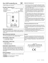
ATTENTION
: Installation must be carried out by an electrician in
compliance with the latest codes and regulations.
ATTENTION
: Disconnect from power source before
installation or service to prevent electric shock.
ATTENTION
: On strobe beacons allow a minimum of 2 minutes
for hazardous high voltage to discharge from unit.
Header Pin settings
for flashing modes.
A
B
C
A
B
C
A
B
C
A
B
C
1Hz Flash (60FPM)
1.5Hz Flash (90FPM)
Double Strike Flash Pattern
CPR FILE DRAWING
No modification permitted
without reference to
"VdS"
~L
~N
Volume
Control
Tone Selection
(See Table)
AC CIRCUIT
S2
SWITCH
+
-
DC CIRCUIT
800/1000 Hz @ 0.25 sec Alternating BS5839 Alarm Tone
500/1200 Hz @ 0.3 Hz 0.5 sec Slow Whoop NEN 2575:2000
544Hz (100mS)/440 Hz (400mS) AFNOR NF S 32-001
800/1000 Hz @ 7 Hz Sweeping
2400/2900 Hz 50 Hz Sweeping
1
2
3
4
5
6
7
8
9
Sawtooth 1200/500 Hz @ 1 Hz - DIN / PFEER P.T.A.P
10
Tone Description
Stage 1
Tone 1
Tone 2
Tone 3
Tone 4
Tone 5
Tone 6
Tone 7
Tone 8*
Tone 9*
Tone 10*
*To set tones 8, 9 & 10
as a first stage
connect terminal 'S2' to
'-' terminal.
800/1000 Hz @ 0.25 sec Alternating BS5839 Alarm Tone
500/1200 Hz @ 0.3 Hz 0.5 sec Slow Whoop NEN 2575:2000
544Hz (100mS)/440 Hz (400mS) AFNOR NF S 32-001
Simulated Bell Sound
Sweeping 800/1000 Hz @ 7 Hz Sweeping
500-1200 Hz 3.75 sec / 0.25 sec Australian Evacuation
Continuous 1000 Hz - PFEER toxic gas
Continuous 554 Hz
420 Hz @ 0.625 sec Australian Alert
1
2
3
4
5
6
7
8
9
Sawtooth 1200/500 Hz @ 1 Hz - DIN / PFEER P.T.A.P
10
8
8
8
1
1
9
10
Tone Description
Stage 1 Stage 2
-
-
-
12V DC and 24V DC Tone Table
115V AC and 230V AC Tone Table
Simulated Bell Sound
Continuous 1000 Hz - PFEER toxic gas
420 Hz @ 0.625 sec Australian Alert
500-1200 Hz 3.75 sec / 0.25 sec Australian Evacuation
99dB(A) @1m
100dB(A) @1m
99dB(A) @1m
97dB(A) @1m
95dB(A) @1m
99dB(A) @1m
100dB(A) @1m
100dB(A) @1m
97dB(A) @1m
97dB(A) @1m
SONF1 dB@ 1m
99dB(A) @1m
100dB(A) @1m
99dB(A) @1m
97dB(A) @1m
100dB(A) @1m
95dB(A) @1m
99dB(A) @1m
100dB(A) @1m
97dB(A) @1m
100dB(A) @1m
Sonora
SONFL1X
Dimensions : 172 x 86 x 83mm
1.5mm² terminals
Cable entry: 1-off M20 x 1.5mm
Temp: -25
C to +55
C
Unit weight: 0.46Kg
B
A
Tel : +44 (0)2 8743 8880 Fax : +44 (0)20 8740 4200
mail : [email protected] web : www.e2s.com
D176-00-501-IS-SC-CPR_SHT1_ISSUE_D
C
NOTE: Please check factory settings and ensure the correct alarm tone is selected for your country or application
Tone Selection / Header Pin Setting - Header pin settings are shown in the tone selection table. The links covered by the jumper
are shown with a black rectangle.
Only tones 1, 2, 3, 4, 8 & 9 have been tested to EN54-3 and are compliant with the Construction Products Regulation 305/2011.
No liability is accepted for any consequences of the use of this document. The technical specification of
this unit is subject to change without notice due to our policy of continual product development. All dimensions/weights
are approximate. This unit is sold subject to our standard conditions of sale, a copy of which is available on request.
SONFL1X Combined Sounder Xenon Beacon
10 Selectable Tones & 2 Stages
5J Xenon Flash Tube
Three Modes: Flashing 1Hz (AC & DC Units),
Flashing 1.5Hz (DC Units Only),
Double Strike (DC Units Only).
Note: Only 1Hz Flashing mode is CPR/VdS approved.
Only 24V dc Version is CPR/VdS Approved.
CE
IP Rating: IP66
Sounder
Voltage Nominal Current Beacon
Order code Range Voltage @Tone 2 Current
SONFL1XDC012[X]/[Y] 10-14V dc 12 V dc 25mA 500mA
SONFL1XDC024[X]/[Y] 20-28V dc 24 V dc 25mA 250mA
SONFL1XAC024[X]/[Y] 24V ± 10% V ac 24 V ac 40mA 300mA
SONFL1XAC115[X]/[Y] 115 ± 10% V ac 115 V ac 13mA 70mA
SONFL1XAC230[X]/[Y] 230 ± 10% V ac 230 V acv 13mA 35mA
[X] Denotes Body Colour,
[Y] Denotes Lens Colour: Note CPR Approved units
only available in C = Clear
Add '-UL' Suffix for UL Approved Units
(Type 4 / 4X / 3R / 13, IP66)
S2 Denotes Stage 2. Stage switches
are customer supplied

warning signals
warning signals
warning signals
warning signals
20
5
CPR FILE DRAWING
No modification permitted
without reference to
"VdS"
INSERT CABLE THROUGH SUITABLY SIZED M20
CABLE GLAND, CUSTOMER SUPPLIED, THEN STRIP
CABLE TO LENGTH.
TORQUE 5Nm
*S2 Denotes Stage 2. Stage switches
are customer supplied
AC
~N
~N
PREWIRED
TO
BEACON
PREWIRED
TO
BEACON
~L
~L
PREWIRED
TO
BEACON
PREWIRED
TO
BEACON
-
+
+
-
S2
DC
S2 SWITCH*
+
-
S2*
DC
~L
~N
AC
D
B
A
D176-00-501-IS-SC-CPR_SHT2_ISSUE_D
1
6
4
2
Dimensions in mm
CONNECT
CABLE AS
SHOWN
Tel : +44 (0)2 8743 8880 Fax : +44 (0)20 8740 4200
mail : [email protected] web : www.e2s.com
3
SONFL1X
Alert Alarm
5
C
TERMINAL
BLOCK
A/C
INPUT
D/C
INPUT
N/A
N/-
N~
-
L/+
L~
+
S2
N/A
SWITCH TO -

warning signals
warning signals
CPR FILE DRAWING
No modification permitted
without reference to
"VdS"
Power
7W
V=55.3m³
Category W-x-y (Wall mounted):
Wall mounted, where x is the maximum
mounting height from the floor and y is the
maximum length of the sides of the square
floor area covered by the VAD.
y
y
x
W-2.4-4.8
Unit
Category W
SONFL1XDC024[x]/C
Coverage Area According to EN54-23
(Only units in the following
table are VdS Approved)
Note: CPR aproved units must be
positioned sounder on top, beacon
below.
A
D176-00-502-IS-SC-CPR_ISSUE_C
B
SONFL1XDC024 HORIZONTAL POLAR PLOT
SONFL1XDC024 VERTICAL POLAR PLOT
SONFL1XDC024 LIGHT OUTPUT
SONFL1XDC024 SOUND PRESSURE LEVEL OUTPUT
Tel : +44 (0)2 8743 8880 Fax : +44 (0)20 8740 4200
mail : [email protected] web : www.e2s.com
(TESTING AT MINIMUM VOLTAGE OF 18V DC. ALL READINGS ARE IN dB(A) @ 1m)
/