
The specifications of this product may vary from this photo and are subject to change without notice.
IRONMAN, IRONMAN TRIATHLON and M-DOT are registeved trademarks of World Triathlon Corporation.
This product is licensed by the IRONMAN TRIATHLON.
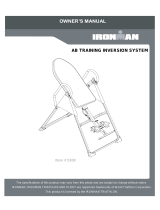
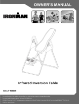
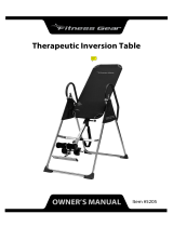
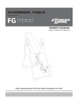
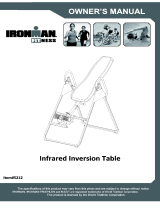
Model 5201
OWNER’S MANUAL
Gravity 1000

SERVICE
To request for product service and order replacement parts, please call our customer
service department at
1-866-924-1688
Monday through Friday, 8:00 am-5:00 pm Pacific Standard Time,
or email at: service@paradigmhw.com
Please have the following information ready when requesting for service:
Your name
Phone number
Owner’s manual
Model number
Serial number
Part number
Date of purchase
*If the product has major defects which prevent it
from functioning properly, please return it to the store of purchase
within the period allowed by the store.
Paradigm Health & Wellness, Inc.
1189 Jellick Ave.
City of Industry, CA 91748
2

Part # Description Quan.
Fax this form to 1-626-810-2166
Or email customer service requests to : service@paradigmhw.com
NAME: ________________________________________________________________
ADRRESS: ______________________________________________________________
TELEPHONE: (day ) ______________________________________________________
(night ) _____________________________________________________
(fax )_______________________________________________________
MODEL #: ______________________________________________________________
PURCHASE DATE: ________________________________________________________
PLACE OF PURCHASE: ____________________________________________________
* YOUR ORDER WILL BE PROCESSED WITHIN 3 BUSINESS DAYS
OFFICIAL USE ONLY
SHIP DATE: _______________________________________________________
TRK # : ___________________________________________________________
BACK ORDER: _____________________________________________________
PART REQUEST FAX FORM
3

Service 2
Part fax request form 3
Safety precautions 5
Overview drawing 6
Part list 7
Included hardware & tools 8
Assembly 9
How to use 13
Storage 16
Maintenance instructions 17
Placement of warning labels 18
TABLE OF CONTENTS
Warm-up 19
Warranty 20
Page #
4

SAFETY PRECAUTIONS
5
This inversion Table was designed and built for optimum safety. However, certain precautions apply
whenever you operate the exercise equipment. Be sure to read the entire manual before assembling
and operating this equipment. Also, please note the following safety instructions:
1. Consult your physician or other health care professionals before using the inversion table.
2. Always wear proper exercise apparel when using the equipment.
3. If any time you feel faint, light-headed or dizziness while operating the equipment, stop exercise
immediately. You should also stop exercising if you are experiencing pain or pressure.
4. Keep children and pets away from the equipment while in use.
5. Only one person should use the equipment at a time.
6. Make sure your equipment is correctly assembled before you use it. Be sure all screws, nuts, and
bolts are tightened prior to use.
7. Do not operate this or any exercise equipment if it is damaged.
8. Watch your body: come up slowly, dizziness after a session means you came up too fast. Wait a
while after eating before using the inversion table. If you get nauseous, come up as soon as you
feel queasy.
9. Always use this equipment on a clear and level surface. Do not use outdoors or near water.
10. Keep hands and feet away from any moving parts. Do not insert any object into any openings.
11. Keep loose clothes, jewelry away from moving parts.
12. WARNING: ALWAYS HOLD ON TO THE SAFETY HANDLES AND GO BACK SLOWLY WHEN
INVERTING. FAILURE TO COMPLY COULD RESULT IN SERIOUS BODILY INJURY.
WARNING:
You should consult with your personal physician to see if inversion equipment is appropriate for you.
This is especially important for people with pre-existing health problems. Do not use this equipment
without your physician's approval.
Do not use this equipment if you have any of the following conditions or ailments:
.Extreme obesity
.Glaucoma, retinal detachment or conjunctivitis
.Pregnancy
.Spinal injury, Cerebral Sclerosis, or acutely swollen joints
.Middle ear infection
.High blood pressure, Hypertension, Recent stroke or Transient Ischemic attack
.Heart or circulatory disorders for which you are being treated
.Hiatus hernia or Ventral hernia
.Bone weaknesses including Osteoporosis, Unhealed fractures, Modularly pins, or Surgically
implanted orthopedic supports.
.Use of anti-coagulants including Aspirin in high doses.
Maximum Weight Capacity is 300 lbs/ 136 kgs.
13. Children under the age of 12 should not use the following fitness equipment.

1
23
4
5
6
7
8
9
39
7
31
31
25
25
22
24
17
18
20
30
12
16
15
1315
11
16
11
16
40
13
13
35
28
26
37
29
43 13
13 15
38 13
36
12
16
1310
15
21
23
32
33
19
19
34
44
46
47
41
42
49
50
52
48
49
50
45
41
27
27
27
27
27
27
13
14
48
51
51
51
48
52
51
48
53
54
9
140
140
147
147
10
10
11
11
150
150
5ff
152
152
1
155
155
158
158
2
3
160
160
4
163
163
5
165
165
6
168
168
7
170
170
8
173
173
9
175
175
10
10
178
178
11
11
180
180
12
12
183
183
185
185
13
13
14
14
188
188
190
190
15
15
16
16
193
193
17
17
195
195
18
18
198
198
19
19
200
200
20
20
203
203
21
21
205
205
22
22
208
208
23
23
210
210
203
203
24
24
205
205
25
25
6
OVERVIEW DRAWING
31
7

PART LIST
Most of the components of the following parts list have already been assembled for your convenience.
Please use the following list as a reference for ordering parts only.
Part # Description Quan. Part # Description Quan.
1 Front U-Frame 1 28
Upper Bed Frame Bushing
1
2 Rear U-Frame 1 29 Handlebar 2
3 Adjustable Boom 1 30 Knob 1
4 Bed Frame 1 31 HRubber eel Holder 4
5 Pivot Arm 2 32 Nylon Strap 1
6 Adjustable lnstep Frame 1 33 Loop Strap 1
7HSteel eel Holder Bracket 4 34 Strap Lock 1
8 Folding Arm 2 35 Nylon Bed 1
9 Rod 1 36 Foam Grip 2
10 Bolt M8*23 2 37 Protective Cover 2
11 Hex Head Bolt M6*47 2 38 Hex Head Bolt M8*23 2
12 Phillips Screw M6*30 4 39 Foot Bar 1
13 Washer Ø20*Ø8.5*1.5 16 40 Hex Head Bolt M8*50 2
14 Round Plate 1 41 Square End Cap 2
15 Lock Nut M8 8 42 Spring Latch 1
16 Lock Nut M6 6 43 Hex Head Bolt M8*38 2
17 Small Spring Knob 1 44 Height Scale 1
18 Large Spring Knob 1 45 Plastic Bushing 1
19 Safety Hook 2 46 Pad 1
20 Rubber Pad 1 47 Double Sided Tape 1
21 Oval End Cap 2 48 Bolt M6*20 4
22 Footbar End Cap 2 49 Right Foot Cap 2
23 Spring 1 50 Left Foot Cap 2
24 Square End Cap 1 51 Bolt M6*25 4
25 Round End Cap 4 52 Washer Ø13*Ø6.5*1.0 8
26
Lower Bed Frame Bushing
2 53 Nut Cap Ø27*Ø13.5 2
27 Washer Ø16*Ø6.5*1.0 8 54 Pivot Arm Ring 2
7

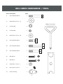
INCLUDED HARDWARE / TOOL
Part # Description Quan.
11 Hex Head Bolt M6*47 2
13 Washer Ø 20 *Ø 8.5 * 1.5 12
15 Lock Nut M8 6
16 Lock Nut M6 2
27 Washer Ø 16 *Ø 6.5 * 1.0 4
38 Hex Head Bolt M8*23 2
40 Hex Head Bolt M8*50 2
43 Hex Head Bolt M8*38 2
48 Bolt M6*20 4
51 Bolt M6*25 4
52 Washer Ø 13 *Ø 6.5 *1 8
53 Nut Cap Ø 27 *Ø 13.5 2
54 Pivot Arm Ring 2
Wrench (2 pcs)
Phillips Screw Driver
8

2
1
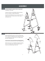
ASSEMBLY
Stand up the base by separating the u-frames. Pull
the Front and Rear U-Frames (1,2) as far apart from
each others as possible.
Then push down on the middle of the two Folding
Arms (8) until they are fully locked down.
Attach the Left & Right Foot Caps (50, 49) to he Front
& Rear U-Frame (1,2) each with two Screws (48,51)
and Washers (52).
Install two Nut Caps (53) onto Lock Nuts (15).
Slide one Protective Cover (37) on to each side of the
base as shown, and pull down on the Protective Covers
(37) until the bottom of the covers are slightly lower
than the Folding Arms (8).
Use the velcro straps on the bottom of the Protective
Covers (37) to secure the covers to the Folding Arms (8).
When the covers are assembled correctly, the Folding
Arms (8) should be fully covered by the Protective
Covers (37) with the logo on the side.
8
2
1
49
50
52
48
49
50 52
51
51
51
48
48
51
48
37
2
1
53
15
53
9

4
5
3
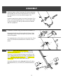
ASSEMBLY
4
5
2
5
5
54
54
5
AB
54
31
7
9
11
16
3
27
27
Slide the bottom of the Pivot Arms (5) into the brackets
that located at each side of the Bed Frame (4), align to
the desired hole on the arm with the peg on the
bracket.
Insert the peg into the hole to lock the Pivot Arms (5) in
place. It is recommended that you use the bottom hole
on the Pivot Arms (5) until you become more familiar
with the equipment.
Install the Pivot Arm Ring (54) onto the Pivot Arms (5).
Mount the Bed Frame (4) to the Rear U-Frame (2) by
inserting the ends of the Pivot Arms (5) into the chan-
nels on the plates.
The slotted portion of the rollers on the end of the Pivot
Arms (5) should be inserted into the channels on the
plates.
Attach one Steel Heel Holder Bracket (7) and one
Rubber Heel Holder (31) to one end of the Rod (9).
Slide the Rod (9) through the large round hole on the
side of Adjustable Boom (3) as shown, and attach the
other Steel Heel Holder Bracket (7) and Rubber Heel
Holder (31) to the other end of the Rod (9).
Secure the Rod (9) on the Adjustable Boom (3) with a
Hex Head Bolt (11), Lock Nut (16), and two Washers
(27).
10

7
8
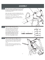
Slide the Foot Bar (39) into the bottom of the
Adjustable Boom (3) and align two of the holes on
the Foot Bar (39) with two holes on the boom.
Secure the Foot Bar (39) in place using two Hex
Head Bolts (40), Lock Nuts (15), and four Wash-
ers (13).
Remove the Square End Cap (41) on the back of
square bracket of Adjustable Boom (3).
Attach the Adjustable Instep Frame (6) to the Adjustable
Boom (3) by inserting the Adjustable Instep Frame (6)
into the square bracket on the boom.
Slide the Adjustable Instep Frame (6) completely into
the square bracket, insert the Hex Head Bolt (11) with a
Washer (27) halfway through the square bracket, slide
the Hex Head Bolt (11) through the ring at the bottom of
the Spring (23), slide the Hex Head Bolt (11) through
the rest of the square bracket, and secure at the other
end with a Washer (27) and Lock Nut (16).
Attach the Square End Cap (41) onto the back of
square bracket of Adjustable Boom (3) that was
removed.
6
ASSEMBLY
6
39
27
40
13
13
15
3
3
17
11
16
6
23
23
16
41
27 11
27
27
Note: To slide the Adjustable Instep Frame (6) into the square frame, you must first pull out the
Small Spring Knob (17)
Pull out the Large Spring Knob (18), and slide the Adjust-
able Boom (3) into the square bracket on the bottom of the
Bed Frame (4) as shown. Slide the Adjustable Boom (3)
upward until the desired height on the Height Scale (44) is
just below the bracket on the bed frame.
Lock the Adjustable Boom (3) in place by releasing the
Large Spring Knob (18) and sliding the Adjustable Boom (3)
up or down slightly until the Large Spring Knob (18) "pops"
down into the locked position.
For added safety, secured the Knob (30) into the back side
of the bracket on the Bed Frame (4).
4
44
3
30
18
17 195
18 198
19200
20203
21205
22208
23 210
203
24
205
25
11

9
10
11
Attach the top end of Handlebar (29) onto the Rear
U-Frame (2) and Pivot Arm Reinforcement Plate
(54) with one Hex Head Bolt (38), Lock Nut (15),
and two Washers (13).
Attach the bottom end of the Handlebar (29) onto
the Rear U-Frame (2) with one Hex Head Bolt (43),
Lock Nut (15), and two Washers (13).
Repeat above same steps to attach the other
Handlebar (29) onto the Rear U-Frame (2) and
Pivot Arm Ring (54).
ASSEMBLY
13
15
29
43
13 13
15
38
13
2
54
Attach the Nylon Strap (32) to the
Strap Lock (34) by inserting the end
of the Nylon Strap (32) up through
the bottom of the Strap Lock (34),
loop the Nylon Strap (32) over the
Pre-assembled Loop Strap (33) and
down through the Strap Lock (34).
Now, loop the strap back over itself,
and insert back through the Strap
Lock (34), and pull tight to secure.
Attach the Nylon and Loop Straps (32,33)
to the Inversion Table by hooking the end of
the Nylon Strap (32) to the pre-assembled
loop on the back of the Bed Frame (4) as
shown.
Hook the other end of Loop Strap (33) to
the other Pre-assembled loop on the Front
U-Frame (1) as shown. 34
33
1
4
19
19
12
19 3433 32 19
19 33 34 32 19

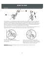
HOW TO USE
Pivot Arm
Pivot arm is NOT aligned correctly.
The pivot arm is not inserted all the way into
the curved slot.
The Pivot Arms (5) can be adjusted to allow for a greater or lesser degree of inversion. To adjust the
Pivot Arms (5) simply pull out on them until the post is out of the hole, slide them up or down to the
desired hole, push in until the post goes through the desired hole, The bottom hole provides the least
amount of inversion, while the top hole provides the greatest amount, It is recommended that begin-
ners use the bottom hole until they are familiar with the inversion table.
NOTE: Both Pivot Arms (5) must be adjusted to the same hole. Trying to adjust the Pivot Arms (5) on
two different positions could cause damage to the inversion table, or injury to the user.
Make sure the pivot arm is inserted all the
way into the slot. Pivot arm is aligned correctly
when the groove sits directly on the curved slot
and the pivot arm is able to rotate freely.
WARNING: Make sure both pivot arms are in the same hole to prevent serious
injury from occurring.
13

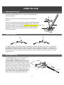
HOW TO USE
Balaning the inversion table
The inversion table is like a very sensitively balanced fulcrum. It responds to very slight changes in
weight distribution. So, it is very important to make sure that the height is adjusted properly. To do this,
mount the inversion table, lock your ankles into the heel holders, and lie back with your hands at your
sides. Slowly place you hands across you chest. While in this position, your head should still be
above our feet. If your feet are above your head, dismount and adjust the height again.
Using the inversion table
1. Start by lying fully back on the bed with your hands at your side, or resting on your thighs.
2. Keeping your hands close to your body begin to raise your arms slowly allowing the table to
rotate backward. Stop, or lower your arms to control the downward rotation of the table.
3. Raise your arms until they are over your head. At this point, the inversion table will be as far
back as it can go.
4. As you get more comfortable with the use, rock the bed slowly by moving your arms up and
down slowly.
5. It is recommended that the inversion table be used for five or ten minutes each morning, and
again each evening.
6. Return to the upright position by slowly moving your hands back down to your thighs.
Suggestion for use
1. Begin slowly: invert only 15~20 degrees to begin with. Stay inverted only as long as you are
comfortable. Return upright slowly.
2. Make gradual changes: increase the angle only if it is comfortable. Increase angle only a few
degrees at a time. Increase the time of use 1~2 minutes up to ten over a period of weeks. Add
stretching and light exercise only after you are comfortable with inversion.
3. Watch your body: come up slowly, dizziness after a session means you came up to fast. Wait a
while after eating before using table. If you get nauseous, do not fight it, come up as soon as
you feel queasy.
4. Keep moving: movement while inverted encourages blood, circulation. Movement may be
accomplished by either rhythmic traction or light exercise. Do not exercise strenuously while
inverted, Limit partial inversion without movement to one or two minutes. Limit full inversion
with no movement to only a few seconds.
5. Invert regularly: we recommend two or three times a day depending upon your current
condition. Try to schedule it for the same times each day.
14

HOW TO USE
Strap adjustment
Adjusting ankle holder
Adjusting the boom
For added safety, a nylon strap has been included to restrict the degree of inversion. This strap can
be adjusted to different lengths to allow for a greater or lesser degree of inversion. To lengthen the
Nylon Strap (32) feed the top end of Nylon Strap (32) into the strap lock, and pull on the lower end of
the strap. To shorten the length feed the bottom end of Nylon Strap (32) into the strap lock, and pull
on the top end.
Pull up the Small Spring Knob (17), slide the Adjustable Instep
Frame (6) upward
Stand on the foot-bar located at the bottom of the Adjustable
Boom (3).
Pull up on the Small Spring Knob (17), allow the Adjustable instep
frame (6) to slide back into the Adjustable Boom (3). Push in the
Adjustable Instep Frame (6) until the Rubber Heel Holders (31) are around
your ankles. Release the Small Spring Knob (17) and adjust the
Adjustable instep frame (6) slightly until the Small Spring Knob
(17) locks into place.
The Adjustable Boom (3) can be moved to a
variety of different positions, in order to
accommodate the height of the person on the
inversion table. To adjust the boom loosen the
knob (30), pull out the Large Spring Knob (18),
and slide the boom up or down until the desired
height on the Height Scale (44) is positioned just
below the Square Bushing (26). When the boom
is in the desired position, simply release the
Large Spring Knob (18), slide the boom slightly
up or down until the Large Spring Knob (18)
locks into place, and tighten the Knob (30).
17
6
3
31
15
4
18
30
44
32 32

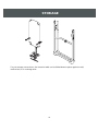
STORAGE
For your storage convenience, the inversion table can be folded down to place against a wall,
under a bed, or in a storage area.
16

MAINTENANCE INSTRUCTIONS
You should check your INVERSION TABLE for any kind of wear and tear before every use.
1. Check the pivot arms, nylon bed, heel holder brackets,
nylon straps, and the strap buckle for wear and tear.
2. Replace damaged and worn components immediately.
3. Please keep all damaged equipment out of use until it is repaired.
17

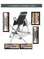
PLACEMENT OF WARNING LABELS
18

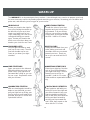
WARM-UP
The WARM-UP is an important part of any workout. It should begin every session to prepare your body
for more strenuous exercise by heating up and stretching your muscles, increasing your circulation and
pulse rate, and delivering more oxygen to your muscles.
HEAD ROLLS
Rotate your head to the right for
one count, feeling the stretch up
the left side of your neck, then
rotate your head back for one
count, stretching your chin to the
ceiling and letting your mouth
open. Rotate your head to the
left for one count, then drop your
head to your chest for one count.
SHOULDER LIFTS
Lift your right shoulder to ward
your ear for one count. Then lift
your left shoulder up for one
count as you lower your right
shoulder.
SIDE STRETCHES
Open your arms to the side and
lift them until they are over your
head. Reach your right arm as
far toward the ceiling as you can
for one count. Repeat this action
with your left arm.
QUADRICEPS STRETCH
With one hand against a wall for
balance, reach behind you and
pull your right foot up. Bring your
heel as close to your buttocks as
possible. Hold for 15 counts and
repeat with left foot.
INNER THIGH STRETCH
Sit with the soles of your feet
together and your knees point-
ing outward. Pull your feet as
close to your groin as possible.
Gently push your knees toward
the floor. Hold for 15 counts.
TOE TOUCHES
Slowly bend forward from your
waist, letting your back and
shoulders relax as you stretch
toward your toes. Reach as
far as you can and hold for 15
counts.
HAMSTRING STRETCHES
Extend your right leg. Rest the
sole of your left foot against
your right inner thigh. Stretch
toward your toe as far as
possible. Hold for 15 counts.
Relax and then repeat with left
leg.
CALF/ACHILLES STRETCH
Lean against a wall with your
left leg in front of the right and
your arms forward. Keep your
right leg straight and the left
foot on the floor; then bend the
left leg and lean forward by
moving your hips toward the
wall. Hold, then repeat on the
other side for 15 counts.
19

ONE YEAR LIMITED WARRANTY
20
Paradigm Inc. warrants to the original purchaser that this product is free from defects in
material and workmanship when used for the purpose intended, under the conditions
that it has been installed and operated in according to Paradigm's Owner's Manual.
Paradigm's obligation under this warranty is limited to replacing or of charge, any parts
which may prove to be defective under normal home use. This warranty does not
include any damage caused by improper operation, misuse or commercial application.
From the date of purchase, the frame is warranted to be free from defects for 1 (one)
year. All parts and workmanship, including inversion components, upholstery, and
hardware are to be free from defects for 90 days. This warranty is offered only to the
original owner and is not transferable. Proof of purchase is required.
-
 1
1
-
 2
2
-
 3
3
-
 4
4
-
 5
5
-
 6
6
-
 7
7
-
 8
8
-
 9
9
-
 10
10
-
 11
11
-
 12
12
-
 13
13
-
 14
14
-
 15
15
-
 16
16
-
 17
17
-
 18
18
-
 19
19
-
 20
20


Ironman Fitness 54201 Owner's manual
- Type
- Owner's manual
- This manual is also suitable for
Ask a question and I''ll find the answer in the document
Finding information in a document is now easier with AI
Related papers

Other documents
-
 Ironman 5208 Owner's manual
-
 Ironman 5216 Owner's manual
-
 Ironman 5201 Owner's manual
-
 Ironman 5211 Owner's manual
-
 Fitness Gear 5205 Owner's manual
-
LifeGear 75118 Inversion table Owner's manual
-
 Fitness Gear 5226 Owner's manual
-
 Ironman 5212 Owner's manual
-
 Ironman 5502 Owner's manual
-
 Ironman 5501 Owner's manual


