Page is loading ...

SERVICE MANUAL
LN-9221-00.7
(Replaces LN-9221-00.6)
March - 2013
MODEL: LREG5001
IMPORTANT: Before using this equipment, careful-
ly read SAFETY PRECAUTIONS, starting on page
1, and all instructions in this manual. Keep this
Service Manual for future reference.
DR-1TM PLASTIC FLUID REGULATOR
Service Manual Price: $20.00 (U.S.)
Ransburg

NOTE: This manual has been changed from revision LN-9221-00.6 to revision LN-9221-00.7.
Reasons for this change are noted under “Manual Change Summary” inside the back
cover of this manual.
DR-1 Plastic Fluid Regulator Ransburg
LN-9221-00.7

TOOLS REQUIRED ..............................................................................................................9
PRELIMINARY PROCEDURES ............................................................................................9
DISASSEMBLY PROCEDURES ...........................................................................................9
REGULATOR CROSS-SECTIONAL VIEW ...........................................................................10
ASSEMBLY PROCEDURES .................................................................................................11
TEST PROCEDURES ...........................................................................................................12
PREVENTIVE MAINTENANCE .............................................................................................12
TROUBLESHOOTING GUIDE ..............................................................................................13
SAFETY: 1-5
SAFETY PRECAUTIONS ......................................................................................................1
HAZARDS / SAFEGUARDS ..................................................................................................2-5
PAGE
INTRODUCTION: 6-12
CONTENTS
FEATURES ............................................................................................................................6
SPECIFICATIONS .................................................................................................................6
DR-1 FLOW VS. SIGNAL PRESSURE .................................................................................7
OPERATION: 8
OPERATION ..........................................................................................................................8
MAINTENANCE: 9-13
PARTS IDENTIFICATION: 14-16
REGULATOR CROSS-SECTIONAL VIEW / PARTS LIST ................................................... 14-15
RECOMMENDED SPARE PARTS ....................................................................................... 16
SERVICE KITS ...................................................................................................................... 16
WARRANTY POLICIES: 17
LIMITED WARRANTY ...........................................................................................................17
DR-1 Plastic Fluid Regulator - Contents
Ransburg
LN-9221-00.7

W A R N I N G
!
W A R N I N G
!
SAFETY
SAFETY PRECAUTIONS
Before operating, maintaining or servicing any
Ransburg electrostatic coating system, read and
understand all of the technical and safety liter-
ature for your Ransburg products. This manual
contains information that is important for you to
know and understand. This information relates to
USER SAFETY and PREVENTING EQUIPMENT
PROBLEMS. To help you recognize this informa-
tion, we use the following symbols. Please pay
particular attention to these sections.
A WARNING! states information to alert you
to a situation that might cause serious injury
if instructions are not followed.
A CAUTION! states information that tells how
to prevent damage to equipment or how to
avoid a situation that might cause minor injury.
A NOTE is information relevant to the proce-
dure in progress.
While this manual lists standard specications
and service procedures, some minor deviations
may be found between this literature and your
equipment. Differences in local codes and plant
requirements, material delivery requirements,
etc., make such variations inevitable. Compare
this manual with your system installation draw-
ings and appropriate Ransburg equipment man-
uals to reconcile such differences.
Careful study and continued use of this manual will
provide a better understanding of the equipment
and process, resulting in more efcient operation,
longer trouble-free service and faster, easier
troubleshooting. If you do not have the manuals
and safety literature for your Ransburg system,
contact your local Ransburg representative or
Ransburg.
The hazards shown on the following pag-
es may occur during the normal use of this
equipment. Please read the hazard chart be-
ginning on page 2.
The user MUST read and be familiar with
the Safety Section in this manual and the
Ransburg safety literature therein identied.
This manual MUST be read and thor-
oughly understood by ALL personnel who
operate, clean or maintain this equipment!
Special care should be taken to ensure that
the WARNINGS and safety requirements for
operating and servicing the equipment are
followed. The user should be aware of and
adhere to ALL local building and re codes
and ordinances as well as NFPA-33 SAFE-
TY STANDARD, LATEST EDITION, prior
to installing, operating, and/or servicing this
equipment.
DR-1 Plastic Fluid Regulator - Safety Ransburg
1 LN-9221-00.7

Spray Area
AREA
Tells where hazards
may occur.
HAZARD
Tells what the hazard is.
SAFEGUARDS
Tells how to avoid the hazard.
Improper or inadequate
operation and maintenance
procedures will cause a re
hazard.
Protection against inadver-
tent arcing that is capable of
causing re or explosion is
lost if any safety interlocks
are disabled during opera-
tion. Frequent Power Supply
or Controller shutdown indi-
cates a problem in the system
requiring correction.
Fire extinguishing equipment must be present in
the spray area and tested periodically.
Spray areas must be kept clean to prevent the
accumulation of combustible residues.
Smoking must never be allowed in the spray
area.
The high voltage supplied to the atomizer must
be turned off prior to cleaning, ushing or main-
tenance.
When using solvents for cleaning:
•Those used for equipment ushing should
have ash points equal to or higher than
those of the coating material.
•Those used for general cleaning must have
ash points above 100°F (37.8°C).
Spray booth ventilation must be kept at the rates
required by NFPA-33, OSHA, country, and local
codes. In addition, ventilation must be main-
tained during cleaning operations using am-
mable or combustible solvents.
Electrostatic arcing must be prevented. Safe
sparking distance must be maintained between
the parts being coated and the applicator. A dis-
tance of 1 inch for every 10KV of output voltage
is required at all times.
Test only in areas free of combustible material.
Testing may require high voltage to be on, but
only as instructed.
Non-factory replacement parts or unautho-
rized equipment modications may cause re or
injury.
If used, the key switch bypass is intended for
use only during setup operations. Production
should never be done with safety interlocks dis-
abled.
Never use equipment intended for use in water-
borne installations to spray solvent based ma-
terials.
The paint process and equipment should be
set up and operated in accordance with NFPA-
33, NEC, OSHA, local, country, and European
Health and Safety Norms.
DR-1 Plastic Fluid Regulator - Safety
Ransburg
2
LN-9221-00.7

AREA
Tells where hazards
may occur.
HAZARD
Tells what the hazard is.
SAFEGUARDS
Tells how to avoid the hazard.
Spray Area
Improper operation or mainte-
nance may create a hazard.
Personnel must be properly
trained in the use of this equip-
ment.
Explosion Hazard
Improper or inadequate oper-
ation and maintenance proce-
dures will cause a re hazard.
Protection against inadvertent
arcing that is capable of caus-
ing re or explosion is lost if
any safety interlocks are dis-
abled during operation.
Frequent Power Supply or
Controller shutdown indicates
a problem in the system requir-
ing correction.
General Use and
Maintenance
Electrostatic arcing must be prevented. Safe
sparking distance must be maintained between
the parts being coated and the applicator. A dis-
tance of 1 inch for every 10KV of output voltage
is required at all times.
Unless specically approved for use in hazard-
ous locations, all electrical equipment must be
located outside Class I or II, Division 1 or 2
hazardous areas, in accordance with NFPA-33.
Test only in areas free of ammable or combus-
tible materials.
The current overload sensitivity (if equipped)
MUST be set as described in the correspond-
ing section of the equipment manual. Protec-
tion against inadvertent arcing that is capable
of causing re or explosion is lost if the current
overload sensitivity is not properly set. Fre-
quent power supply shutdown indicates a prob-
lem in the system which requires correction.
Always turn the control panel power off prior to
ushing, cleaning, or working on spray system
equipment.
Before turning high voltage on, make sure no
objects are within the safe sparking distance.
Ensure that the control panel is interlocked with
the ventilation system and conveyor in accor-
dance with NFPA-33, EN 50176.
Have re extinguishing equipment readily avail-
able and tested periodically.
Personnel must be given training in accordance
with the requirements of NFPA-33, EN 60079-0.
Instructions and safety precautions must be
read and understood prior to using this equip-
ment.
Comply with appropriate local, state, and na-
tional codes governing ventilation, re protec-
tion, operation maintenance, and housekeep-
ing. Reference OSHA, NFPA-33, EN Norms
and your insurance company requirements.
DR-1 Plastic Fluid Regulator - Safety Ransburg
3 LN-9221-00.7

AREA
Tells where hazards
may occur.
HAZARD
Tells what the hazard is.
SAFEGUARDS
Tells how to avoid the hazard.
Spray Area /
High Voltage
Equipment
Electrical Discharge
There is a high voltage device
that can induce an electrical
charge on ungrounded objects
which is capable of igniting
coating materials.
Inadequate grounding will
cause a spark hazard. A
spark can ignite many coating
materials and cause a re or
explosion.
Parts being sprayed and operators in the spray
area must be properly grounded.
Parts being sprayed must be supported on con-
veyors or hangers that are properly ground-
ed. The resistance between the part and earth
ground must not exceed 1 meg ohm. (Refer to
NFPA-33.)
Operators must be grounded. Rubber soled in-
sulating shoes should not be worn. Grounding
straps on wrists or legs may be used to assure
adequate ground contact.
Operators must not be wearing or carrying any
ungrounded metal objects.
When using an electrostatic handgun, operators
must assure contact with the handle of the ap-
plicator via conductive gloves or gloves with the
palm section cut out.
NOTE: REFER TO NFPA-33 OR SPECIFIC
COUNTRY SAFETY CODES REGARDING
PROPER OPERATOR GROUNDING.
All electrically conductive objects in the spray
area, with the exception of those objects re-
quired by the process to be at high voltage, must
be grounded. Grounded conductive ooring
must be provided in the spray area.
Always turn off the power supply prior to ush-
ing, cleaning, or working on spray system equip-
ment.
Unless specically approved for use in hazard-
ous locations, all electrical equipment must be
located outside Class I or II, Division 1 or 2 haz-
ardous areas, in accordance with NFPA-33.
DR-1 Plastic Fluid Regulator - Safety
Ransburg
4
LN-9221-00.7

Toxic Substances Certain material may be harmful
if inhaled, or if there is contact
with the skin.
Follow the requirements of the Material Safety
Data Sheet supplied by coating material manu-
facturer.
Adequate exhaust must be provided to keep the
air free of accumulations of toxic materials.
Use a mask or respirator whenever there is a
chance of inhaling sprayed materials. The mask
must be compatible with the material being
sprayed and its concentration. Equipment must
be as prescribed by an industrial hygienist or
safety expert, and be NIOSH approved.
AREA
Tells where hazards
may occur.
HAZARD
Tells what the hazard is.
SAFEGUARDS
Tells how to avoid the hazard.
Electrical
Equipment
Electrical Discharge
High voltage equipment is uti-
lized in the process. Arcing
in the vicinity of ammable or
combustible materials may oc-
cur. Personnel are exposed to
high voltage during operation
and maintenance.
Protection against inadvertent
arcing that may cause a re or
explosion is lost if safety circuits
are disabled during operation.
Frequent power supply shut-
down indicates a problem in the
system which requires correc-
tion.
An electrical arc can ignite coat-
ing materials and cause a re or
explosion.
Unless specically approved for use in hazard-
ous locations, the power supply, control cabinet,
and all other electrical equipment must be locat-
ed outside Class I or II, Division 1 and 2 hazard-
ous areas in accordance with NFPA-33 and EN
50176.
Turn the power supply OFF before working on
the equipment.
Test only in areas free of ammable or combus-
tible material.
Testing may require high voltage to be on, but
only as instructed.
Production should never be done with the safety
circuits disabled.
Before turning the high voltage on, make sure no
objects are within the sparking distance.
Explosion Hazard –
Incompatible Materials
Halogenated hydrocarbon sol-
vents for example: methylene
chloride and 1,1,1,-Trichlo-
roethane are not chemically
compatible with the aluminum
that might be used in many sys-
tem components. The chemical
reaction caused by these sol-
vents reacting with aluminum
can become violent and lead to
an equipment explosion.
Aluminum is widely used in other spray appli-
cation equipment - such as material pumps,
regulators, triggering valves, etc. Halogenated
hydrocarbon solvents must never be used with
aluminum equipment during spraying, ushing,
or cleaning. Read the label or data sheet for the
material you intend to spray. If in doubt as to
whether or not a coating or cleaning material is
compatible, contact your coating supplier. Any
other type of solvent may be used with aluminum
equipment.
Spray Area
DR-1 Plastic Fluid Regulator - Safety Ransburg
5 LN-9221-00.7

INTRODUCTION
SPECIFICATIONS
Air Pressures: Variable by Control
(Manual or Automatic)
Fluid Input: 100 psi (6.8 bar max.)
(10 psi minimum above
output pressure)
Fluid Output: Variable by Ratio
Pneumatic / Fluid Connections
Air Pilot: 1/8-inch NPT x 1/4-inch
Tube (Low and High)
Fluid In: 7/16-20 UNF - 37° Flare
1/4-inch OD Tube, use
LSFI0022-04, Fitting
3/8-inch OD Tube, use
LSFI0022-07, Fitting
Fluid Out: 1/8-inch NPT
1/4-inch OD Tube, use
LSFI0041-01, Fitting
3/8-inch OD Tube, use
LSFI0041-02, Fitting
Volume of Paint
Held Within
Regulator: 5 cc
Mechanical
Height: 4-1/2-inch (114mm)
w/ttings
Diameter: 4-inch (102mm)
w/ttings
Environmental / Physical
FEATURES
• Two independently controlled ow pressure
ranges.
• High ow range port for higher uid deliveries.
• Low ow range for more precise control over
lower uid deliveries.
• Interchangeable low ow ratios (1:1, 1:2, 1:3,
1:4, 1:6, 1:8, 1:10) for precise control.
• Plastic and coated wetted parts for
decreased color change time.
• Factory Mutual listed in conjunction with the
Aerobell 33TM.
DR-1 Plastic Fluid Regulator - Introduction
Ransburg
6
LN-9221-00.7

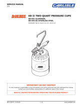
DR-1 FLOW VS SIGNAL PRESSURE
Viscosity=40 sec
Zahn #2
15 ft 1/4 in ID tubing
.093 orice
HIGH
FLOW
1:2 1:1
1:3 1:4
1:6 1:8
1:10
Viscosity=25 sec
Zahn #2
15 ft 1/4 in ID tubing
.093 orice
HIGH
FLOW
1:2 1:1
1:3 1:4
1:6 1:8
1:10
DR-1 Plastic Fluid Regulator - Introduction Ransburg
7 LN-9221-00.7

OPERATION
The DR-1TM plastic regulator is designed to pro-
vide remote control uid regulation for automatic
coating applications.
The regulator features two independently control-
lable ow pressure ranges from the uid output
port. The high ow range port accom-modates
higher uid deliveries and minimal color change
times. The lower ow ranges provide precise uid
delivery control. There are seven lower range
models available (1:1, 1:2, 1:3, 1:4, 1:6, 1:8, and
1:10) which can be selected based on the required
uid ow rate.
Separate pilot signals modulate each of the regu-la-
tor’s two diaphragms to control the amount of paint
being delivered from the regulator to the spray
applicator. These pilot signals can be controlled
manually or automatically with Ransburg closed
loop ow control systems.
Because of the regulator’s dual range capabilities,
it provides the user exibility of selecting either
the high ow range or the low ow range. Differ-
ent coating material viscosities and quick color
change requirements may necessitate the use of
both ranges. If color change time is not a factor
or if material viscosity remains relatively constant,
either port may be used depending on ow rate
requirements. All regulators, regardless of ratio
designation, have the high ow port.
The low ow (i.e. 1:2, 1:4, etc.) port provides a
lower, more precise ow response curve. Fluid
output, as a result, is less likely to be affected by
pilot signal errors. An increase in the ratio (i.e. from
1:2 to 1:4) provides a lower slope in the ow/air
signal pressure curve, but, more precise response
curve. This same increase in ratio, however, will
reduce ow capacity and should be considered
when selecting the proper regulator ratio.
The following factors must then be considered
when selecting the regulator ratio required for
proper uid control:
• Fluid tubing inside diameter (ID) and length
• Fluid feed tube inside diameter (ID) and length
• Fluid viscosity
• Fluid input pressures
Preliminary testing will determine which regulator
ratio should be used. If conditions change after
installation which require a different low ow ratio,
this regulator can be altered easily by replacing
the existing ratio spacer ring and upper retainer
with the desired ratio (ratio designation is etched
on the side of the spacer ring).
W A R N I N G
NEVER wrap the applicator, associated
valves and tubing, and supporting hardware
in plastic to keep it clean. A surface charge
may build up on the plastic surface and dis-
charge to the nearest grounded object. Ef-
ciency of the applicator will also be reduced
and damage or failure of the applicator com-
ponents may occur. WRAPPING THESE
COMPONENTS IN PLASTIC WILL VOID
WARRANTY.
!
DR-1 Plastic Fluid Regulator - Operation
Ransburg
8
LN-9221-00.7

MAINTENANCE
PRELIMINARY
PROCEDURES
Prior to removing the regulator for service or
repair, perform the following:
1. If possible, ush the regulator with suitable
cleaning solvent.
2. Turn the uid and air "OFF" to the regulator
and disconnect the air and uid lines from the
regulator.
3. Remove the regulator for service.
DISASSEMBLY
PROCEDURES
(Refer to Figure 1)
TOOLS REQUIRED
• 3/4" Open End Wrench
• Adjustable Wrench
• Screwdriver
• Repair Kit, 73913-00
1. Remove Item 4 (8-screws) holding the regu-
lator assembly together with the screwdriver.
4. Separate Item 6 (lower diaphragm retainer),
Item 10 (o-ring), item 8 (lower diaphragm), Item
17 (bleed spacer), Item 14 (center diaphragm)
and, Item 5 (upper diaphragm retainer) from the
spacer ring assembly.
5. With the 3/4" open end wrench, remove Item
13 (retaining plug), Item 12 (spring) and, Item 11
(regulating needle) from Item 3 (lower housing).
6. Remove Item 11 (regulating seat) and Item 10
(o-ring) from the lower housing assembly.
7. Clean all metal parts with suitable cleaning
solvent. DO NOT use solvent on the diaphragms
or o-rings.
2. Remove item 1 (cap), item 9 (diaphragm), spac-
er ring assembly and the lower housing assembly.
3. With screwdriver, remove Item 16 (screw) from
the spacer ring assembly.
Care MUST be taken while cleaning
the coated parts of the regulator to prevent
scratching.
C A U T I O N
!
When separating parts it may be neces-
sary to use a small screwdriver. Care should
be taken to NOT damage the plastic compo-
nents. Damage of these parts may cause
leakage.
C A U T I O N
!
Unless replacing the cap or spacer
ring, it is NOT necessary to remove the air
ttings.
The regulating needle and seat are a
matched set with matching serial num-
bers. Care must be taken to not use nee-
dles and seats with non-matching serial
numbers as uid leakage may occur. If
either component needs to be replaced, a
new matched set must be used.
NOTE
DR-1 Plastic Fluid Regulator - Maintenance Ransburg
9 LN-9221-00.7

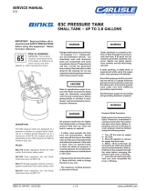
Figure 1: Regulator Cross-Sectional View
DR-1 Plastic Fluid Regulator - Maintenance
Ransburg
10
LN-9221-00.7

ASSEMBLY PROCEDURES
(Refer to Figure 1)
1. Place Item 10 (o-ring) in the slot on Item 6
(lower diaphragm retainer).
2. Place Item 8 (lower diaphragm) on the lower
diaphragm retainer with the side of the diaphragm
contacting the retainer (o-ring side).
3. Stack the following parts on the lower dia-
phragm, in the following order:
• Item 7 (Center Diaphragm Retainer)
• Item 17 (Bleed Spacer)
• Item 14 (Center Diaphragm)
• Item 5 (Upper Diaphragm Retainer)
• Item 16 (Screw)
4. Ensure that clearance holes in Items 8 and
14 (diaphragms) and Item 17 (bleed spacer) are
aligned properly and tighten Item 16 (screw). Use
adhesive 222 on screw threads. Set this assembly
aside.
5. Place lower housing on table with bottom
threaded opening facing "UP".
6. Insert Item 10 (o-ring) and Item 11 (regulating
seat) into the lower housing. The beveled side
of the regulating seat must be "UP".
8. Place Item 10 (o-ring) on Item 13 (retaining
plug).
9. Place Item 12 (spring) into lower housing over
Item 11 (regulating needle) and thread Item 13
(retaining plug) into lower housing. Tighten Item
13 (retaining plug) ensuring that needle/spring
remains in the center of the lower housing.
10. Place lower housing on table with bowl facing
"UP" and place diaphragm assembly (from step 4),
with pin facing "DOWN". Rotate the diaphragm
assembly so that the slot on Item 6 (lower retainer)
is 180o to the outlet port on the lower housing for
cleaner ushing of paint.
11. Place Item 2 (spacer ring) on the top of the
diaphragm assembly with largest opening facing
"DOWN". Rotate the spacer ring, without rotating
the diaphragm assembly, so that the inlet port of
the spacer ring is 90o to the outlet port on the lower
housing and all the clearance holes are aligned
(see Figure 1).
12. Place Item 9 (diaphragm) on Item 2 (spacer
ring) and align holes.
13. Place Item 1 (cap) on diaphragm. Rotate
the cap, without rotating the diaphragm assembly,
so that the inlet port of the cap is 90o from Item
2 (spacer ring) and 180o from the outlet port on
the lower housing. Align holes and insert Item 4
(8-screws).
14. Tighten opposing screws alternately to 8
lbs•in, ensuring uniform sealing of the diaphragms.
Then follow by tightening each screw in a circle
pattern to 14-16 lbs•in.
7. Place Item 11 (regulating needle) into lower
housing with the ball end against Item 11 (regu-
lating seat).
Verify regulator seat and needle have
matching serial numbers.
C A U T I O N
!
DO NOT overtighten the air ttings.
Overtightening the ttings may cause the
stem of the tting to snap off.
C A U T I O N
!
DO NOT scratch the coating.
C A U T I O N
!
DR-1 Plastic Fluid Regulator - Maintenance Ransburg
11 LN-9221-00.7

TEST PROCEDURES
(Refer to Figure 1)
After repair is complete, test the regulator in the
following manner:
1. Set air and uid regulators to zero and attach
air and uid lines to the regulator.
2. Gradually increase air pressure to the regulator
to 80 psi, visually checking for leaks. Tighten
Item 4 (screws) if leakage occurs.
3. Set air regulator to zero. Gradually increase
uid pressure to 80 psi, visually checking for
leakage. Clean or replace Item 11 (needle and
seat) if leakage at outlet port.
NOTES
4. Gradually increase air pressure on either of the
air lines and visually observe a gradual increase
in uid ow. If regulator does not perform sat-
isfactorily, inspect components for damage and
replace where required.
PREVENTIVE
MAINTENANCE
1. Rebuild with 73913, repair kit, and 74160-00,
needle and seat, at 6 months minimum, 12 months
maximum.
2. Retorque (8) screws at the following intervals:
- 2 days after rebuild
- Immediately before installation
- 6 month intervals
If water or solvent is used for testing, it
is normal for minor leakage to occur at the
uid output port, due to the low viscosities
of these uids.
NOTE
DR-1 Plastic Fluid Regulator - Maintenance
Ransburg
12
LN-9221-00.7

TROUBLESHOOTING GUIDE
General Problem Cause Solution
No Flow
Will Not Shut Off
Paint Leakage
Air Leakage
Inconsistent Flow
1. Plugged inlet
2. Item 11 (Needle and
seat) stuck
3. No pilot air
1. Item 11 (Needle and
seat) dirty
2. Pilot air not shut off
1. Item 4 (screws) loose
2. Ruptured Item 8 (lower
diaphragm)
3. Loose uid ttings
4. Pinched Item 10 (o-ring)
1. Loose air tting
2. Item 4 (screws) loose
3. Ruptured Item 14 (cen-
ter diaphragm)
1. Incorrect regulator ratio
used
2. Diaphragm stretched
from excessive air pres
sure
3. Ruptured Item 9 (upper
diaphragm)
4. Inconsistent air pilot
sup- ply
5. Low inlet uid pressure
1. Flush clean
2. Remove and clean or replace
3. Check air pilot
1. Remove and clean or replace
2. Check air supply
1. Tighten per "Assembly Procedures"
2. Rebuild regulator
3. Tighten
4. Replace
1. Tighten
2. Tighten per "Assembly Procedure"
3. Rebuild regulator
1. Refer to "Operation" section for correct
sizing information
2. Rebuild regulator
3. Rebuild regulator
4. Check air source
5. Inlet pressure must be at least 10 psi
above outlet pressure, 100 psi maximum
DR-1 Plastic Fluid Regulator - Maintenance Ransburg
13 LN-9221-00.7

Figure 2: Regulator Cross-Sectional View
PARTS IDENTIFICATION
DR-1 Plastic Fluid Regulator - Parts Identication
Ransburg
14
LN-9221-00.7

DR-1 Regulator Assembly Select Options Below
Ratio 1:1 (1/4-inch Tube) LREG5001-01
Ratio 1:2 (1/4-inch Tube) LREG5001-02
Ratio 1:3 (1/4-inch Tube) LREG5001-03
Ratio 1:4 (1/4-inch Tube) LREG5001-04
Ratio 1:6 (1/4-inch Tube) LREG5001-06
Ratio 1:8 (1/4-inch Tube) LREG5001-08
Ratio 1:10 (1/4-inch Tube) LREG5001-10
Ratio 1:1 (3/8-inch Tube) LREG5001-11
Ratio 1:2 (3/8-inch Tube) LREG5001-12
Ratio 1:3 (3/8-inch Tube) LREG5001-13
Ratio 1:4 (3/8-inch Tube) LREG5001-14
Ratio 1:6 (3/8-inch Tube) LREG5001-16
Ratio 1:8 (3/8-inch Tube) LREG5001-18
Ratio 1:10 (3/8-inch Tube) LREG5001-20
1 Cap LREG0004-01 1
2 Spacer Ring, For: Select Options Below 1
Ratio 1:1 LREG0003-01
Ratio 1:2 LREG0003-02
Ratio 1:3 LREG0003-03
Ratio 1:4 LREG0003-04
Ratio 1:6 LREG0003-06
Ratio 1:8 LREG0003-08
Ratio 1:10 LREG0003-10
3 Lower Housing LREG0001 1
4 Screw, Slotted LSFA0015-00 8
5 Upper Diaphragm Retainer, For: Select Options Below 1
Ratio 1:1 74155-00
Ratio 1:2 75374-01
Ratio 1:3 75374-06
Ratio 1:4 75374-02
Ratio 1:6 75374-03
Ratio 1:8 74155-00
Ratio 1:10 74155-01
6 Diaphragm Retainer, Lower 74156-00 1
7 Diaphragm Retainer, Center 74231-00 1
8* Diaphragm, Lower 74273-00 1
9* Diaphragm, Upper 74157-03 1
10* O-Ring Select Options Below 3
.489" ID x .070" C/S, Solvent Resistant 7554-11
.489" ID x .070" C/S, Solvent Proof 79001-08
11 Needle and Seat, Regulating 74160-00 1
12 Spring 74161-00 1
13 Retaining Plug Select Options Below 1
For 1/4-inch Tube (Use with LSFI0022-04 Fitting) LREG0005-00
For 3/8-inch Tube (Use with LSFI0022-07 Fitting) LREG0005-01
14* Diaphragm, Center 74157-04 1
Item #
DR-1 PLASTIC FLUID REGULATOR - PARTS LIST
(Figures 1 and 3)
Part #Description Qty
* Parts contained in Repair Kit
(Continued On Next Page)
DR-1 Plastic Fluid Regulator - Parts Identication Ransburg
15 LN-9221-00.7

15 Fitting, Air LSFI0013-03 2
16* Screw, Pan Head 74183-20C 1
17 Bleed Spacer LREG0002 1
20 Paint Fitting (not included), For: Select Options Below
1/4" OD Tubing LSFI0041-01
3/8" OD Tubing LSFI0041-02
Item #
DR-1 PLASTIC FLUID REGULATOR - PARTS LIST (Cont.)
(Figures 1 and 3)
Part #Description Qty
* Parts contained in Repair Kit
Diaphragm Retainer, Lower 74156-00 1
Needle and Seat, Regulating 74160-00 1
Spring 74161-00 1
RECOMMENDED SPARE PARTS
Part #Description Qty
Repair Kit, W/Solvent Resistant O-Rings
Repair Kit, W/Solvent Proof O-Rings
SERVICE KITS
73913-00
73913-01
Part #Description
DR-1 Plastic Fluid Regulator - Parts Identication
Ransburg
16
LN-9221-00.7

WARRANTY POLICIES
LIMITED WARRANTY
Ransburg will replace or repair without charge any
part and/or equipment that falls within the specied
time (see below) because of faulty workmanship
or material, provided that the equipment has been
used and maintained in accordance with Rans-
burg's written safety and operating instructions,
and has been used under normal operating con-
ditions. Normal wear items are excluded.
THE USE OF OTHER THAN RANSBURG AP-
PROVED PARTS, VOID ALL WARRANTIES.
SPARE PARTS: One hundred and eighty (180)
days from date of purchase, except for rebuilt
parts (any part number ending in "R") for which
the warranty period is ninety (90) days.
EQUIPMENT: When purchased as a complete unit,
(i.e., guns, power supplies, control units, etc.), is
one (1) year from date of purchase. WRAPPING
THE APPLICATOR, ASSO-CIATED VALVES
AND TUBING, AND SUPPORTING HARDWARE
IN PLASTIC, SHRINK-WRAP, OR ANY OTHER
NON-APPROVED COVERING, WILL VOID THIS
WARRANTY.
RANSBURG'S ONLY OBLIGATION UNDER
THIS WARRANTY IS TO REPLACE PARTS THAT
HAVE FAILED BECAUSE OF FAULTY WORK-
MANSHIP OR MA-TERIALS. THERE ARE NO
IMPLIED WARRANTIES NOR WARRANTIES OF
EITHER MERCHANTABILITY OR FITNESS FOR
A PARTICULAR PURPOSE. RANSBURG AS-
SUMES NO LIABILITY FOR INJURY, DAMAGE
TO PROPERTY OR FOR CONSEQUENTIAL
DAMAGES FOR LOSS OF GOODWILL OR
PRODUCTION OR INCOME, WHICH RESULT
FROM USE OR MISUSE OF THE EQUIPMENT
BY PURCHASER OR OTHERS.
EXCLUSIONS: If, in Ransburg's opinion the
warranty item in question, or other items dam-
aged by this part was improperly installed,
operated or maintained, Ransburg will assume
no responsibility for repair or replacement of
the item or items. The purchaser, therefore will
assume all responsibility for any cost of repair
or replacement and service related costs if ap-
plicable.
DR-1 Plastic Fluid Regulator - Warranty Policies Ransburg
17 LN-9221-00.7
/